6.1 PRIMARY BATTERIES
Battery Types: Batteries are portable devices for supplying direct current through chemical action. The simplest complete unit is called a cell, and will typically deliver a voltage between 1 and 2 V. Higher voltages are obtained by series connecting a number of cells, and the term battery more properly refers to a package of interconnected cells.
Cells are broadly classified as primary, in which the cell is discarded when the chemical action is complete, and secondary, in which the chemical action is reversible and the cell can be recharged by the application of reverse current from a battery charger.
Battery Ratings: Batteries are rated by their terminal voltage, their internal resistance, and their ampere-hour capacity. A simple measurement of open-circuit terminal voltage is not a good test of a battery, because even a nearly-dead battery will measure full voltage under no load. The internal resistance of a battery goes up sharply at discharge, however, limiting the maximum current it can supply. Batteries should therefore be tested for an acceptable output voltage (usually 60 to 80%) while they are delivering the current demanded by the specific application. A good C or D flashlight cell, for example, should deliver 0.5 A with a terminal voltage of 1.0 V or more.
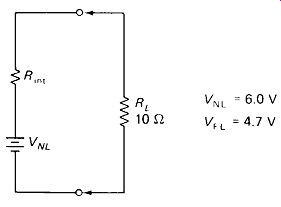
FIGURE 6-1 A battery should be tested under load (Example 6-1).
EXAMPLE 6-1 Figure 6-1 shows a battery-test setup. What voltage will this battery maintain with a load current of 150 mA?
Solution
First the internal resistance is calculated:
Now the drop at 150 mA is found:
= 5.6 V
The ampere-hour rating is simply the product of the current drain times the life until discharge of a battery. If the current drain is kept low enough so that the battery life is a few hours or more, the product of amperes times hours is relatively constant. However, for heavy currents and fast discharges (under an hour) the ampere-hour rating decreases progressively, down to half or less of its rated value.
Primary-Battery Comparison: The commercially most important primary batteries are the carbon-zinc, the alkaline, and the mercury types. The table and graph of Fig. 6-2 show comparisons of the three types.
The carbon-zinc is the so-called dry cell (although the chemical filler is actually a moist paste). Its chief advantage is low cost and commercial availability.
The alkaline battery is more expensive per cell, but it has a much higher ampere hour capacity than the carbon-zinc cell and therefore it may be more cost-effective.
It also has a lower internal resistance, making it more suitable for heavy-current loads. The mercury cell has an even higher capacity (and higher cost) and for many applications is the most cost-effective of the readily available primary cells. Its special advantages are long shelf life and relatively constant output voltage under light load.
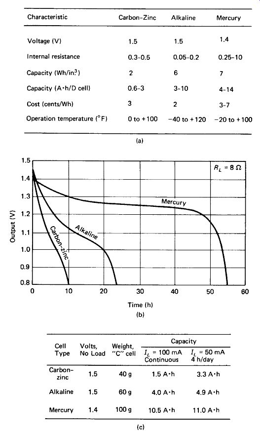
FIGURE 6-2 Comparison of three popular primary battery types: (a) general
characteristics; (b) continuous discharge curves for a C-size cell; (c) capacities
for a C cell under continuous and intermittent loads. Note the carbon-zinc
cell's improvement under intermittent load.
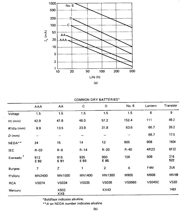
FIGURE 6-3 (a) Life of various size carbon-zinc cells as a function of continuous
load current, (b) Physical size and manufacturers' designations for popular
primary batteries.
Figure 6-3(a) shows the life that can be expected from various sizes of carbon-zinc cells at various load currents, and the accompanying table lists the physical sizes and manufacturers' numbers for the most common battery types.
Primary Battery Recharging: Recharging of carbon-zinc batteries is possible but should not be attempted on completely dead cells where the working voltage has dropped to less than 1.0 V per cell. Charging should be done over a 15-h period for 150% of the A - h capacity of the cell. A recharged carbon-zinc cell will have very poor shelf life and should be used immediately. Recharging should not be done more than twice.
6.2 SECONDARY BATTERIES
Lead-Acid Batteries: Lead-acid cells have long been used in automobiles and are still the most common choice where relatively large amounts of energy must be stored and re-chargeability is required. The nominal output voltage of this cell is 2.0 V. Figure 6-4 shows a typical fluctuation in terminal voltage as the cell is discharged and then recharged. Lead-acid cells can be recharged typically 500 times from the full-discharge state, although this number increases sharply if recharge is initiated after discharge of 50% or less. The A . h capacity of a lead-acid battery decreases for very fast discharge rates. The following schedule is typical:
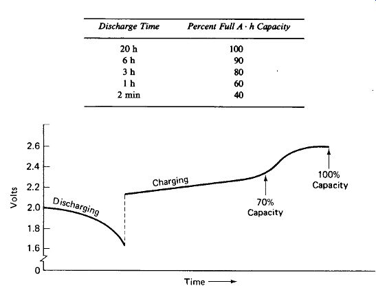
FIGURE 6-4 Typical discharge and recharge curve tor a lead-acid cell. Discharge
current is about twice charge current in this example.
As with most cells, the A - h capacity decreases at lower temperatures. For a lead-acid cell at 0°F the capacity of 60% of its value at 80° F.
Nickel-Cadmium Batteries: For lighter applications requiring recharge-ability, the nickel-cadmium (ni-cad) battery has become popular. Its energy capacity (1.5 W- h/in.^3 ) is considerably less than any of the primary cells but is still better than the lead-acid cell (1 W- h/in.3). The nominal output voltage of a ni-cad cell is 1.3 V. It displays a discharge-recharge curve similar to the lead-acid cell (Fig. 6-5).
The A - h capacity of a ni-cad cell is somewhat lessened for fast discharges. For example, the capacity for a 1/2-h discharge is typically 80% of that for a 4-h discharge. These cells are normally recharged over a 12 to 15-h period, but may be recharged at any rate that does not result in cell temperatures above 49° C (120°F).
Overcharging non-sealed cells will result in water loss from the electrolyte.
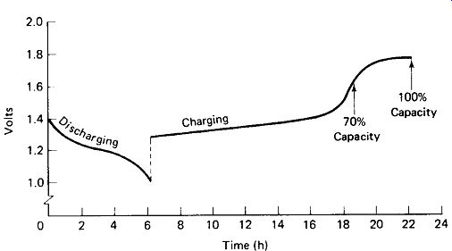
FIGURE 6-5 Discharge-recharge curve for a ni-cad cell. Charge current is
about one-half discharge current.
Secondary Cell Charging: The terminal voltage of a secondary cell fluctuates by 20 to 40% during charge, and it is desirable to employ a charger that supplies a relatively constant current in spite of this. The usual approach is to design a charger with a source voltage perhaps double the nominal cell voltage, and limit the current by means of a resistor. The total ampere-hour input required to recharge a secondary cell is typically 150% of its rated A h capacity. Trickle or maintenance chargers, delivering perhaps 5% of normal charging current, are often left connected to seldom-used devices (such as emergency lanterns) to assure full charge when needed. Ripple filters on ac-operated chargers are not absolutely essential, but adequate filtering will allow ripple-sensitive devices to operate directly from the charger and battery in parallel, which is often a convenience.
EXAMPLE 6-2
Design a charger for a 12-V, 60-A- h battery operating from the 60-Hz line. Charge time is to be 16 h. Include ripple filtering to 1 V p-p and a 5% trickle-charge function.
Solution
Figure 6-6 shows the charger. The current required is 1 = 6a h X 150% = 5.6 A 16 h
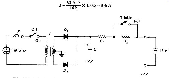
FIGURE 6-6 Battery charger with filtering and trickle charge (Example 6-2).
The voltage across C is chosen as 2K battery, or 24 V. The value and power dissipation of Rt are calculated:
Additional resistance to limit the charge to 5% is supplied by R 2:
The capacitor value can be calculated assuming a constant rate of discharge between the charging pulses, which are s or 8.3 ms apart.
This is about $30 worth of capacitor and should make the designer think seriously about some alternatives-electronic filtering or a pi-section choke filter perhaps.
The transformer must deliver a secondary voltage of 25 V peak on each side of the center tap to supply 24 V to charge the capacitor (the extra volt is for the drop across the silicon diode). Let us assume that the available transformers have a winding resistance (j secondary plus reflected primary) of 0.2 ohm. Using the techniques of Section 5.3 and Fig. 5-10, the no-load secondary voltage required is calculated:
Next, the secondary current requirement is determined:
The diodes should have a rather high surge current rating if it is decided to use the 46-mF filter, because the initial surge charging current on each half-cycle, when the supply is first turned on, will be limited only by the winding resistance:
1 surge R = 104 A each half
The time duration of this charging surge current is estimated as
r = RWC = 0.2 X 46 mF = 9.2 ms
6.3 PROPERTIES OF FUSES
A fuse is a low-melting-point conductor which is placed in series with a line and is designed to break the circuit by melting away when a specified current is exceeded.
The cartridge fuses generally used in electronics equipment are usually marked with three items of information as in the following examples:
The first set of characters refers to the manufacturers' case size and case material.
The A recalls that the cartridge fuse was originally designed for automotive applications; the G refers to a glass case and the B to a Bakelite, fiber, or ceramic case. The second number is the maximum continuous current in amperes that the fuse can handle without blowing. The third set of characters indicates the voltage that the fuse can safely withstand between its two ends without arcing after it has blown, in the face of a prospective short-circuit current of 10,000 A. In electronic equipment the prospective short-circuit currents are usually limited to a few amperes or less by transformers or house fuses, so it is common (and recommended by fuse manufacturers) to use 125-V-rated fuses to protect secondary circuits handling 500 V or more.
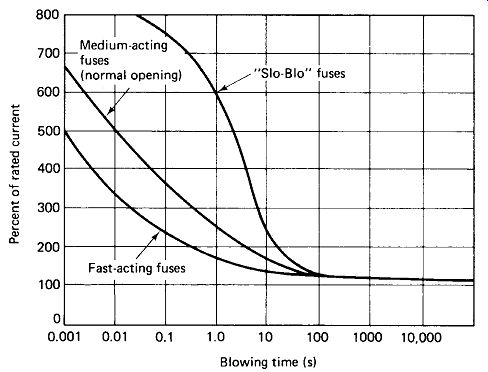
FIGURE 6-7 Typical response times of slow, normal, and fast-blowing fuses.
(Courtesy Littlefuse, Inc.)
Slow, Normal, and Fast Fuses: Cartridge fuses are available in normal, slow-blow, and fast-blow (instrument) types. Figure 6-7 shows how " slo-blo" fuses can withstand overloads up to five times their rating for a few seconds but blow on a 120% overload of extended duration. Slow-blow fuses can usually be recognized by their coiled internal construction. They are about twice as expensive as normal-acting fuses but are used extensively in electronic equipment because of the current surges which are encountered when the power is first turned on and the filter capacitors charge up.
Figure 6-8 shows the current inrush when a small solid-state lab oscilloscope is turned on. Notice that the peak surge current is about three times the steady-state current, which is not reached for about 12 cycles, or 0.2s. A normal-acting fuse can withstand a 300% overload for about 0.3s, but this is cutting it pretty close. A slow-blow fuse could withstand such an overload for about 6 s, and would be more likely to stand up to the abuses of high ambient temperatures and idiots who keep flicking the power on and off.
Vertical: 1 A/div
Horizontal: 2 cycles/div
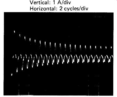
FIGURE 6-8 Line-current inrush due to filter-capacitor charging when an
instrument is first turned on.
Fast-acting fuses which blow in as little as 1 ms under a 500% overload are available (at somewhat higher cost) for the protection of meter movements, solid-state diodes, and other semiconductors which can be destroyed in a few milliseconds by overcurrents. Notice from Fig. 6-7 that even these require nearly 0.5 s to react to a 200% overload. For the ultimate in fast overcurrent protection, all-electronic (no-moving-part) circuit breakers can be designed to trip in a few microseconds for even a 110% overload.
Fuse Selection: Manufacturers generally recommend that a fuse be operated at no more than 75% of its rated current to avoid unnecessary shutdowns. Ambient temperature should also be considered when selecting fuse ratings. Figure 6-9 gives one manufacturer's recommendations.
Remember that fuse ratings are in amperes rms, not amperes average. For an instrument whose entire current drain is a highly filtered rectifier circuit, it is quite likely that the true rms line current will be two or three times the value indicated on an average-reading ammeter. The article on pulsed load currents in Section 5.3 explains this in detail. See, in particular, Fig. 5-10(b).
Curve A : Slo-Blo fuses Curve B: Medium-and fast-acting fuses
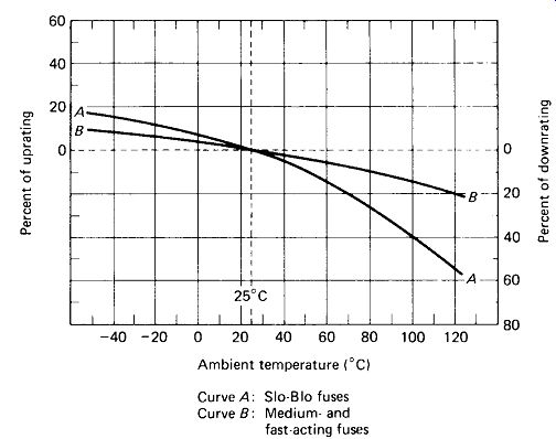
FIGURE 6-9 Effect of ambient temperature on required fuse ratings. (Courtesy
Littlefuse, Inc.)
Fuse Resistance: The resistance of a fuse element generally causes a voltage drop of a tenth to several tenths of a volt at full current, and the fuse case may become noticeably warm, especially with high-current fuses. Slow-blow fuses generally have slightly higher resistances than do quick-blowing types. Some typical resistances for electronic fuses are as follows:
A fast ... 4.3 ohm ± A fast ...
3.2 1 A fast ... 0.2 ohm 1 A slow ... 0.3 ohm 2 3 A slow ... 0.1
These resistances remain quite constant from very low to maximum current.
Indicating Fuses: Fuses are available with a spring-loaded pin which protrudes from one end of the case upon separation of the fuse element to provide a visible indication of fuse failure. A low-current lamp rated for the supply voltage can be connected across a fuse to provide a similar function. (An NE-2 lamp in series with a 100-k ohm, j-W, resistor is fine for 110-V lines.) Such indicators are valuable where several fuses are located together and identification of the failed device might otherwise be difficult.
6.4 CIRCUIT BREAKERS
Thermal-Type Breakers: Circuit breakers perform the same basic function as fuses, but they can be reset rather than replaced after they are tripped by an overcurrent. There are two basic types: thermal and electromagnetic. In the thermal types, excessive current heats a bimetallic strip, which bends, releasing a trip lever and opening the contacts. Thermal breakers are at a disadvantage in environments where temperature is not controlled because their trip point varies with ambient temperature. Figure 6-10(a) shows trip time versus current for a typical thermal breaker. Figure 6-10(b) shows a similar curve for a fast-acting " heater wire" type of thermal breaker. Note that a 500% overload may still require 0.2 s to tip this relatively fast thermal breaker.
TIME vs. CURRENT TIME IN SECONDS (b)
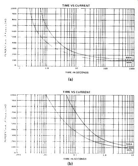
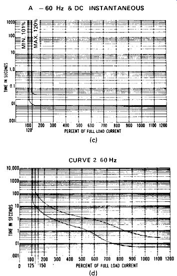
FIGURE 6-10 Thermally operated circuit breakers (a) have a response time
similar to slow-blow fuses. Hot-wire type breakers respond about as fast
as quick-blow fuses (b). Magnetic breakers (c) are very fast.
Magnetic-hydraulic breakers (d) are slow for moderate overloads but very fast
for extreme overloads. (Courtesy Potter & Brumfield division of AMF Corp.)
Magnetic and Hydraulic Breakers: Magnetic circuit breakers utilize the magnetic field created by overcurrent in a coil of wire to attract an armature which trips the release mechanism. As shown in Fig. 6-10(c), such a breaker can respond in about 10 ms. Magnetic-hydraulic breakers have two trip mechanisms. The first is identical to the armature described above but is designed to trip only on extreme overloads of about 800%. The second is activated by a piston which is pulled slowly through a cylinder of hydraulic fluid by lesser overloads. Figure 6-10(d) shows the time versus current curve for a magnetic-hydraulic breaker. Such a curve is ideal for many applications because a 200% load (such as might be encountered in the normal starting of a motor) can be tolerated for a few seconds, but a really catastrophic overload (such as a short circuit) will blow the breaker in a few milliseconds.
6.5 PROPERTIES OF SWITCHES AND RELAYS
In selecting switches and relays, the following considerations should be made, in addition to the number of poles and positions required:
1. Current and voltage rating of the contacts
2. Shorting or non-shorting contacts
3. Contact bounce
4. Actuate time
5. Life span
Current and Voltage Ratings: Relay and switch contacts are generally rated for resistive loads at dc or 60-Hz ac. When switching inductive loads (transformers, magnet coils, motors, etc.), the contacts should be operated very conservatively (i.e., 2-A or 5-A contacts to carry 1 A to an inductive load). This is because the inductor will produce a large kickback voltage when the switch opens, thereby causing arcing and subsequent pitting of the contacts. A suppressor circuit can, be wired across the switch to minimize this problem, as depicted in Fig. 6-11(a). In the formula for C, r is the time required for the contacts to open sufficiently to prevent arcing. This may be estimated as 1 ms for small relays and toggle switches and 10 ms for heavy power contacts. If the source is ac, C may have to be lowered considerably to raise its reactance to the point where current leakage through it is no long! r objectionable.
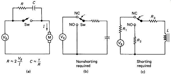
FIGURE 6-11 (a) An RC snubber reduces switch arcing from inductive kick
back. (b) In some circuits a make-before-break switch would short the supply
or a capacitor during transition, (c) In other circuits a break-before-make
switch would interrupt an inductor current.
Shorting versus Non-shorting: Most toggle switches and relays have non-shorting contacts. This means that the armature (common) pole leaves the normally closed pole before it touches the normally open pole, and vice versa. This is also called break-before-make or form C contacts. However, there are switches (especially rotary switches) whose contacts make-before-break, and these are called shorting switches or form D contacts. Often the difference between the two is not important, but Fig. 6-11(b) and (c) indicate how it can be critical.
In Fig. 6-11(b), if the NC (normally closed) and NO (normally open) poles are shorted for even an instant during switching, the source will be shorted, with catastrophic results. In Fig. 6-11(c), if the C pole is left floating for an instant during its transition from NC to NO, the inductor current will be interrupted and the resulting kickback voltage will arc the switch, resulting in pitted contacts.
Contact Bounce and Actuate Time: Switches and relays do not actuate instantly, nor do they always make contact with a single clean motion. The following table indicates the behavior that can be expected from various types of contactors.
Switch Type Actuate Time (ms) Bounce?
Toggle switch
Rotary switch
Coil and armature relay
Reed relay
Figure 6-12 shows scope traces of contact bounce for a toggle switch and a coil-and-armature relay. Top trace: switch output Bottom trace: relay output Vertical: 10 V/div each trace Horizontal: 1ms/div
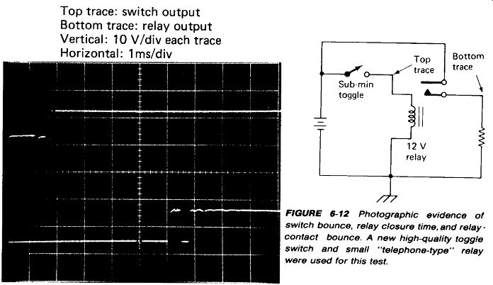
FIGURE 6-12 Photographic evidence of switch bounce, relay closure time,
and relay - contact bounce. A new high-quality toggle switch and small "telephone-type" relay
were used for this test.
Life Expectancy: Good-quality rotary and toggle switches generally guarantee a life of 50,000 to 100,000 mechanical cycles. Inexpensive switches have a life span much shorter than this. Such limitations cannot be ignored when designing equipment for industrial or military use. Consider the case of a rotary switch in a piece of test equipment on a factory assembly line which is operated once every minute, 8 h/day, 5 days/week, for 1 year. The total is 124,800 operations! The cost in downtime and engineering time when that switch fails could easily exceed $1000.
The false economy of using a $5 switch instead of a $35 switch in such an application is quite obvious.
6.6 PROPERTIES OF LAMPS
Incandescent Lamps produce light by using an electric current to heat a tungsten filament to a temperature in the vicinity of 2000 K. The great majority of energy produced, however, is not visible light but infrared (radiant heat), as documented in Fig. 6-13(a). Typical efficiencies (visible light energy/electrical input energy) for various types of light sources are as follows:
Neon glow < 1% Incandescent 1.5-3% Mercury ss6% Fluorescent 7-12% High-pressure sodium 16-22% Typical energy distribution of some of the more popular subminiature incandescent lamps
Electrical Characteristics Energy Emission Characteristics (%)
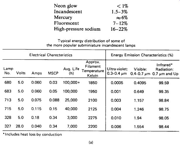
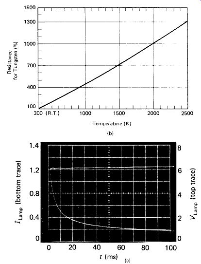
FIGURE 6-13 (a) A very small percentage of an incandescent lamp's energy
appears as visible light. ,Includes heat loss by conduction (b) Resistance
of a tungsten filament increases by about X10 from cold to hot filament. (Courtesy
Chicago Miniature Lamp Works.) (c) Current inrush for a No. 47 pilot lamp on
a 6.3-V dc source.
Inrush Current: A tungsten filament at 2000 K has a resistance that is about 10 times its room-temperature resistance, as shown in Fig. 6-13(b). It follows that the current surge when a cold lamp is first turned on will be nearly 10 times the final operating current. This inrush phenomenon [illustrated in Fig. 6-13(c)] has implications for lamp life and circuit fusing. If a system can be devised to turn the lamp on slowly, the thermal shock due to inrush current will be reduced and life will be increased. Also, if inrush can be avoided, fast-acting low-threshold circuit breakers can be employed for more complete circuit protection.
Flashover at Burnout: Incandescent lamps usually fail from thermally induced stress just after the power is switched on. Everyone has witnessed the brilliant flash of light which an incandescent lamp makes when the filament parts. This is due to ionization of residual gases, which starts at the point of rupture and spreads to the space between the filament supports. Ionization current in 50- to 150-W 120-V lamps commonly reaches 100 to 200 A and lasts from 1 to 5 ms.
This flashover current can trip a circuit breaker or fuse, causing unnecessary shutdown when one lamp of a parallel group fails. In lamp circuits containing diode, SCR, or triac series pass elements, flashover current can destroy the semiconductor.
A small resistance in series with the lamp is the simplest way of limiting flashover current. For example, 10 ohm in series with a 60-W 120-V lamp will dissipate only 2.5 W and drop the line voltage by only 5 V, yet it will limit flashover current to 12 A, which should be within the surge-current rating of a 1-A semiconductor. As shown under lamp rerating below, this will result in a 14% decrease in light output and a 67% increase in lamp life.
Lamp Deterioration: Several modes of deterioration are evident in most in candescent lamps. Filament movement is common in coil-filament lamps and is caused by relaxation of stresses in the filament and its mounting with time and temperature. The result may be a current increase on the order of 10% and a brightness increase on the order of 20% after 1000 h.
Filament evaporation thins down the filament wire, increasing its resistance.
The result can be a 10% current reduction and a 35% brightness reduction after 1000 h. The products of a filament evaporation can be deposited on the inner glass surface, causing lamp darkening, which may reduce lamp brightness by several percent.
Lamp Rerating: Manufacturers' specifications for incandescent lamp light output (mean spherical candlepower; MSCP), rated life, and filament current are all given for some arbitrarily selected filament voltage. If it is necessary to increase lamp life by a factor of 3, this can be done simply by reducing the lamp voltage by a certain amount. Of course, the output (MSCP) and current drain will be reduced by this change. Three formulas for rerating incandescent lamps at other than specified voltages are:
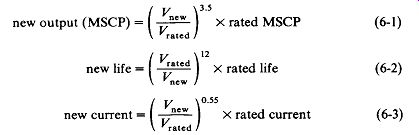
(6-1)
(6-2)
(6-3)
EXAMPLE 6-3
A type-327 lamp [see Fig. 6-13(a)] is to be operated at 24 V rather than 28 V. What will be its new output, life, and current?
Solution new MSCP = ( |) X 0.34 = 0.20 ( 28 \'2
j x 7000 = 44,000 H
/ 24 \0-'' new current = I 1 X 0.040 = 0.037 A
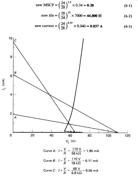
FIGURE 6-14 Characteristics for an NE-2 neon lamp with several load lines.
Line C will not ignite the lamp but will hold it in conduction once it is turned on.
Notice that a small change in lamp voltage (-14%) causes a severe drop in output ( - 41%) but a dramatic improvement in lamp life (X6.3).
Gas Discharge Lamps: Certain gases can have one of the outer electrons ripped loose from their atoms by the application of a moderate voltage. The neon glow lamp makes use of this ionization phenomenon. Note from Fig. 6-14 that no current at all flows in this lamp until the firing voltage is reached, whereupon an excessively large current would flow if not limited by an external resistor. Once ignited, the lamp operates at a voltage typically 25 to 50% below the firing voltage.
The voltage in the operating range is relatively constant with current change, leading to the occasional use of neon lamps as voltage regulators and peak-voltage limiters. Neon glow lamps are available with nominal firing voltages from 65 to 150 V, although actual voltages may vary by ±25% from unit to unit and by several volts with age and temperature for the same unit. The life span for neon lamps is not unlimited, being typically in the range of 25,000 h at full rated current. Figure 6-15 gives the characteristics of the more popular neon and incandescent lamps used for electronic applications.
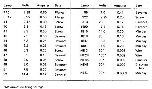
FIGURE 6-15 Characteristics of popular lamps used in electronic devices.