
By J. A. "Sam" Wilson, CET
Your comments or questions are welcome. Please give us permission to quote from your letters. Write to Sam at:
J. A. "Sam" Wilson c/o Electronic Servicing
P.O. Box 12901 Overland Park, Kansas 66212
Applied Magnetics
A discussion of magnetics was started in a previous Technical Notebook, and it will be continued.
My goal is to review the basics of magnetics first, and then to show how these basics lead to a better understanding of magnetic and electromagnetic devices.
This month, the center of discussion is measurements.
Don't compare electricity and magnetism
A comparison of the similarities between magnetism and electricity has been done many times to help students understand magnetism.
However, such comparisons often are more confusing than helpful.
And wrong ideas are difficult to change, once they are learned thoroughly.
Therefore, I recommend only a listing of differences, not similarities, as shown in Table 1. (This table was included on page 52 of the April issue, but one section was garbled.)
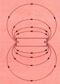
Figure 1. Magnetic flux lines

Figure 2. Magnetic induction
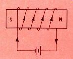
Figure 3. Electromagnetic induction.
The magnetic field
A magnetic field consists of flux lines, which are nothing more than regions of equal magnetic intensity around a magnet.
A favorite school experiment is to place a piece of paper over a magnet and sprinkle iron filings on the paper. The filings concentrate over the magnet in curves showing the locations of the flux lines, as shown in Figure 1.
Unfortunately, a wrong impression often is given by the arrows that are usually placed on the flux lines. The arrows really show the direction that a north pole would move, if it were placed in the field.
(The arrows do NOT show any movement of the flux lines. The flux lines are steady, and do not move.)
Obtaining magnetomotive force:
To produce flux lines in a material, such as a piece of soft iron, a source of magnetic flux is needed. This is called magnetomotive force (MMF), and it causes flux lines to exist in a material.
Magnetomotive force can be obtained by two methods: by magnetic induction; and/or by electro magnetic induction.
The principle of magnetic induction is shown in Figure 2, where a permanent magnet serves as the source of flux lines. When the magnet is placed near the soft iron, flux lines are induced in the iron.
Figure 3 shows a second way of obtaining a magnetomotive force. A coil is placed over a soft-iron core, and current is forced through the coil. The coil's electromagnetic field serves as the source of MMF, and the method is called "electromagnetic induction."
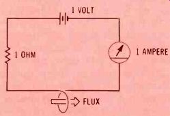
Figure 4 One ampere-turn of MMF
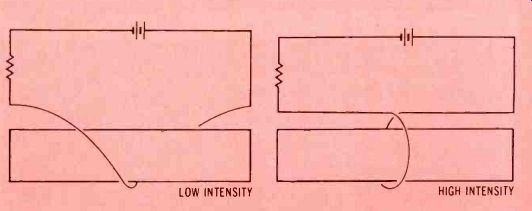
Figure 5 Turn spacing changes the intensity
--------------------
Table 1
Differences Between Magnetic And Electronic Systems
Magnetic flux often is compared with current in an electric circuit, BUT...
...current flows through a circuit, while magnetic flux does not move through a magnetic circuit. Further, current is con fined to the conducting path, but some flux can "leak" from a magnetic circuit.
Magnetomotive force (MMF) of ten is compared with electro motive force (EMF), BUT...
...neither MMF nor EMF is a force. Both are units of work.
Reluctance often is compared with resistance, BUT...
...resistance often is linear in electric circuits, while reluctance almost never is linear.
Current always has an accompanying magnetic field, BUT...
...a magnetic field is not always accompanied by an electric cur rent.
Current through a wire produces heat, BUT...
...flux through an iron core does not produce heat.
--------------------
Measuring MMF
After we have defined MMF as the source of flux, we need a way of measuring it.
One method is to use a standard magnet (one that is manufactured to certain rigid specifications). In a laboratory setup, an unknown source of MMF can be compared with the MMF of the standard magnet.
Although the method of measurement by using a standard magnet can be very accurate, there are problems. Such magnets are expensive, and the procedure is complicated, as well as requiring mathematical computations.
An easier procedure is to produce a known MMF by current in a coil, as illustrated in Figure 4. Measurements of voltage, current, and resistance are easy, so this method is cheaper and more convenient than the one using a standard magnet.
Magnetic intensity
Although it is true that MMF sets up the flux in a material, it's NOT a useful parameter when taken by itself (see Figure 5). If the turn of wire is spaced closely, then all of the MMF ampere-turn is concentrated in a small region. If the same one turn is stretched out, the MMF is stretched over a larger area.
Therefore, a magnetomotive force (MMF) can be concentrated in a short length, or it can be stretched over a longer distance. That's why the ampere-turn-per-unit-of-length is used as a unit of magnetic intensity (rather than ampere-turns alone). In formulas, magnetic intensity is represented by a capital letter "B."
Field strength
The amount of flux is one indication of the magnetic field strength. Obviously, more flux lines produce a stronger field. But, again there is a problem of how the flux lines are distributed.
Four flux lines spread over a large area, as shown in Figure 6, would not produce as much magnetic field strength as if those same four flux lines were concentrated within a smaller area.
Therefore, when we describe magnetic field strength, it isn't enough to specify how many flux lines there are. Instead, the number of flux lines per unit area must be stated. This is called the magnetic flux density, and it is represented by a capital letter "H."
The B-H curve
The characteristic curve of a magnetic material is a hysteresis curve. In Figure 7, compare the characteristic curves of a silicon diode and a piece of soft iron.
The horizontal axis of the diode curve represents the applied voltage, which can be thought of as the moving force for the electrons.
With the curve for soft iron, the horizontal axis represents magnetic intensity, which can be viewed as the force that establishes the flux.
With the diode curve, the vertical axis represents current-the result of applying a voltage. The vertical axis of the hysteresis curve is flux--the result of applying a magnetic force.
Both curves are non-linear, so Ohm's Law won't work with either situation. In addition, the magnetic curve shows hysteresis (different curves for increasing or decreasing magnetic intensity).
Next month, I'll finish the discussion about magnetic measurements, to be followed by applications of magnetism and electro magnetism.
Figure 6--Flux per area determines density.
Figure 7--Comparison of characteristic curves.
------------
(adapted from: Electronic Servicing magazine, Jun. 1978)
Next: Jul. 1978
Prev: Link |
Also see: