
Charged Versus Uncharged Capacitors
By J. A. "Sam" Wilson, CET.
Your comments or questions are welcome. Please give us permission to quote from your letters. Write to Sam at:
J. A. "Sam" Wilson c/o Electronic Servicing P.O. Box 12901, Overland Park, Kansas 66212
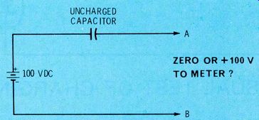
Figure 1. What is the voltage between terminals A and B? This is the question
that has aroused some controversy.
Capacitor Question Revisited
One of the readers who disagreed with some of the things I wrote recently about capacitors is Larry Reid, who lives in California.
Specifically, he objected to my answer for question 3 of the quiz in the February 1978 issue of Electronic Servicing.
The circuit is printed again in Figure 1. My answer under the stated conditions was and is: 100 VDC is present at the output. An electrostatic meter (which draws no current from the circuit) will show a steady 100 volts. However, capacitances in real-life circuits don't remain uncharged very long. That's where Reid went wrong. Just as soon as current (even from the load of a VTVM) is drawn from the output, the capacitor begins to accept a charge, and the output voltage drops. The time constant of the circuit determines how fast the DC voltage drops. And, notice that the conditions of Figure 1 have changed now, because the capacitor no longer is totally uncharged.
To prove his contention that uncharged capacitors don't pass DC voltage, Reid sent me a 1.5-volt battery wired in series with a 220-picofarad capacitor (Figure 2).
He said the capacitance was reduced to compensate for the lower voltage, and that his VTVM measured zero voltage at the output.
------------
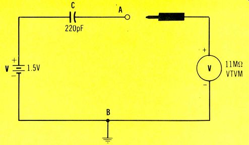
Figure 2. One doubting reader sent in this battery and capacitor, saying
he couldn't measure any DC voltage with his VTVM. A larger capacitor would
have provided a DC voltage pulse of sufficient duration to be read on his
meter.
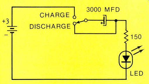
Figure 3. Visual proof of the capacitor DC charging current can be made using
the schematic shown here. LEDs operate mainly from current and have almost
instantaneous response.
---------------
Actually, the capacitance value has nothing to do with the principle, but a larger capacitor value would have given a short pulse of DC voltage, thus showing him the transient nature of the action.
Mathematical proof:
The time constant of any resistance-capacitance circuit can be calculated easily from the formula:
Time equals the resistance (in ohms) multiplied by the capacitance (in farads). Assuming that a VTVM having an input resistance of 11 megohms was used, the time constant is: T = 11 X 10^6 X 220 X 10^-12 T = 0.00242 seconds
That's the time required for the charge in the 220 pF capacitor to reach 63.2% of the supply voltage.
Any voltage across the capacitor must be subtracted from the supply voltage to give the output voltage.
So, at turn-on, the capacitor has zero voltage across it, leaving the full 1.5 supply volts at the output.
After one time constant of 0.00242 seconds, the capacitor has 0.948 volts, and the output voltage is 0.552 volts.
After two time constants totaling 0.00484 seconds, the capacitor has 0.599 volts and the output is 0.349 volts.
A capacitor is considered to be fully charged after 5 time constants.
In other words, after about 12 milliseconds (0.0121 second), the capacitor charge is 1.5 volts, and the output measures zero volts.
A VTVM DC voltmeter will show zero volts across the output of Figure 2, because the short pulse of voltage decays to zero volts before the pointer can move up from the resting position. A DC scope, or other fast voltmeter, can show the short pulse, but your eyes will have difficulty following it.
Of course, the capacitor charging can be slowed by increasing the Figure 2 capacitor value, allowing a VTVM or FET meter to follow the changing output voltage.
For example, I first tried a 150 microfarad electrolytic, but stopped the count after several minutes, when the output voltage remained above 1.5 volts. Another capacitor (marked 10 microfarads) required about 80 seconds before the VTVM reading dropped to the 1-time-constant voltage of about +0.95 volts on the 1.5-volt range. Also, a 0.1 capacitor dropped to the same voltage in about 1 second. (Digital meters are not suitable for tracking these large voltage changes.) Or, you can do an interesting (but uncalibrated) visual experiment using an LED as the indicator, since it has instantaneous response.
Wire the circuit of Figure 3, which includes a convenient way of discharging the capacitor. The LED flash, when it's switched to charge position, begins with full intensity and rapidly dims over a period of two to three seconds (depending on the individual components). The capacitance must be very large, because the LED has a low resistance.
Q. Passes current when charged?
Reid also wrote, "In your explanation of why we should read (the battery voltage) between points A and B, you state that a capacitor passes current until it becomes charged. Not so.... no current can pass until the capacitor becomes charged." Probably the preceding information has convinced Reid already. In addition, I could refer him to the textbook charge and discharge curves of voltage and current with capacitors. Instead, let's consider the schematic of Figure 4. If the capacitor actually is charged al ready (as Reid evidently believes), its voltage MUST equal the battery voltage, but have the opposite polarity. Therefore, the voltages will cancel, leaving zero volts between points A and B. So, if a resistor is connected from A to B, no current can flow.
As we found from the information and experiments just given, capacitor current DOES flow strongest when the capacitor is uncharged, and it diminishes ac cording to the time constant. Perhaps I should explain that a VTVM connected between A and B of Figure 2 actually is reading the capacitor current by measuring the voltage drop across the internal resistance of the VTVM. Please study the schematic.
Thanks Mr. Reid, thanks very much for the questions and taking time to write.
Incidentally, a number of technicians objected to the previous quote because I said the "current flows through the capacitor." Their point is well taken, if you define current as being a flow of electrons. However, I don't define current that way, so my model is not in jeopardy.
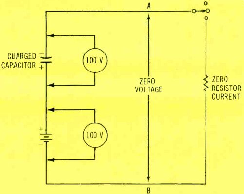
Figure 4 In answer to another dissenting opinion, it's true a charged capacitor
has full supply voltage across it. Therefore, a charged capacitor in Figure
1 or Figure 2 would give this equivalent circuit, which would not ever allow
any output current or voltage. Perhaps the reader was confused by voltage
and current that can be drawn (discharged) from the two leads of a capacitor
after it has been charged.
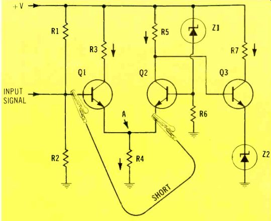
Figure 5. What actions occur when the base of Q1 is shorted to the emitter
of Q2? Arrows show "conventional" flow of current.

Figure 6. Aristotle's "Golden Mean" applies to technicians, who
also operate most efficiently when they have equal amounts of theory and
practice. Where do you rate yourself?
Question About a Practice Question
Allen Daubendiek of Beatrice, Nebraska, sent in a query about a question in one of my CET Practice Tests. The question is repeated here.
Question: In the circuit of Figure 5, which of the following would most likely occur when the base of Q1 is shorted to the emitter of Q2?
(1) Transistor Q2 would be destroyed. (2) Very heavy collector current would flow in Q3. (3) The collector of Q2 would become less positive. (4) Transistor Q1 would be cut off.
The answer in the Practice Test is given as (2). That answer is wrong! The correct answer is (4).
Mr. Daubendiek correctly reasoned the following circuit action:
Since the emitter of Q1 is connected to the emitter of Q2, shorting the base of Q1 to the emitter of Q2 is the same as shorting the base of Q1 to its own emitter-the forward bias is eliminated, along with the Q1 C/E current.
This reduces the current in resistor R, thus decreasing the emitter voltage.
Reduced Q2 emitter voltage increases the forward bias, the same as a more-positive base. Therefore, Q2 conducts more C/E current.
Increased conduction by Q2 reduces its collector voltage, and with it the Q3 base voltage of Q3.
Less positive voltage at the base of Q3 decreases the Q3 C/E current.
Daubendiek has an excellent grasp of bipolar-transistor theory.
There is an important point to be made here. Mistakes sometimes creep into printed material, even after the many times it is proofread.
Therefore, if you don't agree with some fact (and you have not overlooked an important point), then please write to me about it! I'll be glad to exchange information with you. But there's one exception. I don't respond to sarcastic or insulting letters. Your letters have been very professional, and I thank you.
Where's The Resistance
A pleasant letter from Robert Saunders, electronics instructor at the James Whitcomb Riley High School in South Bend, Indiana, says in part, "You refer quite often to the resistance of a capacitor or inductor." He goes on to say that the internal opposition to current flow is called reactance.
Of course, Saunders is correct. However, in a quick search of the articles, I couldn't find any such reference. I would appreciate you telling me the issue and page number of any examples.
Practical components have DC resistances, such as the leakages in capacitors. Could that have been the way the word was used? Editor's Note: In my past hobby of designing elaborate audio amplifiers, I made extensive use of a capacitor's equivalent resistance. Of course, a capacitor's equivalent resistance to AC is the "capacitive reactance," but it is measured or stated in ohms versus frequency.
Perhaps during the editing, I regressed to this short cut. In any event, please show us some examples, and we will make corrections if the wrong term was used.
The "Golden Mean" You will remember from your study of Greek history and mythology that Aristotle was obsessed with the idea of finding the greatest "virtue." His approach to the greatest virtue was called the "Golden Mean," which is always halfway between extremes.
Practical applications
By considering theory and applications as opposite ends of the extreme, Aristotle probably would say that a good (virtuous) technician practices the Golden Mean.
As shown in Figure 6, equal portions of theory and practice are required to achieve a balance.
Aristotle's philosophy certainly has much to recommend it. A man who has knowledge of nothing but theory, without any practical applications, tends to be useless, according to his value to employer and customers.

Figure 7. Another reader offers his theory explaining the multiple poles
measured in a magnetized welding rod.
Once, long ago, I knew a genius in electronics who was stumped by a vacuum-tube voltmeter (VTVM) which would not measure resistance.
This brain had disassembled the VTVM in a vain effort to find the trouble. He spent two whole days analyzing the circuit, but failed to find any bad parts. However, someone else had cannibalized the unit by taking out the ohmmeter battery! This theory man was so obsessed with the problem that he actually redesigned the VTVM so it worked better, but he never could make the ohmmeter function operate.
At the other extreme is a person who has all practical-application experience and knowledge, but doesn't know any theory. Such a person also is worthless. I have known of anti-theory technicians (?) who butchered new circuits in disastrous attempts at repairing them. Their practical experience did not (and could not) prepare them for repairs of any new receivers.
I once saw a technician installing an antenna in Akron, Ohio. He formerly had worked for a friend of mine, so I knew him slightly. As we talked, I told him about a class I was teaching. "I don't go for all that theory stuff," he said. "The class wouldn't help me." I watched in amazement as he worked. He laid the twin-lead wire (coming from the VHF antenna) flat against the roof, taped it along several feet of drain pipe, and finally brought it through a window. My knowledge of trans mission lines told me that the moisture on the line from rain or snow would give a poor picture.
Sure enough, within three weeks another team arrived to rework the installation, particularly the location and securing of the twin-lead.
Apparently, this made the customer satisfied with the picture, because no other work was done on the antenna for several years.
Unfortunately, the anti-theory guy probably didn't get any feed back report to tell him of his mistake.
Tests
When I wrote the CET tests, I constantly was faced with this problem of the Golden Mean between theory and practice. The association officials and I felt each technician should know both before he could be certified. Although I arranged the tests very closely for half theory and half practical experience, the first versions of the tests were criticized for being oriented to theory.
To prove or disprove thecom plaints, we gave the same tests to some college professors, and compared their grades with those of an equal number of practicing electronic technicians. The technicians made higher scores on the tests, indicating that the professors, who undoubtedly were much stronger in theory, could not answer the practical questions.
Of course, the test will please only those who have equal strengths in both theory and practice. All others will think the tests are unbalanced.
Look again at Figure 6, and mark an arrow on the drawing where you would rate yourself at this time. Then, consider whether you should take action to increase either your practical or theoretical knowledge to bring you nearer the "Golden Mean."
Letters Delayed In Moving
If you sent me a letter, but have not received an answer, please forgive me. I have been moving, and my packing was done by a young man who works for me part time. I made the mistake of telling him to pack everything in boxes, and then left for several hours.
When I came back, he was just folding my model of the Hindenburg, and placing it in the last box.
All of my correspondence is some where in those boxes.
So, if you haven't received an answer, please write again. That will be quicker than waiting until the many boxes are unpacked.
Magnetic Pole Mystery
In the March issue of Electronic Servicing, I described the unsuccessful attempts of my students to magnetize a 3-foot length of steel welding rod so there is a north pole at one end, a south pole at the other end, but no extra poles in between. When they used acom pass to check the results, there were many NN and SS poles in between, as shown in Figure 7.
In a letter, Edward Marceau Jr., gave his reply. The pertinent parts are quoted here.
"The answer is basically simple. As you probably learned long ago in physics class, a steel bar is made up of an endless array of individual magnets (molecules) that are lined up north and south. Also, if you have ever done the experiment with iron filings sprinkled on a piece of paper, and a magnet held underneath, then you know that there are magnetic lines present.
"Now, back to the welding rod. (Why this type instead of iron?) The rod does have continuous field lines from end to end, but because of the weak magnetic field present, and the low sensitivity of your compass, you cannot detect the outer field lines. Instead, you are seeing the inner field lines which have + and - nodes just like standing waves in an antenna.
"What is needed is a Hall-Effect Magnetometer. It's a sensitive device for detecting magnetic fields, and one can be built from plans in the 1977 issue of Popular Electronics Experimenters Handbook, pages 48-51."
Dear Mr. Marceau: I want to thank you for taking the time to write. You must have spent appreciable time thinking about the problem.
At this time, I'm not going to agree or disagree with what you say. Perhaps other readers will want to comment. Let's hope so. I'll discuss the subject again in a later issue.
------------
(adapted from: Electronic Servicing magazine, Sept. 1978)
Next: Oct. 1978
Prev: Link |