
By J. A. "Sam" Wilson, CET.
More Magnetic Memory
In a previous article, I showed how coils could be wound around ferrite cores, and the device used as a magnetic memory. This information is an extension of the same principle.
Any motion of electrons through a conductor ALWAYS produces a magnetic field at right angles to the conductor. No exceptions ever have been found for the rule. Even in cases where the electron flow is not confined to a conductor (such as an electron stream in a cathode-ray tube), there is an accompanying magnetic field.
The direction of any magnetic field is defined as the direction that a "unit" north pole would move, if placed in that field. Of course, a unit north pole is an imaginary north magnetic pole without an accompanying south magnetic pole.
Left-hand rule
Direction of the magnetic field around an electron current flow can be determined by the "left-hand" rule. Imagine that you are grasping the wire with your left hand (see Figure 1), with your thumb pointing in the direction of electron flow.
Then, your fingers are pointing in the direction of the magnetic field.
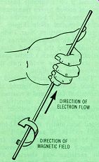
--------- Figure 1. The "left-hand" rule shows the direction
of magnetic field produced by this direction of electron current flow. ELECTRON
FLOW VERSUS THE RESULTING MAGNETIC FIELD.
Magnetizing a core
Figure 2 shows electron current flowing in a single wire that passes through the center of a ferrite core.
If the electron current has enough amperage, the core will become magnetized, and the flux will be in the direction shown by the arrows on the core. This flux remains, even after the current flow stops.
By definition, if the core has a magnetic flux, a logic 1 level has been memorized. On the other hand, the lack of any magnetic flux indicates a logic 0 level. Those are the only two conditions permitted with this simple system.
In Figure 3, a second wire is threaded through the core. It will be used to determine the logic state of the flux.
Reading the flux
Suppose the core flux of Figure 3 has been established previously by an electron current pulse flowing from A to B. A second pulse, also from A to B, will not change or affect the flux stored in the core, but an equal pulse from B to A will eliminate the core flux. When the flux is cancelled, the resulting change of flux will induce a voltage in the wire between C and D.
Now, notice that inducing a voltage in a wire doesn't necessarily mean that current MUST flow. If wire C -D is part of a closed circuit (that is, has continuity external to the wire), current will flow. If an open circuit is across the C -D wire, no current will flow. These simple facts are important for understanding how only one core can be operated in a memory system having many thousands of cores. This will be explained later.

Figure 2. Electron current in a wire through a ferrite core produces a flux
in the core of the same direction as the previous "left-hand" rule.
Sufficient current magnetizes the core. ELECTRON CURRENT MAGNETIZES THE CORE.

Figure 3 Addition of a second wire through the core provides a method of
determining if the core originally was in the logic 1 or the logic 0 condition.
C-D SENSE WIRE DETERMINES IF A 1 OR 0 HAS BEEN MEMORIZED.
Refreshing the state
The simple memory described in a previous article had three conventional coils on one core. The first two coils performed the same functions as wires A-B and C-D in Figure 3. A third coil was added to re-establish the core flux, when it was eliminated by the sensing current.
In the same way, a third wire is added to the core, as shown in Figure 4. Wire E -F is used to refresh the memory. In other words, it re-establishes the original flux.
I'm not finished with my discussion of applied magnetics. The principles of magnetic memory will be extended in a future issue.
Welding Problem
In a recent letter, Mr. Earl Swallow writes, "Some years ago, I bought a Craftsman AC welder (40 amps to 230 amps), but never was happy with it. With 3/32-inch #6013 30-80 ampere rod and #308 stainless 60-90 amp, it took a long time to strike an arc, and I had a lot of trouble holding it. Using a higher amperage might burn holes in the material.
"Recently, I bought a 100-volt 250-ampere stud rectifier, and mounted it on a suitable heatsink that was cooled by the transformer fan. I connected it between the taps and the ground cable (Figure 5), trying both polarities. Next, I wired an electrolytic capacitor across the rod holder and the ground clamp.
The capacitor gave it a better spark for starting the weld, but the improvement was slight.
"Then, the capacitor exploded in a cloud of smoke. I figured the rectifier had failed, and a resistance test proved it was shorted. I decided to try welding without the capacitor, and to my surprise, it welded beautifully! With 3/32–inch #6013 rod at 40 amperes, I was able to strike an arc easily and produce a nice bead. I was amazed! The rectifier was shorted, the capacitor was open, but it welded great. According to my voltmeter, the voltage was the same as before, and my scope showed the frequency still was 60 Hz of the usual near -sine waves. Regardless of what caused the change, I hope it stays this way.
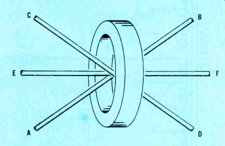
Figure
4 Read-out of the core's condition reverses a logic 1 to a logic 0 state.
Therefore, a third wire carries current to re-establish the former logic
1 state, following a logic 1 read-out (and cancellation). This is called "refreshing" the
stored logic state. E-F REFRESH WIRE RE-ESTABLISHES THE ORIGINAL FLUX.
"But, I am puzzled. What caused the improvement? Have you any ideas?" Mr. Swallow, I doubt that I can solve this completely. But, by studying long hours, attending many classes, interviewing technicians, and working for years in electronics, I now have arrived at the point where I am qualified to guess. So, here goes.
Probably the electrolytic capacitor exploded because you accidentally reversed the polarity of voltage across it when experimenting with the diode. Next, the diode was destroyed because the shorted capacitor connected the diode ACROSS the secondary winding of the transformer.
Part of the welding improvement might be caused by current now flowing during both peaks of the AC voltage. (The rectifier allowed current to flow for only one-half cycle. The capacitor increased the DC voltage slightly, but was much too small in capacitance--compared to the arc resistance--to make the rectification true peak-reading.) I can't even guess what happened to make it better now (with a shorted series diode) than it was originally. Perhaps the overload caused shorted turns in one winding of the transformer, thus changing the turns ratio and the output AC voltage. Or, perhaps the shorted diode added a slight amount of DC resistance that helped the performance at this one set of conditions, by limiting the current.
Those are my guesses, and I'll open the discussion to include you readers.

Figure 5 This welder schematic shows the modifications made by a reader.
More "In Situ"
An "in situ" method of measuring just one of several interconnected resistors was described last March. These in situ measurements are made without disconnecting the component or the wires in a circuit.
With the series parallel arrangement of Figure 6, the ohmmeter connected across R1 will give a wrong reading, until the meter voltage across R2 is bucked out by an external voltage applied across R3. When the same voltage is applied to BOTH ends of R2, the circuit behaves as though R2 is open. This gives the effect of disconnecting R3. Therefore, the ohm meter reads the resistance of R1 alone.
It is necessary to observe a few conditions to make the test accurate and fast. A center-zero meter range allows the balance to be checked by one meter, and without re-connecting any leads.
Many VTVMs can be operated this way, by adjusting the "zero balance" control to place the zero reading (without any voltage input) at the center of the voltage calibrations. Negative voltages read to the left, and positive voltages read to the right of the center zero. The power supply must have an adjustable output voltage, and have regulation over the whole output range.
Select the most-likely ohmmeter range at the beginning, since changing ranges requires a new zero balance.
After the equipment is connected as shown in Figure 6, vary the power -supply voltage in whichever direction moves the meter pointer nearer the zero mark. When the DC voltmeter reads a practical zero, you stop varying the power-supply voltage, and then read the ohmmeter. The ohmmeter will measure only R1, the reading doesn't require any correction or mathematics, and the accuracy will be as good as that of the ohmmeter and the zero-center DC voltmeter.
In most cases, a precise zero-voltage reading is not necessary.
This would waste too much time. A 10% deviation from perfect zero can cause no more than a 10% resistance error. Of course, many resistors are rated at ±20%, and ohmmeters often have errors of 5% or more. The method is not proposed as one giving accuracy to three decimal places. Rather, it is a quick test that can give in-situ readings of "sufficient" accuracy.
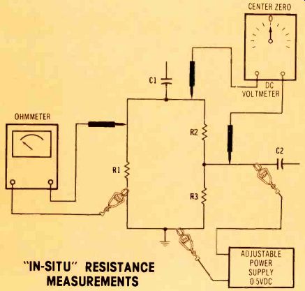
Figure 6 Here is the method of connecting the equipment to measure F11 in
situ (in-circuit), when R2 and R3 in series are paralleled. The power
-supply voltage is increased from zero until the center-zero DC meter reads
zero volts across R2.
With the same voltage at each end of R2, the effect is an open in R2; thus, opening the R2/R3 path.
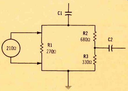
Figure 7. Given these conditions, does R1 have the correct rated resistance?
DOES R1 HAVE CORRECT RESISTANCE?
Alternate method
The popularity of inexpensive hand-held calculators makes possible a combination measurement and calculation of the Figure 6 R1 resistance.
First, the in-circuit resistance of R1 paralleled by R2 and R3 in series is measured. Then, the ohmmeter reading is placed in this simple equation:
R1 = ohmmeter reading times (R2 + R3) (R2 + R3) minus ohmmeter reading For example, in Figure 7, the rated values are: R1 is 270 ohms, R2 is 680 ohms, and R3 is 330 ohms. The ohmmeter reading across R1 is 210 ohms. Is R1 within tolerance?
Using the previous formula, these are the three additional steps:
R2 ± R3 = 680 ± 330 = 1010 ohms therefore, R1 = 210 X 1010 1010 – 210
R1 = 265 ohms
Since R1 is rated at 270 ohms, this is an accuracy of about -2%, which is better than required (in most circuits).
Notice also, that actual wrong resistances of R2 or R3 will make the answer wrong. So, in a way, the method checks all three resistors.
Derivation of the equation
For those of you who enjoy a bit of math, here is the way the formula for finding the resistance of R1 was evolved. The resistance measured by the ohmmeter is called Rx, and the formula becomes:
Rx = (R2 ± R3) R1 R2 + R3
Then, the equation is solved for R1, which produces:
R1 = Rx (R2 ± R3) (R2 R3)- Rx
This is the same as the first formula given for solving Figure 7.
Notice that the same technique can be used to check the ohmmeter reading for any series -parallel arrangement of resistances.
------------
(adapted from: Electronic Servicing magazine, Oct. 1978)
Next: Nov. 1978
Prev: Link |
Also see: