
Answer to Homework Problem
At the end of last month's article, I described a problem for you to solve. You were to design a ripple counter that can count to decimal 11 (binary 1011), reset to zero (binary 0000), count again to 11, reset again to zero, etc. Also, I asked you to use a 4-input NAND gate to reset the toggles, and to avoid including any NOT gates.
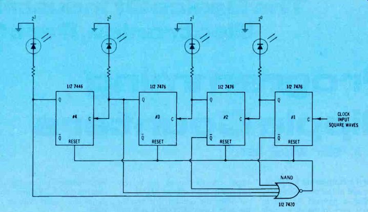
Figure 1 shows the finished circuit. When the count reaches 12 (binary 1100), these are the toggle states:
flip flop toggle 1 is low; Q1 is high.
toggle 2 is low; Q2 is high.
toggle 3 is high; Q3 is high.
toggle 4 is high; Q4 is high.
Because two inputs come from the Q outputs and the other two come from Q outputs, the 12 count brings highs to all four NAND inputs, rapidly switching the NAND output and all four preset terminals of the toggles to low state. Thus, the toggle outputs become low simultaneously for another beginning binary count of 0000. The NAND inputs then are 0011, the NAND output goes high, and the upward count can proceed again.
Notice that all reset terminals should be made high or low at the same time. That's the only certain way of resetting all of the toggles.
As just one of many possible examples, if a low were to be applied only to toggle #1 when the Q output already was low, there would be no change, and the other toggles would not clear.
Reset after the last count
The correct programming of this ripple counter brings up a very important point. Reset MUST occur when the counter first reaches the next count BEYOND the one you have selected as the last count.
For example, suppose you mis understood the "count to decimal 11" instruction, and instead you programmed the counter to reset at decimal 11 (binary 1011). When the counter reached binary 1011, the 1011 readout would be displayed as a LED blink so short your eyes could not see it. In fact, the 1011 display would be present only during the few nanoseconds necessary for the NAND output to go low and all of the toggles to go low.
Visibly, the circuit would count from decimal 0 to decimal 10 and reset to zero.
That's why the short "count" that triggers any kind of change is not listed as a count. So, in Figure 1, the count can proceed as usual from zero to decimal 11 inclusive, with the instantaneous reset occur ring at the beginning of what other wise would have been the decimal 12 count.
Stopping The Count
If the circuit of Figure 1 is changed so the reset terminals all have logic 1 permanently, and the NAND output is connected to either J, or K, or J -and -K of toggle 1, the count will STOP at decimal 12 (binary 1100).
Probably, you remember that a J-K flip flop is made to toggle by connecting both J and K terminals to a constant high. Therefore, if either or both is supplied with a logic 0 signal, the flip flop freezes in the last output state. Flip flops won't change unless the input is negative -going. Without an input signal any toggle stays in the last state.
Therefore, the count of all four toggles can be frozen by stopping only the first flip flop of a ripple counter.
Other counts
By using a NAND with an input for each toggle, you can program a counter to reset or to stop at any number from decimal 0 (binary 0000) to decimal 15 (binary 1111).
(Of course, a limited few numbers can be programmed without any NAND, by connecting the Q or output of one toggle to all reset terminals. The NAND gives more choices.) Use the logic states shown in Table 1 to help you select the correct programming.
Experiment 1: Construct the circuit of Figure 1, and test it by noting that it counts from 0000 to 1011, resets to 0000, and counts up again.
Experiment 2 Rewire the Figure 1 circuit so it will count to 1100 (decimal 12) and then stop at 1100 until reset. Figure 2 gives the schematic. After being reset, the circuit should count up to 1100 again and stop there.
The reset of Figure 1 is accomplished automatically, when the count reaches the programmed number. In Figure 2, the resetting is done by a manually-operated switch.

Figure 1. This circuit will begin counting at 0000 (decimal 0), and count
up to display 1011 (decimal 11) before it resets to 0000 and begins counting
up again. The sequence is repeated as long as the circuit has power and input
signals.
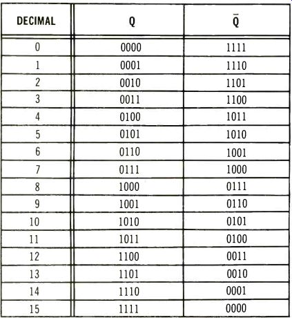
Table 1 Use this handy table to help you design, program, or test these
4-digit counters.
In Figure 1, the NAND output is connected to all of the reset terminals, while Figure 2 has the NAND output feeding only the K terminal of toggle 1. Therefore, when the 1100 count is reached, the counter is stopped, but is not reset until the manual switch is turned to logic 0.
Test the modified circuit by ob serving that the count proceeds up to decimal 12, where it stops.
Changing the switch to the logic 0 position should reset the counter to 0000, then after the switch is returned to the logic 1 position, the upward count should resume until it stops at 12. Verify that these actions do occur.
Counting Down
Table 1 also shows another important fact about ripple counters. The Q column counts up from decimal zero to decimal 15, as it is read from top to bottom.
Notice that the Q column (from top to bottom) counts DOWN from decimal 15 to decimal zero.
Therefore, the basic circuit of Figure 1 can be used to count down, if the LEDs are connected to the 0- outputs of the toggles, rather than the Q outputs.

Figure 2. Rewire the Figure 1 circuit as shown here so it will count up
to 12 and stop until the manual switch is turned to logic zero and back to
logic 1. After the switching, the circuit again counts to 12 and stops.
Experiment 3. Wire the Figure 3 circuit. But, before you apply power to it, determine at which decimal number the counter will reset to decimal zero.
Check your answer at the end of this article, then verify the operation by watching the circuit count.
Troubleshooting
Question 1
Answer the following questions about the circuit of Figure 4:
(1) Does the circuit count up or down?
(2) Is the counter designed to stop at a certain number, or start again at 0000 after a certain number is displayed?
(3) If it resets after a certain number is displayed, what is that number?
Experiment 4
Construct the circuit of Figure 4, and verify the answers to Troubleshooting Question 1.
Don't disconnect the wiring, for the counter is part of the next experiment.
Decoders and Readouts
All counters operate by binary numbers (highs and lows in combi nation), but such numbers are not convenient for many uses.
Decoders can be used to translate the binary count into some desirable decimal-number count. The type of decoder that's used most often incorporates a 7-segment decoder which controls the individual bars of a 7-segment display (LEDs or liquid crystal).
The block diagram of Figure 5 shows a decoder with a display.
Toggled flip flops (such as those in Figure 1, except programmed to count only between decimal 0 to 9) furnish the four input signals to the decoder. From the decoder, seven output lines control which of the 7 readout segments are activated.
Figure 6 shows how decimal numbers from zero to nine are formed by combining segments of the display.
Typical Decoder and Readout
The wiring diagram for a 7447 decoder and a typical 7-segment LED readout is shown in Figure 7.
The inputs marked 1, 2, 4, and 8 are to be connected to the same numbers at the top of Figure 4.
Output terminals of the decoder numbers, and the corresponding segments of the display are given the same numbers. The resistors are required to limit the current to a safe value.
When the output terminal of the decoder goes low, the corresponding readout segment lights. All of the LED anodes are paralleled and wired to +5 volts.
Test the readout by momentarily grounding the "lamp test" terminal. All 7 segments should light, forming the number 8. If any fails to light, the wiring is wrong, or one of the devices is defective.
Experiment 5. Wire the circuit of Figure 7, and connect it to the Figure 4 counter.
Note: it is not necessary to disconnect the LEDs.
When power is applied, the total circuit should count from decimal 0 to decimal 6, then reset to 0 and count to 6 again, etc.

Figure 3. As it is programmed, should this circuit count up or count down?
What decimal number will reset the counter?

Figure 4. Use the diagram to answer three troubleshooting questions.
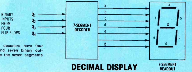
Figure 5. Many decoders have four binary inputs and seven binary out puts
which drive the seven segments of a display.

Figure 6. Readout segments can be lighted to form simulations of all decimal
numbers from 0 to 9.
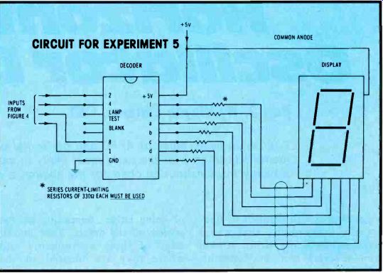
Figure 7. Wire this decoder and display system to the counting circuit of
Figure 4.
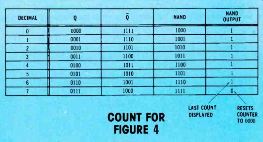
Figure 8. These are the binary counts for the circuit of Figure 3.
Answer to Experiment 3
As it is wired, the circuit of Figure 3 should count down from decimal 15, then reset instantly when the count reaches binary 1100.
Figure 8 shows that, starting at decimal 15, only three counts occur before 1100. They are: 1111 (decimal 15); 1110 (decimal 14); and 1101 (decimal 13). The next down count is 1100 (decimal 12), and the counter will reset to decimal 15 before the 1100 binary readout can be seen.
Answers to Troubleshooting
Question 1
(1) The circuit will count up, because the LEDs are connected to the Q -output terminals of the toggles.
(2) The counter is designed to reset to 0000, when the count reaches the programmed number. Notice that the NAND output goes to all four reset terminals.
(3) Reset will occur when the binary number 0111 (decimal 7) is reached.
Thus the highest number that can be displayed is binary 0110 (decimal 6).
(adapted from: Electronic Servicing magazine, Oct. 1978)
Next: Part 17 (Electronic Servicing mag., Nov. 1978)
Prev:
Also see: Sam Wilson's Technical Notebook