By Homer Davidson
Although no single article can describe all possible defects in car radios and tape players, these case histories should help you solve many similar problems in other models. Also, suggestions are given for trouble shooting tests and general methods.
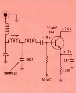
Figure 1---Audiovox model AMF-15 had no AM-band operation.
Solid-state auto radios are not very difficult to repair. Some circuits are in cramped corners, and there are some accessibility problems. Also, many machines will require removal of dust and dirt before you can see the components.
Other problems should be no more severe than those in home radios.
The following case histories should help you anticipate some of the typical troubles.
Dead AM reception
No sound could be heard on either the FM or AM bands. Voltage measurements around the power section of the circuit board revealed that no voltage was reaching any circuits. While tracing the supply voltage from the on/off switch to the filter capacitors, I found an open in the printed wiring.
The open wiring was bridged by a piece of hookup wire soldered over the printed wire. The FM radio operated on all the usual stations, but the AM function was completely dead.
Now, the IF transistors are common to both AM and FM, so it was obvious that the problem must be around the AM input stages, such as the RF or oscillator.
An in-circuit test of RF transistor TR4 showed a beta reading without any opens. Voltage readings, too, were quite normal. But when any of the transistor leads was touched, strong local radio stations could be heard. Obviously, the defect was in the RF stage.
A generator signal was injected at the base when the radio was tuned to 1400 kHz and the gain seemed to be normal. The same signal applied to the input jack could not be heard. The signal was injected in turn to each end of the 0.01 coupling capacitor, and it gave normal volume.
The defect had to be between the input jack and the 0.01 coupling capacitor (Figure 1). Ohmmeter tests of the few components found that the 0.0022 bypass capacitor was shorted. A new capacitor restored correct AM sensitivity.
Motorboating and oscillating
A mixture of oscillations and motorboating was the complaint against the model 706A Dodge radio.
Most complaints of this nature are caused by open filters or bypass capacitors. Occasionally, bad transistors or improper alignment will do the same.
All filter and bypass capacitors were paralleled in turn by another capacitor of a larger value, but the problems continued.
Generally, transistor testing and voltage measurements are not effective for locating components that produce oscillations. The squealing could be heard as the radio was tuned across each station, so we suspected a bad converter bypass capacitor.
However, in making the tests, the meter probe was touched to the emitter of the RF transistor (Figure 2) and the radio played weakly but without oscillations.
The .01 emitter bypass capacitor was replaced, and the performance was very good.
Intermittently weak reception
When the American Motors model 2HT1413, radio became intermittent, only two local stations could be heard at all. However, the radio would rapidly alternate be tween normal sensitivity and this weak condition.
Because there was no overload of local stations during the weak periods, we assumed the problem was in the RF stage. Very low do voltage was measured at the base of Q1 (Figure 3) and none at the emitter. These readings indicated that Q1 was not conducting.
However, an in-circuit test of Q1 showed a good beta reading and no opens. Sometimes an intermittent transistor will "pop" on when a transistor tester is connected, so we always make additional tests. The suspected transistor was replaced with a universal SK3018. Unfortunately, within minutes, the intermit tent began again.
After several unsuccessful tests, we measured the resistance of all transistor leads to ground. Such tests generally are not accurate with the transistor still connected. But this test showed about 200-o from emitter to ground and only about 3-o from base to ground.
We replaced the 47-uF base-return bypass capacitor and the intermittent was cured.
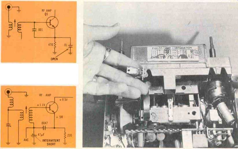
Figure 2 Motorboating and oscillations ruined reception of the model
706A Dodge radio.
Figure 3 Intermittently, the model 2HT1413 American Motors radio would become very weak. Only two stations could be heard.
Figure 4 Excessive current drain in the Philco-Ford model DOAA-18806 indicated a shorted output transistor. In this model, part of the dial assembly must be removed to gain access to it.
One local station
Only the local 540-kHz radio station could be heard at the low end of the dial, and nothing (not even noise or static) was received above about 700 kHz.
When only the low end stations can be received, we usually find the converter transistor is not oscillating over the entire band. In this case, a replacement converter transistor didn't solve the problem.
Analysis of the dc voltages showed a supply voltage of slightly above 6V (it should have been 12V or higher). And the small bench-mounted power supply was running hot and buzzing. We suspected the audio power-output transistor, which has its mounting screw located inside the dial assembly. After we unsoldered the transistor leads, the supply voltage rose to the normal 12V.
Before the power transistor could be removed, it was necessary to remove four plastic inserts from the dial assembly. To remove each insert, take out the round center core and then pry out the plastic insert. Next, remove two metal screws that hold the metal dial assembly. The mounting screw for the transistor now is accessible.
After the output transistor was removed from the small circuit board (see photo in Figure 4), a leakage test verified that the transistor had nearly a dead short. A universal SK3041 was used to replace it.
Before you solder the new leads, make sure the flat side of the transistor is opposite the lead wires.
Then, double-check the wiring. Yellow wire goes to the emitter, the blue wire to collector and the green wire to the base. After the transistor and small circuit board are fastened into position, a drop of silicone-rubber cement should be added to prevent the board from turning.
Severe noise
A model CYM62 Motorola had very noisy reception, and occasion ally the audio would stop for a short time.
Generally, such noise is caused by bad transistors, worn volume controls, leaky IF transformers, and leaky RF or oscillator padder capacitors. And sometimes a defective ceramic capacitor or noisy resistor in the audio stages can produce a similar noise. Of course, audio noises can be heard all the time, but RF and IF noises vary in loudness with the volume control settings. Thus, the volume control divides the radio for test purposes.
In this case, the noise originated before the volume control.
One shortcut for finding noisy transistors is to short the base to its emitter. Do this to each stage. If the B/E short stops the noise, the noise source probably is in some stage upstream. By using this method, we noise to the converter stage.
Sometimes the circuit where the problem originates will show a fluctuation of dc voltage when the noise is loudest. This was true of the converter emitter voltage, and we concluded the defect was close by (Figure 5). Because nearly all of the supply voltage appears across the oscillator padder capacitor, it was suspected of erratic leakage.
When the capacitor was disconnected, a varying high-resistance reading. was obtained across the terminals. Installation and adjustment of a new padder solved the noise problem.
Low audio gain
Only one radio station could be heard, and it had weak volume.
These symptoms in a model 986846 Delco might make you suspect an RF, converter, or IF problem. This suspicion was strengthened by a normal amount of buzz, when a screwdriver blade and finger were touched to the center lug of the volume control.
Using a noise generator, the signal was traced to the second-IF transistor. When the signal was applied to the base, the sound was very weak, but it was loud when touched to the collector. An in-circuit transistor test indicated the transistor was open, and the installation of a replacement restored the proper volume and number of stations.
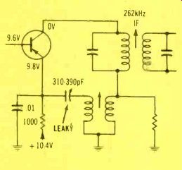
Figure 5 Severe noise in a CYM-62 Motorola was traced to a leaky padder
capacitor.
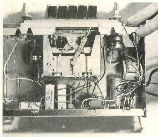
Figure 6 Both volume controls and the switch were pushed back out of
position, and several wires were broken in the Craig model 3521 radio.
Broken volume control--The complaints against the Craig model 3521 radio and cassette player were no sound and a loose volume control.
A visual examination showed the frame of the volume control was firmly attached to the radio, but both volume controls and the switch were pushed backwards so they rotated with the shaft. This improper movement had broken the power lead from the on/off switch.
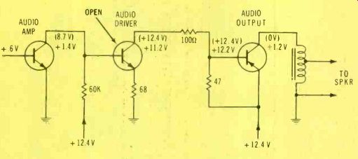
Figure 7---No click or thump could be heard when this inoperative Motorola
TM7A was turned on. Usually a power problem or a dead output transistor
is responsible.
The customer was ready to start his vacation and there was no time to order the special control assembly. Therefore, the control was fastened together (with spots of solder strengthening the tabs), the power wire and ground leads were re-soldered, and the radio worked fine except for the noisy volume controls (Figure 6). We ordered the volume-control assembly for installation after his vacation.
Some noisy volume and tone controls can be restored by squirting tuner spray inside and then rotating the shaft several times.
Other controls either don't become quiet or the noise elimination lasts only a short time. So, it's best to consider cleaning as a temporary remedy that might last until a new control can be obtained.
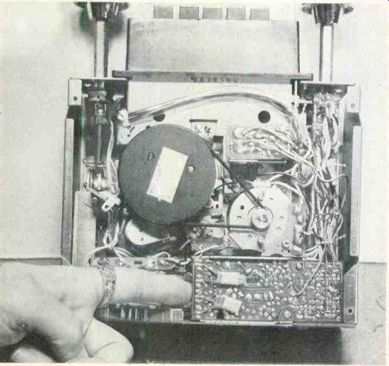
Figure 8---A poorly-soldered joint produced one weak stereo audio channel
in a Sanyo FT872.
No sound---When this Motorola model TM7A was brought in, no station could be received and no click was heard when the radio first was turned on. (If the output stage is operating, most radios will have a thump or click.) With these symptoms, the output transistor usually is dead. We replaced it, but there was no change (Figure 7).
An audio tone was injected at the volume control, but not a sound came from the speaker. Next, dc voltage readings were taken in the audio system. The emitter voltage was zero, the base had 8.7 V, and the collector measured the same as the 14.2 V supply. There was no C/E current, and yet the forward bias was 8.7 V. Obviously, the B/E junction was open. This was verified by an in-circuit transistor test, and a new transistor restored the good performance.
One weak channel---One channel of the Sanyo FT872 was very weak, but there was no distortion. In this combination radio and Stereo-8 player, the audio stages are on a separate circuit board, as shown in Figure 8.
Where two identical stereo channels are used, a very effective troubleshooting technique is to compare the voltages and signal level of the bad channel against the good one. Therefore, a signal from an audio generator was injected at each stage of both amplifiers, starting with the output and working upstream. Source of the weak signal was found between the first and second audio transistor.
When the signal was injected at the input side of the 10-uF coupling capacitor, the sound usually was weak, but at times it snapped back to normal volume. At first, we thought the capacitor was intermittent, but a loose soldering joint was found at one end of the capacitor during the start of disconnecting it.
A good soldering joint stopped the intermittent and brought back proper gain to the weak channel.
Intermittent transistor---At first, we suspected an IC audio amplifier in the model CKL 4019 Automatic radio. However, voltage checks and other tests changed our suspicion to the audio output transistor (see Figure 9).
When the meter probe was touched to the transistor leads, several times the sound would begin. There was no noise and no stations when the radio was malfunctioning.
When the sound was not working, the collector voltage was zero, the base voltage was 10 V and the emitter measured 12.8 (the supply voltage). These voltages indicate no transistor current and an open junction. Replacement of the intermittent output transistor with an SK3041 transistor cured the problem.
Both stereo channels dead
Both channels of the model KID-565 Kraco radio and tape player were dead. This is unusual.
Usually the two channels have different symptoms, even if both have problems. Of course, power-supply defects can kill both channels at the same time.
In this case, the audio power ICs of both channels were nearly shorted (Figure 10) and required replacement. Shorted speaker wires might have caused the ICs to fail.
Before you remove any ICs, check for mounting arrows or identification numbers. It's difficult to determine the right position otherwise.
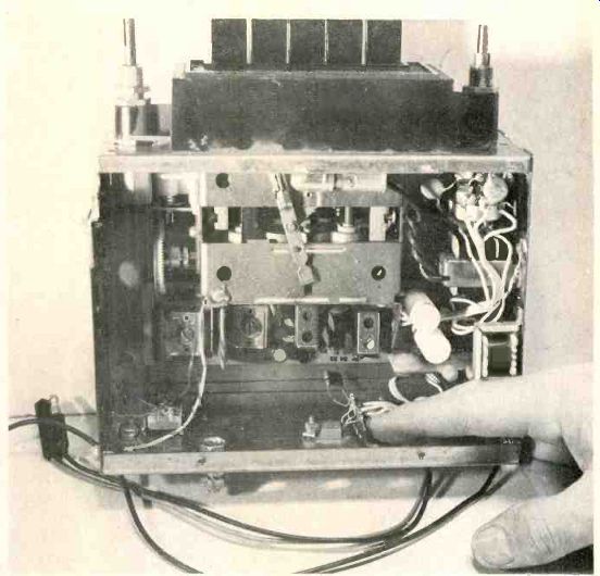
Figure 9-- This model, CKL-4019 Automatic radio had intermittent volume.
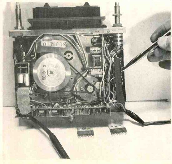
Figure 10 Both stereo channels of the Kraco model KID-565 were dead;
an unusual symptom, except for power-supply problems.
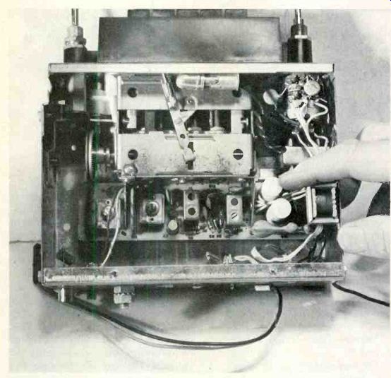
Figure 11. An ear-splitting shriek was the symptom of the radio. Filter
capacitors often cause this trouble.
Loud shrieking noises
Radio stations could be tuned in however, volume of the sound was not changed by the controls. But the most obvious symptom of the model 7985773 Delco was the ear-splitting shrieking noise.
Noises of this kind often are caused by open filter capacitors (shown in Figure 11). Test for the possibility by shunting a 1000-uF 16-V capacitor across each filter in turn. If the test capacitor stops the shrieking noise, the capacitor it was paralleling at the moment is the open one.
Sometimes several capacitors are located in one container. If just one section is open, it's best to replace the entire assembly.
One filter capacitor was replaced and all abnormal noises were gone.
Motorboating
When the volume control of the Delco model 01BP2 was advanced, the sound would develop a fast variation of volume (often called motorboating). Also, the dc voltages at the filter capacitors would vary in step with the motorboating.
Each filter was shunted by a test capacitor. Paralleling the test capacitor across one certain filter capacitor stopped the motorboating (Figure 12). This was in a multiple-capacitor can, so the whole assembly was replaced. All motorboating was eliminated.
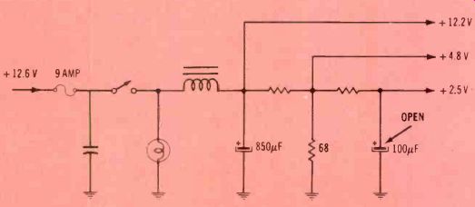
Figure 12---Motorboating commonly is caused by open filters. This was
true of the model 01BP2 Delco radio. Several capacitors were in one
can, so the can was replaced, rather than just the one bad section.
Comments
As you can understand from these actual case histories, not many auto-radio repairs are difficult. As always, intermittent problems bring additional complications. But, the techniques of signal injection and dc-voltage analysis usually can pinpoint the stage that has the trouble.
Some defects are more likely to occur than others. Capacitors often become intermittent; resistors seldom do. And symptoms vary ac cording to the circuit having the defect. You can save hours by knowing these facts.
Before you install the covers after a repair, check the pilot lamps and replace them if necessary. Use window spray to clean out any dirt or grease from the dial assembly.
Adjust all pushbuttons correctly for local radio stations. These chores require very little time, but they will impress the customers with your helpful attitude.