By Gill Grieshaber, CET
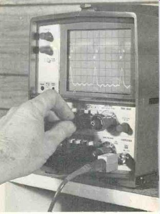
---- Many of the illustrations were taken from this Tektronix model T935, a 35-MHz scope which is suitable for all types of electronic servicing.
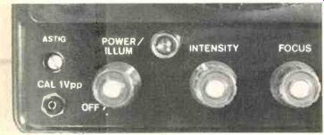
Figure 1 After the power is turned on, the intensity is adjusted above
mid point and the positioning controls are rotated to their center, a
recurrent scope should show a horizontal line even without an input signal.
In comparison, a triggered scope shows no horizontal line or waveform
until it's triggered (or automatic triggering is in operation).
Hours of diagnosis time can be saved if a good scope is used for all service problems that involve waveforms. This is especially true when the scope is stable, easy to use and has all of the needed features. The following suggestions provide both old and new tips about valuable uses for scopes.
The new oscilloscopes have much better specifications, can perform more functions, and operate almost automatically. They are a pleasure to use. However, they require an operator who knows which of many functions should be used for each measurement. Neither can the scope interpret the waveforms. The opera tor must do that.
So, this information is directed to all scope operators, for it tells about the many jobs these scopes can do (some are not common knowledge) and how to adjust the scope to receive the right results.
Illustrative photographs were taken of the Tektronix model T935 and an older B&K-Precision model 1470. These models are pictured merely because the manufacturers volunteered to loan them for the article. However, other triggered scopes are similar, and the pictures should identify the various controls and their names.
Instantaneous graphs
Each oscilloscope display is an electronically drawn graph of amplitude versus either time or frequency. The most significant difference between recurrent and triggered scopes is that recurrent sweep operates at a repetitive frequency. Triggered scopes sweep for an adjustable period of time.
Examined in a superficial way, this distinction doesn't appear to be very important. If the waveforms are the same, who cares how they are formed? However, triggered scopes can perform functions and display waveforms that are impossible for recurrent types.
Recurrent sweep
The horizontal sweep of all scopes must be synchronized with the signal. In general, many unstable oscillators (such as the horizontal oscillator in a recurrent scope) can be locked to a standard signal by injecting into the oscillator a sample of the standard signal. Also, the oscillator can be locked to a sub-multiple of the signal. This is a type of direct sync which works fairly well when all conditions are optimum (and certain limitations are accepted). Unfortunately, it's often an unstable balance between compromises when used in scopes.
It is easy to show a line on the CRT screen. Apply the power, turn up the brightness (Figure 1) and usually there is a horizontal line, even without anything connected to the probes. The focus control can be adjusted after a waveform is obtained; it has no effect on the brightness. Then the probes are connected to a source of signal. The vertical, sweep and sync knobs are turned until some kind of a waveform appears on the screen. A touchup of all adjustments completes the procedure.

--------- Figure 2 One limitation of recurrent scopes is that they
can show only complete cycles, and relocking is required to obtain a
different number.
Beginning with a single sine wave (top trace of A), a CCW rotation of the frequency vernier to a lower frequency breaks the lock, and the waveform moves rapidly (center trace of A).
Additional rotation locates another locking spot with two sine waves (bottom trace of A). Another CCW adjustment gives a false locking with two separate waveforms (top trace of B). Finally, more rotation of the frequency control results in three complete sine waves, as shown by the center trace of B. More sine waves may be obtained by additional CCW rotation (bottom trace of B).

------- Figure 3 A triggered-sweep scope can be adjusted for any fraction
of one cycle or almost any number of cycles.
Within the range of the variable sweep-time control this change in the number of cycles is continuous. No relocking is required.
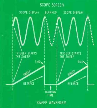
---------Figure 4 With a triggered scope locking the waveform is done
by proper triggering, not by locking an oscillator (it doesn't have an
oscillator). The "level" control is adjusted for a certain
voltage. When the signal voltage reaches this voltage level, the trigger
circuit starts the horizontal sweep. In the drawing two groups of sine
waves show the signal displayed during two horizontal sweeps while the
sawtooth waveshape below is the horizontal-deflection waveform.
Adjustment of the "time/div" switch has programmed the sweep to operate for a specific length of time. When that time has elapsed, the sweep stops and retraces rapidly. In this case, the sweep occurred during slightly less than two complete cycles (and only that much of the waveform is displayed on the CRT screen). Then the triggering circuit waits (with the CRT brightness blanked) until the signal waveform again reaches the programmed triggering-voltage level.
Length of this inactive time depends on the waveform; it might be short or moderately long. Next time the signal amplitude reaches the programmed point the sweep is triggered for another timed deflection (showing almost two cycles again). At the end of that sweep time, retrace occurs and the waiting time begins. This is the operation during two sweeps. Triggering can occur only when one more condition is satisfied: the right signal-voltage level must be reached when the signal slope is positive-going or negative-going, according to the way the "slope-level" switch is adjusted.
However, if the signal frequency varies as little as 10%, the wave form jumps out of lock. Also, there are more limitations.
Figure 2 shows the sequence of waveforms obtained by changing from a locked single cycle of sine wave to two or more locked cycles.
Notice that no usable waveforms are obtained between the locking points. The long retrace of recur rent sweep removes a significant part of the single cycle at the top of picture A. When the variable frequency control is turned toward a lower frequency, the waveform jumps out of lock and becomes a blur (center trace of A). Additional careful rotation of the frequency control brings in two cycles (bottom trace of A). Again the knob is turned CCW for a lower frequency and a point of false locking (with two superimposed waveforms) is obtained (top trace of B). More rotation brings a locked waveform of three cycles (center trace of B), and finally four cycles can be obtained (bottom trace of B). Of course, two cycles result when the sweep frequency is exactly half that of the signal frequency.
Notice that it's impossible to obtain less than one cycle (or anything except complete cycles) with recurrent sweep. By contrast, Figure 3 shows that any number of cycles or fractions may be obtained easily with triggered sweep.
Triggered sweep
Locking the waveform of a triggered scope actually is accomplished by proper triggering. The triggering circuit is adjusted for a certain voltage level. When the vertical signal reaches that preselected voltage, the trigger is activated, and this "triggering" starts the horizontal sweep which then continues for a certain period of time (selected by the scope opera tor). At the end of the sweep time, the sweep stops, retraces instantly and waits in an inactive state until it is triggered again by another section of the signal that has the same polarity and voltage (Figure 4).
The length of time spent in the inactive or waiting mode is deter mined primarily by the character of the signal, and is affected indirectly by the sweep time, but not at all by the scope design or its adjustments.
If the proper triggering voltage arrives immediately after the previous sweep has stopped, the waiting time is short. If the end of sweep and the triggering voltage point are separated by a considerable space on the waveform, the waiting time is increased comparably.
Not super-sensitive-The triggered sweep is not a delicate balance which is upset by minor variations.
Two items contribute to the stability after locking is achieved.
One is that minor variations of the sweep time have no effect on the locking (because the next triggering does not depend on the end of the previous sweep). This is not true of recurring sweep, for the slightest variation of signal duration or repetition will destroy the locking.
Also, it's easier for a triggered scope to find a programmed voltage level in most any kind of signal waveform than it is for a recurrent scope to find a compatible frequency.
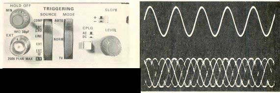
Figure 5 This area contains the triggering controls. The "source" switch
selects the origin of the signal that is to supply the triggering voltage.
At the left is the "ext" socket for bringing in either external
signals to be used for sync or a signal for the X-Y mode. Forget about
the "hold-off" knob. It's used only with certain kinds of pulse
trains. A choice of "auto" (free running) triggering, "normal" triggering
or a "TV" sync separator combined with auto triggering is given
by the "mode" switch. The "cplg" switch selects either
ac or dc coupling of the trigger signal. The "level" and the "slope" polarity
controls together select the voltage point where sweep triggering occurs.
Other scopes have more or fewer controls but the operation is similar.

Figure 6---When this one kind of automatic triggering is used, the appearance
(top waveform) with a locked signal is conventional. But when there is
no input signal the circuit supplies a free-running oscillator that furnishes
a base line. Or, if the waveform is not properly triggered, an out-of-lock
display will be seen (see bottom waveform). This helps by indicating
a waveform is there but is not locked. (Normal trigger operation allows
no line or waveform unless the triggering is right.) Auto operation in
other scopes might affect the triggering in different ways so consult
the instruction book that comes with the scope.
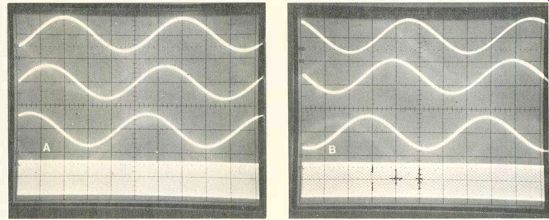
Figure 7--When the slope-polarity switch is in the "+-" position,
proper locking can be obtained at any point on the positive-going slope
of a waveform except near the peaks.
When the trigger-level control is turned to start the triggering too near the tip the locking becomes unstable.
And when it's adjusted at or beyond a peak no locking is possible. (B) The same operation applies to the '-setting of the slope-polarity switch, except the triggering is on the negative-going slope.
The lineup of triggering controls in Figure 5 seems complicated. But all except two can be preset.
Duties of the "source" and "mode" controls often are divided differently with more or fewer knobs. For the pictured scope, the "source" switch selects the origin of the triggering voltage, such as Channel 1, Channel 2, 60-Hz line or external. This triggering voltage often is taken from the vertical signal, but it can come from another signal of identical repetition rate. For example, video wave forms can be triggered (locked) dependably by selecting a vertical-sweep or a horizontal-sweep wave form that's brought in through the external-input jack.
Not all scopes have two functions provided by the "mode" switch. In the "auto" position, the sweep operates as a free-running oscillator. So the screen shows a horizontal line across the screen with no signal, or an out-of-lock waveform if the signal is not correctly triggered. "Normal" mode is the one all triggered scopes have.
Without correct triggering (locking), there is no sweep or any brightness on the screen.
"TV" position of the mode switch connects a sync separator (similar to those in TV receivers) that supplies vertical and horizontal sync to the triggering circuit. Triggering then occurs from this sync, and not from a voltage level of the video. I highly recommend the TV sync feature because video is very difficult to lock properly without it (especially at vertical rate).
Incidentally, the auto mode al lows the locking of a triggered scope to be done very much as though it is a recurring type.
Without proper triggering (locking), the waveform moves rapidly across the screen. When normal triggering is achieved, the waveform is steady as though locked. Present users of recurring scopes and beginners will like the auto feature.
In Figure 6, the upper trace of sine waves is being triggered properly (call it locked), while the bottom trace shows loss of triggering but with a sweep supplied by the automatic circuit (call this unlocked).
Level and slope controls--The "level" control adjustment determines the voltage level that triggers the sweep (there is no oscillator). There fore, it is the principle means of obtaining a stable waveform. The "slope" switch selects either the positive-going slope or the negative-going slope of the triggering signal.
This is similar to the toggling or enabling of digital circuits where the action occurs only at the leading or trailing edge of the driving waveform.
Separate controls for these two functions allow the operator to select which slope causes the triggering (and also which slope is seen at the beginning or left edge of the waveform).
Range of the level control--Follow the next discussion carefully, for it will explain why an amplitude change sometimes ruins the locking, and how to obtain displays that are more stable.
Figure 7 shows the broad range of non-critical adjustments for correct triggering (locking) of sine waves. Only the slope switch and the level control are adjusted for the sequence.
For the waveforms in Figure 7A, the slope switch remains in the "+" position. A level control adjustment that causes triggering on the positive slope near the negative peak's tip is shown by the top trace of A. In the next-lower trace, clockwise rotation of the level control has moved the triggering point up to the waveform's vertical center and moved the cycles to the left. Continued clockwise rotation (see next-to-bottom trace) moves the triggering point up near the tip of the positive peak while the cycles again are moved to the left. (This sideways movement of the sine-wave cycles is very noticeable when the sequence is done rapidly.) Finally, a slight additional clockwise rotation of the level control eliminates the triggering (locking), and the auto-sweep operates to show the wave form as a moving blur (bottom trace).
For the Figure 7B waveforms, the slope switch is changed to "-" position. Continuing from the previous explanation, a slight CCW rotation of the level control brings the stable waveform of the top trace, with triggering occurring on the negative slope near the positive peak. More CCW rotation of the level control moves the cycles to the left and begins the trace near the vertical center of the waveform (next-to-top trace). Another CCW rotation of the level control moves the triggering point down near the bottom of the negative slope at the negative peak, and also moves the cycles to the left (next-to-bottom trace). Finally, a slight additional CCW level control rotation eliminates the triggering, and the bottom trace shows the loss of locking that indicates the auto-sweep is showing a rapidly moving signal.
This sequence is difficult to describe in words and probably sounds very complicated, but it can be done simply and easily. I strongly recommend that you try it for yourself; it will clarify the triggering operation.
The main point of Figure 7 is to show that the triggering point may be selected anywhere along either slope and provide stable triggering (locking), except near both positive and negative peaks. If the level control is adjusted for a voltage that's above or below the waveform, no triggering is possible regardless of other adjustments.
Arranging for stable triggering
It's possible and desirable to preset the level control to a position that makes proper triggering almost a certainty with sine waves.
Refer to the A picture of Figure 8. Begin by adjusting for a stable large sine wave that has its triggering point about a third of the amplitude down from the positive peak as shown. Now, slowly reduce the vertical gain and notice that proper triggering (locking) is lost when the amplitude drops barely below the triggering point. No part of the signal extends up to the voltage selected as the trigger.
Therefore, triggering cannot occur.
Figure 8B changes the conditions slightly. Again, display the same original sine wave amplitude as before, but rotate the level control to place the triggering point as close as possible to the zero point at the vertical center of the wave form. This time when the amplitude is reduced, correct triggering is maintained almost to zero amplitude.
Therefore, when first trying to obtain any kind of waveform, adjust the level control to the exact center of its action. This center can be found as in Figure 8B by rotating it to the point that places the sweep starting point at the center of the signal amplitude.
Perhaps a pointed small bit of masking tape could be stuck there to mark the center.
This small precaution will speed up finding a triggering point regardless of the waveform or its amplitude. When the best method is used, correct triggering (locking) can be done much faster than with recurrent scopes. And the stability is far superior. For example, after it has been triggered to a certain signal, the scope can be turned on and off repeatedly (even off for hours) and at each turn-on, the waveform again will be "in lock" without needing adjustments. Or, the signal frequency can be changed radically; the number of cycles displayed will be different, but no triggering adjustments will be required, variations found in different models.
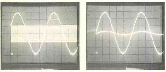
--------Figure 8 Triggering is not possible when the signal level drops
below the voltage level selected by the trigger-level control. (A) When
the trigger level was about three-fourths up the slope, the triggering
was eliminated when the signal amplitude was reduced below that point.
Of course, auto triggering showed an out-of-lock waveform. (B) However,
when the triggering point was adjusted to the vertical center of this
symmetrical waveform, a larger reduction of level did not disturb the
triggering (locking).

----------Figure 9 In the B&K-Precision the "sweep-time/cm" switch
supplies sweep between 100 ms and 1 us. The variable knob gives an uncalibrated
but true increase of sweep time. In addition, a fixed X5 horizontal magnification
can be switched in to give the effect of a 5-times decrease of sweep
time. These are only two of the variations found in different models.

--------Figure 10 Changing the sweep 'time to give a different number
of cycles does not affect the triggering (locking). (A) When two sine
waves were triggered at the vertical center, the sweep time could be
increased by 10 times (top) or decreased by 10 times (producing only
a slope as shown at the bottom) without loss of locking. (B) In the same
way triggering with the sweep-time too short shows only a line which
tilts, becomes a curve and finally develops into a sine wave as the sweep
time is made longer. Resetting of the triggering is not necessary.
Selecting sweep time
As mentioned before, sweep time is not a factor in proper triggering.
A different sweep time changes the number of cycles on the screen, nothing more. Of course, the nearness of triggering and sweep-time switches on the panels of most scopes probably gives a false impression that their functions are related.
Every triggered scope has a knob labeled "sec/div," "sec/cm," or "sweep-time/cm." The figures be side each switch position (see Figure 9) represent the amount of time (in seconds, milliseconds or microseconds) required for the writing beam to travel horizontally between any two adjacent graticule lines (one division or one centimeter).
For example, the switch in Figure 9 is turned to the 10 us position (one of the best sweep times for horizontal-frequency TV wave forms). Each division or centimeter of the graticule is swept for a time of 10 us. The entire width of the graticule requires a sweep duration of 100 us.
Two examples of various sweep times are shown in Figure 10. The center trace of Figure 10A has two sine waves that were properly triggered and swept at a 2 ms time.
Then, without any adjustment of other controls, the time/div switch was turned to 20 ms, and the screen showed 20 sine waves (top trace). Next, the switch was rotated for a short 0.2 ms, producing a waveform (bottom trace) that resembled a crooked line. Actually, it was about one-fifth of a cycle.
Triggering was not interrupted because the level control had been set to place triggering at the vertical center of the waveform.
In the Figure 10B picture, the time/div knob for trace 1 was set to a sweep time that was too short for the signal frequency, and the display was nearly a straight level line. For trace 2, the next slower sweep speed was selected. Another slower speed showed a curve (the quarter cycle in trace 2). Finally, the scope operator moved the switch two positions slower and a nearly complete single sine wave was revealed. Slower sweeps would have produced more cycles.
Notice that the triggering occurred (and the sweep began) at the same point each time.
For unknown signal frequencies, sequentially adjust the amplitude and the various trigger controls until any kind of stable display is obtained. Then vary the sweep time to produce a manageable number of cycles on the screen.
A beam finder is helpful if no waveform can be seen. Excessive gain with square waves, for exam pie, might drive the tips off of the screen. And of course, unlocked square waves appear to be two parallel horizontal lines on the screen.
In addition to the time/div switch, all triggered scopes have a variable-sweep control. Some have a concentric knob that provides calibrated sweep time when it's turned fully clockwise until a switch clicks.
When rotated to the left, it in creases the sweep time; however, the amount is not known. For many measurements, the exact time is not critical. But whenever maximum accuracy is needed, the control must be turned to the calibrate position.
Another feature of triggered scopes is an optional widening of the horizontal sweep. When an X5 magnification switch is turned on, the width of the horizontal sweep is increased to five widths. Repetition rate of the sweep is not changed, and neither is the sweep time.
However, the beam travels five times as far in this same time, so the effect is nearly the same as dividing the sweep time by 5. In effect, 1 us has become 0.2 us, for example. Illustrations will be given next month.
There are a couple of differences.
The other four-fifths of the sweep continues to operate, but it's off the screen. Any portion of this expanded waveform can be seen by adjustments of the horizontal-positioning control. There is one trade off. Because the trace is on the screen only one-fifth of the time, the visible trace has less brightness.
Of course, that's another reason to choose a scope that has too much brightness when used for non-magnified waveforms.
Next month--Some of the important topics in Part 2 next month include the operation and calibration of probes; how to use time-base calibrations to measure frequency (including TV vertical and horizontal); the time settings for often-used frequencies; how alternate and chopped modes of dual-trace work; how to measure rise time and look at the VITS and VIR signals; how to measure dc voltages and a mixture of dc and ac; and many other measurements and analysis of waveforms.
Also see: Better waveforms with wideband scopes