Each report about an item of electronic test equipment is based on examination and operation of the device in the ELECTRONIC SERVICING laboratory. Personal observations about the performance, and details of new and useful features are spotlighted along with tips about using the equipment for best results.
By Carl Babcoke
Model 1479 oscilloscope from B&K-Precision has many advanced features including dual-trace operation, 30MHz vertical bandwidth, signal-delay line, triggered sweep with manual or automatic control and bright sharp traces. High sensitivity and a wide choice of sweep speeds along with flexible locking methods make the scope suitable for audio, TV, digital, 2-way radio and general circuit testing.
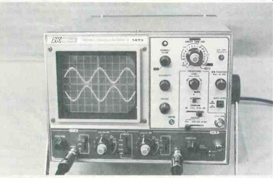
---------- B&K-Precision model 1479 is a new wide-band oscilloscope
with many features making it an indispensable instrument for all types
of service work.
CRT features
Bright blue P31 phosphor with post-deflection of 4kV produces sharp traces of high brightness on the 5.1-inch CRT. The external graticule has standard 8 x 10 centimeter squares plus smaller calibrations on the two center lines (Figure 1). A control on the on/off switch adjusts brightness of the graticule lines. The usual intensity and focus controls are provided along with a screwdriver-slotted astigmatic control that improves the focus at the edges.
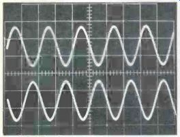
Figure 1--The graticule has full-size 8cmX10cm calibrations. Here is
a typical waveform and graticule when the illumination is adjusted for
maximum.
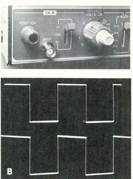
Figure 2--(A) Each channel has a lever-type ac/dc coupling switch that
is convenient to operate. (B) Square waves of 20Hz had no tilt during
dc-coupling operation. With the low-capacitance probe and ac coupling,
the tilt at 20Hz is barely noticeable (bottom trace, indicating good
low frequency response.
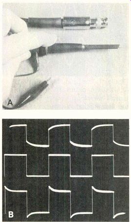
Figure 3---Two good-quality probes are supplied with the 1479 scope.
A change from X1 to X10 attenuation is accomplished by removing part
of the probe, rotating it 180° and reinstalling.
The amount of attenuation is shown in a window. Better frequency response and easier adjustments were obtained by placing the trimmer at the scope connector. The trimmer screw is adjusted through a hole in a metal sleeve of the BNC connector (picture A). At each probe, the connecting hook is exposed when spring-loaded insulation is pulled back. (B) These waveforms illustrate right and wrong probe adjustments. Top trace shows insufficient compensation that reduces high frequencies; the center trace is correct, with tops and bottoms in straight lines; while the bottom trace shows over-peaking.
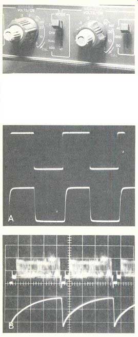
Figure 4--Six types of dual-trace operation can be selected by this
mode switch and other control settings. (A) Top trace shows 20kHz square
waves, with 200kHz square waves below. The 20kHz waveform was very good,
and it included the leading edge. However, the CRT mask obscured part
of the first positive peak. The 200kHz square waves show some rounding
(caused by the generator, not the scope), and the first leading edge
can be seen. Signal-delay lines in both vertical channels allow those
leading edges to be visible. This is important with pulses. (B) Dual-trace
waveforms were sharp, bright and stable.
Vertical
Response is rated from dc to 30MHz (at -3dB) with a rise time of 11.7nS for both vertical channels.
Ten ranges (Figure 2) cover 5mV/ cm to 5V/cm plus a variable uncalibrated control. With an X10 probe, the deflection is 50mV/cm to 50V/cm (or 400V for full height).
Each channel has a lever-type switch located between the volts/cm switch and the positioning control to provide a choice of ac or de coupling to the input signal. The center "gnd" position disconnects the input signal and grounds the input to the vertical amplifier, thus preventing feedthrough from stray capacitance. These lever switches are more convenient to use than slide switches.
A signal-delay line is included in each vertical channel. Without these delay lines, the beginning edge of fast-rising pulses or square waves would be missing. Only high performance lab scopes have this feature.
A 1000Hz square wave is provided at the calibrate jack for probe adjustments. (Two probes are furnished.) Remember, only 10:1 low-capacitance functions need adjustments. Do not adjust when the direct probe input is used. The trimmer capacitor is located at the scope end of the cable, as shown in Figure 3. Connect each probe in turn to the calibrate jack and adjust the trimmer for flat tops and bottoms on the square waves. The probe has an insulated hook for safe, convenient and dependable connections to the circuits under test.
Six functions are made possible by the mode switch (Figure 4).
Either channel can be selected by the ch B or ch A positions. The dual position connects both channels.
For sweep times of 1mS/cm or slower, chopped mode at 200kHz is provided. Higher sweeps automatically switch the operation to alternate. The add position adds signals of both channels together into one trace. However, channel B has a polarity switch for normal or inverted phase, and when the inverted mode is selected, the add function becomes a subtraction where the single trace shows only the difference.
X-Y operation
For vector phase of Lissajous figure operation, the sweep/time switch is rotated fully clockwise to the ch B position. Channel A continues to operate as before, but the horizontal sweep is driven by the signal coming through channel B.
This type of X-Y operation is far superior to the old method of feeding an external signal direct to the horizontal-sweep amplifiers.
The volts/cm switch, variable gain and positioning operate as before with correct calibration (except for the channel B positioning control which now moves the trace horizon tally.) There is one minor limitation: Since the same horizontal-amplifier stages handle the new channel B deflection, the frequency response extends only to 2MHz at -3dB. But that response is much better than the 200kHz of earlier circuits.
Horizontal sweep times
A wide-band scope should have an equally wide selection of sweep times, and the model 1479 B&K Precision does. It provides from 0.5 S/cm (taking 5 seconds for one trace) to 0.20/cm (see Figure 5).
When the 5X magnifier switch is pulled out, the waveform becomes five-times wider, and this provides the equivalent of 0.044 (or 40nS/ cm) fast sweep.
Triggering (locking)
As explained previously in other scope articles, the locking of a triggered scope actually is produced by triggering at the same point of a waveform. When the vertical wave form reaches the level selected by the triggering controls, the horizontal deflection begins. It sweeps from left to right across the screen and shows whatever waveform is there during that time. The beam re traces to the left, but the deflection then is stopped until triggered again by the same voltage level in the vertical waveform.
Basic triggered scopes show a horizontal trace when properly triggered, but no waveform or horizontal line when not triggered correctly. Many of the newer scopes provide a way for the horizontal trace to be seen even when it is not locked. Model 1479 has two such options.
The triggering level control can be rotated to start the trace at the desired point on either the positive or negative peak of the vertical signal. No trace is seen unless a vertical signal is present and the sweep is triggered correctly. When the knob is pulled out, however, the sweep operates even without a signal or locking.
In addition, an auto level button with normal and automatic positions is provided. At the normal position, triggering is determined by the triggering-level control, de scribed before. When the button is pushed in to the auto position, triggering occurs at the average-voltage point of the vertical waveform (see Figure 5B).
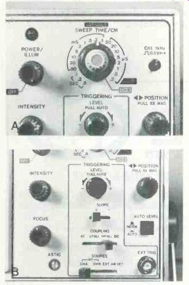
Figure 5 (A)--The sweep-time switch selected horizontal trace times from
0.5S/cm to 0.2/S/cm. A concentric control permits the sweep times to
be reduced gradually. For correct calibration, this variable knob must
be turned completely clockwise. Pulling out the horizontal-position knob
widens the sweep five times, thus giving the effect of one-fifth sweep
time. (B) All triggering controls are inside this area which has a line
around it. One unusual feature is the AM detector (AM DET) position of
the source switch. This permits a stable display of any modulated RF
carrier by locking to the audio that's recovered from this same signal.
Sync controls
Other controls are needed to select the source of triggering sync, to provide the best polarity, and to give any desired sync filtering.
Polarity is selected by the slope switch. Some waveforms lock better with one polarity than the other.
With some waveforms, the horizontal position moves slightly according to the polarity selected.
A source switch is located near the bottom of the triggering section.
It selects triggering sync from these sources: either vertical channel; a signal from the external-triggering jack; or from the AM detector that is provided internally for locking to the modulation of an RF carrier.
Few scopes have an AM detector for the sync, but it is a valuable feature for observing the modulation of a 27MHz CB radio carrier without the bother of connecting to the radio's audio circuit.
The coupling lever switch gives a choice of ac sync coupling, ac with low frequencies attenuated, ac with high frequencies attenuated, or dc coupling. These options produce better locking with some problem signals.
Incidentally, the 1479 is said to trigger on signals up to 50MHz.
Comments
Two physical features of the 1479 should be mentioned with approval.
Four slotted plastic pieces are fastened to corners of the back panel. These are grooved so the power cable can be coiled there securely when the scope is not in use. Also, they serve as feet when the instrument is placed with the scope screen facing up, for storage or carrying.
The carrying handle has finger grooves, and it functions also as a tilt stand. Both knobs are pressed toward the scope cabinet to release the tilt stand, which then can be moved to the desired position. After the knobs are released, the tilt stand locks in that position.
Addition or subtraction of the two vertical waveforms into one trace is a feature that can be very valuable for certain tests. The addition mode allows the summing of two signals without any necessity of floating the scope between two ungrounded points. One example is the showing of true base/emitter waveforms by combining base-to-ground with emitter-to-ground waveforms. Subtraction of two signals can reveal any waveform change (such as distortion) between signal source and the output of an amplifier.
Stability of the model 1479 was outstanding. No drifting of vertical gain, horizontal time or brightness was noticed. Even the horizontal base lines had minimal drifting.
All important power supplies are regulated. This allows full brightness to be achieved without any blooming (any change of trace size upsets calibration accuracy).
In summary, the B&K-Precision model 1479 is a new-generation wide-band scope with excellent performance.
Also see: Reports from the test lab--Nov. 1979
Quick tests of thyristor controls