By Wayne Lemons
Thyristors have become popular as controls for both consumer and industrial electronic gear. A thyristor is the solid-state equivalent of a gas-filled thyratron tube. It even works the same. A small gating voltage turns on the thyristor, and it continues to conduct until anode current drops below a certain value.
Best known among thyristor de vices in control circuits are the silicon-controlled rectifier (SCR) and the TRIAC. The latter acts as (and is diagrammed as) two SCRs connected in parallel but facing in opposite directions.

Figure 1---An SCR may be compared to a current-locking relay that stays
on after being activated, then unlatches when the hold-in coil is shorted
out.
Inside an SCR circuit
Internally, an SCR contains four alternating layers of silicon; two N-type and two P-type. An SCR acts much like a regular silicon diode, except it will not conduct at all until a small activating voltage is applied to its gate element.
A positive trigger (gate) voltage allows the diode to conduct in its forward direction. It continues to conduct even when the gate voltage is removed. This action can be compared to a door with a latch; the latch, once released, has no more control over the door's opening and closing until the door is re-latched. To cut off an SCR, forward current through it must be reduced to a low value or zero. At that time the SCR diode again becomes an open circuit and only the gate has control.
SCR action may be compared in some ways to the current-locking relay of Figure 1. Closing switch PB1 energizes the relay through coil L1. With the relay contacts closed, current flows through both the load and coil L2. Magnetism from L2 holds the relay energized, regardless of whether PB1 stays closed or open. To release the relay, load current can be reduced to a low value, or PB2 can be depressed momentarily to short out L2.
Figure 2 shows an SCR in a dc circuit. In this application its function is similar to what Figure 1 depicts. Gate current is so small it can control even a high-current SCR switch through small low-cur rent wiring.
When the dc voltage is first applied, the SCR appears as an open circuit between anode and cathode. The effect is the same as an open switch. Assuming its forward breakover voltage (VBpp) and peak reverse voltage (PRV) ratings are high enough, the SCR remains an open circuit.
However, a small current applied to the gate terminal (by a closed PB1) turns on the SCR. Resistance between anode and cathode becomes very low. In other words, the SCR reacts almost identically to a regular silicon diode. Since the cathode-anode junction is forward-biased by the dc power source, current flows through the SCR to the load. Once this occurs, the load current "holds" the SCR in conduction. Any change in gate voltage or current now has no effect.
To stop the flow, current through the SCR must somehow be reduced to a point where there is not enough anode current to hold the SCR on. A temporary short from anode to cathode, such as with a pushbutton, will unlatch the SCR. It resumes being an open switch.
Transistor regenerative switch
The latching feature of an SCR results from internal structuring of N and P silicon layers. In some industrial controls, transistors are connected as latches or regenerative switches. Internal workings of such circuits resemble those in SCR switches.
Figure 3 illustrates one simple regenerative switch. Q1 is an NPN transistor; Q2, a PNP. This stage can control considerable power if a suitable high-current transistor is chosen for Q2. Q1 needs only to be large enough to dissipate current drawn by R3 and R4.
First consider the gate open. No current flows, despite a positive voltage applied to Vcc. This is because bias for Q1 comes from the collector of Q2 through R2. Conversely, bias for Q2 develops in the collector circuit of Q1. With neither transistor conducting, neither one has bias.
However, a positive voltage applied to the gate terminal, even momentarily, initiates current flow in Q1. Emitter-collector current in Q1 flows through the emitter-base junction of Q2. This bias starts current flowing in Q2. With Q2 biased on, current starts flowing through the load. Positive voltage at the collector of Q2 feeds through R2 to the base of Q1. Q1 conducts even more. Almost instantly, therefore, both Q1 and Q2 saturate, and full Vcc voltage reaches the load.
The gate no longer has control, because positive bias through R2 holds both transistors in saturation. The stage is latched. To unlatch the stage, as with an SCR, current through the bias circuits must be reduced to a point where voltage across the load (at the collector of Q2) is insufficient to keep Q1 biased on (through R2).
Once Q1 stops conducting, bias for Q2 disappears and halts conduction there too. The stage unlatches. The unlatching action can be accomplished by removing or drastically reducing Vcc, or by forcing either transistor to zero bias-for example with a momentary pushbutton be tween base and emitter.
Unlike an SCR, this regenerative switch may also be turned off by a negative gate pulse sufficient to cut off Q1 momentarily. This negative pulse, however, must be of considerably larger amplitude than the positive pulse on the gate required for latching.
Another interesting facet of this switch is that it may be gated on by a momentary short across either Q1 or Q2 (collector-to-emitter). Also, because of its gain, the stage triggers easily, even by a mere touch at the gate terminal. To prevent erratic triggering, gate impedance must be kept as low as possible. Some designers shunt a resistor (RS) between gate and common; and, if only dc control is expected, a designer may add a capacitor to common from the base of Q1.
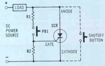
Figure 2 SCR in a dc circuit does not conduct until gate voltage turns
it on, despite forward cathode-anode bias.
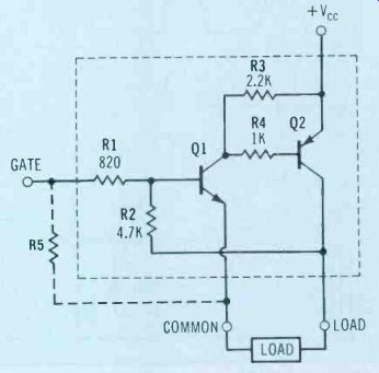
Figure 3 A transistor regenerative switch bears many similarities to
an SCR.
Resistors' values are typical for Vcc of 6V to 12V.
How an SCR handles ac
Dc voltage drop across a conducting SCR typically measures less than 1V. But an SCR behaves as a diode with ac, even when fully turned on. It conducts only on forward half cycles, the same as a regular silicon diode (Figure 4). If the device or load to be controlled operates satisfactorily from pulsed dc, variable control (motor speed, lamp brightness) can be accomplished as well as on-off action.
Consider speed control of a dc motor, for example. When ac is applied to the SCR, it automatically unlatches 60 times per second because of the reversing polarity. If the gate pulse is also derived from the ac line, the SCR can be triggered on only during a portion of each power cycle. This reduces the effective power supplied to the load. In the case of a motor, limiting the average power reduces the speed. If a lamp is the load, lowering power dims the lamp.
Figure 5A shows a simple method of securing gate control from the ac power line. With small values of R, the gate turns the SCR fully on and the SCR operates as a simple rectifier (waveform 1). As R is increased, the gate receives less current, so the SCR does not turn on at the beginning of the cycle, but later. Hence the SCR only conducts current during a portion of the half-cycle (waveform 2). Less than half of the applied ac power reaches the load.

Figure 4---An SCR that is gated on steadily produces the same output
waveform from ac as a regular silicon diode.
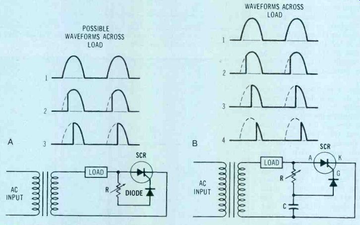
Figure 5---(A) An SCR that's gated by ac controls power to load. Waveform
1 is half-cycle, 2 is less than half-cycle, 3 is quarter-cycle of applied
current. This circuit is limited to a control range between 1/2 and 1/4
(90°) of cycle. In B, adding a capacitor allows control over the entire
half-cycle (180 degr).
As R is increased further, a point occurs where the gate turns on only at the very peak (90° point) of each ac cycle, and only the remaining quarter-cycle reaches the load (waveform 3). Increasing the resistance beyond this point leaves the SCR turned off. Unless the gate receives sufficient current to turn on at the peak, it simply stays off during the downward slope of the sine wave. So no current at all goes to the load.
In some circuits 90° of control may be useful or even desirable.
But for most operations, 180° of control works better. Fortunately, reasonably good 180° control can be obtained with rather simple circuitry.
Figure 5B shows a single capacitor added. Essentially, the capacitor takes a certain time to charge through R. Gate current is delayed by the time constant of R and C.
Triggering takes place later in the half-cycle, since at a particular setting of R the gate capacitor will not have charged sufficiently to trigger the gate until sometime after the downward slope of the sine wave has reached the anode of the SCR (waveform 4). Thus the SCR may be triggered on during only a tiny portion of the cycle.
This delivers smooth control from an entire half-cycle all the way to virtually zero. Hence the term 180° control.
The diode in the gating circuit prevents negative pulses from reaching the gate. A high enough negative pulse could cause break over in the gate-cathode structure, bringing damage or erratic operation. In some SCR controls, a DIAC (discussed later) is used instead.
Sometimes a load is placed at the cathode of an SCR rather than at the anode, as in Figure 6. This provides some feedback control of motor speed. Since a rotating motor develops a certain counter-emf, the speed of the motor creates at the SCR cathode a proportionate bias that must be overcome by the gate trigger voltage. This alters the point on the ac cycle at which the SCR fires. If the motor slows down the counter-emf is less and the SCR fires sooner. The converse occurs if the motor speeds up. The motor-produced bias thus tends to hold the speed stable under varying mechanical loads on the motor shaft.
Resistor R1 and capacitor C2 may be found in SCR or TRIAC circuits controlling an inductive load. Their purpose is to integrate any kickback voltage from the inductance and prevent erratic firing of the SCR. An SCR might also be triggered randomly by transients, especially if the gate impedance is high or if interference spikes are allowed to reach the gate. DIACs or neon lamps often are placed in gate circuits to prevent signals of lower voltage than that of the trigger pulse from reaching the gate.
Many high-power SCRs incorporate an internal ohmic path be tween the gate and cathode, a construction sometimes called shorted emitter. The low impedance thus achieved minimizes any tendency to self-triggering in the high-power circuit.
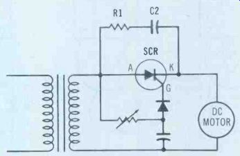
Figure 6---In some speed controls, the motor might be connected in the
cathode circuit of the SCR. R1 and C1 prevent self-triggering of the
SCR due to inductive-load kickbacks.
Figure 7 Use a diode to reveal polarity of voltage coming from the leads of your ohmmeter.
SCR testing
An ohmmeter can help you find most defective SCRs either in or out of the circuit. Common troubles are anode-to-cathode shorts, opens, and-less frequently-failure to trigger or failure to hold once triggered. When testing an SCR, use the Rx1 range of your VOM.
You should be aware of your ohmmeter-lead biasing. Does the red lead of the ohmmeter connect to positive voltage inside the instrument, or to negative? Figure 7 demonstrates how to check your meter. If the main or red probe causes conduction when connected to the anode, the ohmmeter is said to be of forward polarity. If the black or common lead on the diode anode causes conduction, as in Figure 7B, the ohmmeter is reverse polarity.
You also need to know whether your ohmmeter is one of the extremely sensitive ones that uses only 1.5V for the Rx1 ohmmeter scale. That's not enough ohmmeter "power" to check some SCRs.
A small, low wattage SCR generally exhibits diode characteristics between the gate and cathode. That is, an ohmmeter measures high resistance in one direction and low when the ohmmeter leads are reversed. However, this is not true of many larger SCRs. Nearly all of them show between gate and cathode an internal resistance low enough to swamp out any ohm meter other than the resistance itself-typically less than 15 ohm.
No normal SCR should cause any anode-to-cathode reading less than infinity on the Rx1 scale. Ohmmeter polarity should make no difference in the anode-cathode reading.
That is, the SCR should read open unless it is gated.
Here's how to check an SCR for gating (triggering) and its ability to hold. Connect the positive ohmmeter lead to the anode terminal of the SCR, and the negative lead to cathode, as in Figure 8. Momentarily clip a jumper between the anode and gate of the SCR. The ohmmeter (Rx1) should then indicate forward conduction. Once begun, forward conduction should continue, even after the gate jumper is disconnected. To stop conduction, remove one ohmmeter lead from the SCR terminal. Repeat the test.
Figure 8 shows the procedure for both forward- and reverse-polarized ohmmeters. If the SCR triggers on but will not hold when gate is opened, don't conclude immediately that the SCR is faulty. Meter current may not be enough to hold the SCR in conduction. Some larger SCRs may require more than 50mA of holding current, although most will hold with 25mA or less. Small SCRs need only 1mA of current or even less.
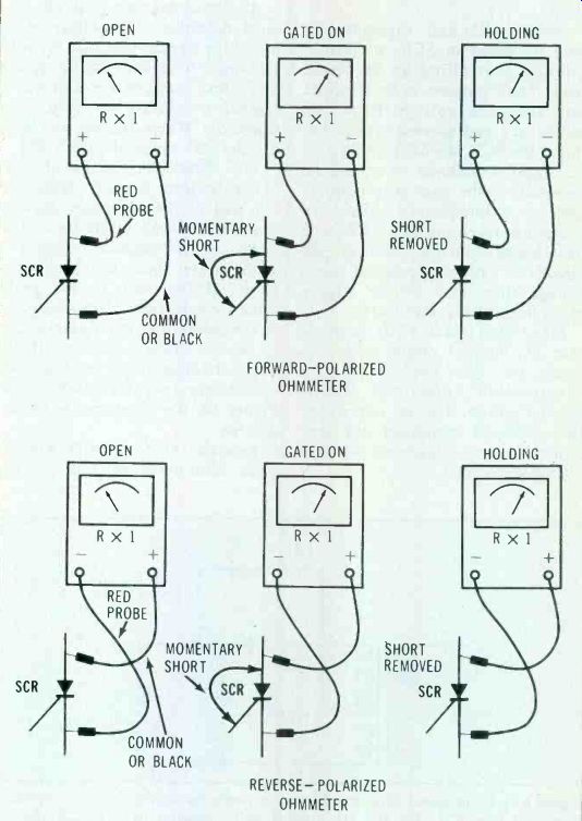
Figure 8---Testing SCR with ohmmeter of either polarity. Clue: Always
gate SCR from anode voltage.
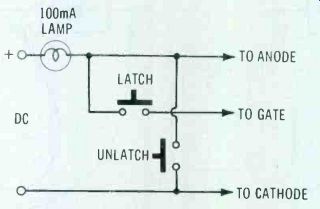
Figure 9---Any supply between 6V and 28V can be used as a test voltage
fo higher-power SCRs, provided the lamp has the same rating and draws
about 100mA.
The simple circuit in Figure 9 illustrates go/no-go testing of larger SCRs that require more hold cur rent than a standard ohmmeter supplies. Any convenient dc above 6V is suitable if you have a matching lamp. The lamp should light to full brightness at 100mA or so. No resistor is needed in the gate circuit since anode voltage drops to less than 1V when the SCR fires. A good SCR should fire upon brief contact at the latch switch. The unlatch button momentarily shorts across the SCR, dropping hold current to zero, which turns off the SCR. The test sequence should be repeated a couple of times.
Infrequently, an SCR tests nor mal on low-voltage dc but performs erratically at regular circuit voltage.
It might even cause fuses or circuit breakers to blow.
This may be due to the forward breakover voltage (VBOO) being exceeded, either because the SCR is defective or because an incorrect replacement has been chosen. At some critical forward voltage, any SCR will self-trigger, even with gate voltage at zero. Any pulse or transient that momentarily exceeds this voltage can fire the SCR.
An SCR can be checked for forward breakover voltage using the method in Figure 10 (or a similar one). For test voltages up to 400V or so, a 10k (5W) series resistor limits the current enough for short-cycle testing. Advance the dc power supply voltage slowly while watching the voltmeter. When the actual VBOO is reached, the SCR should fire and voltmeter reading should drop to near zero.
Also, you can determine the peak reverse voltage (PRV) of the SCR by reversing the SCR leads and repeating the previous sequence.
If power is removed and the do path opened between anode and cathode (perhaps by removing a fuse or disconnecting one end of the load), ohmmeter and low-voltage lamp tests become valid in many SCR circuits. For greater safety, however, disconnect any two leads of the SCR before tests are made-or after in-circuit testing proves inconclusive. Breakover tests should preferably be made with all three leads of the SCR disconnected (in other words, out-of-circuit).
The TRIAC Basically, a TRIAC comprises two SCRs in parallel but hooked in opposite polarity. Figure 11 shows the circuit equivalent and the TRIAC symbol. In fact, if the gate circuits were properly isolated with resistors or diodes, two SCRs could be connected to switch ac power the same as a TRIAC does.
A TRIAC has three terminals, the same as an SCR. But, unlike an SCR, a TRIAC carries no cathode lead to the outside. Instead a TRIAC exposes two anode terminals and a gate terminal. The anodes are labeled Anode 1 and 2 or Main Terminal (MT) 1 or 2.
With an ohmmeter, a TRIAC may at first seem to test the same as an SCR. You find low resistance (but no diode action) between anode 1 and the gate. You should measure high resistance between anode 2 and the gate, and high resistance between the two anodes.
But there's a significant operational difference. A TRIAC, be cause it's designed for full-wave switching of ac, can be triggered (gated) by either a positive or negative pulse. An SCR can be triggered only by a positive voltage.
Figure 12 shows how to test a TRIAC with your ohmmeter. Note that, regardless of meter-lead polarity, trigger for the gate must be taken from anode 2 or main terminal 2. This proves that a TRIAC gate can be triggered with either polarity of voltage.

Figure 10---Testing SCR breakover voltage. For testing reverse breakover,
connect positive lead of supply to SCR cathode and the negative lead
to anode.
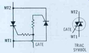
Figure 11---A TRIAC operates like two SCRs in parallel-opposing.
As with SCRs, larger TRIACs might not "hold" when tested with an ohmmeter. The circuit in Figure 9 can be modified to test these TRIACs. Just add a reversing switch, as in Figure 13. Again, any reasonable dc voltage (6V or more) may be used, with a matching lamp.
TRIACs, the same as SCRs, sometimes fail due to a shift in breakover voltage characteristic (or because of an incorrect replacement). Such failures will not show up in low-voltage tests. The break-over tests of Figure 10 work for TRIACs as well as for SCRs. But with TRIACs, the tests should be made both ways; exchange polarities between MT1 and MT2, just to be sure the device triggers in both directions.
TRIACs appear in numerous control circuits for heaters, lights, motors, and even high-horsepower 3-phase motors. They are suitable for any other load requiring on/off or variable power control from a remote point. Figure 14 illustrates a simple motor-control circuit using a TRIAC. Varying the speed-control pot makes the TRIAC switch turn on for all or some portion of a cycle, in the same manner as described for SCRs. But where the SCR controlled only a half-cycle, the TRIAC controls both half-cycles, providing 360° control from zero to full power.
The DIAC in the gate circuit of Figure 14 is a type of thyristor that has no gate of its own. It is designed to break down and con duct upon application of either positive or negative voltage of a certain specified amplitude. Commercial DIACs are available with breakover ratings from about 7V to 30V. Once breakover occurs, the voltage must drop a small amount before current stops flowing.
This compares to a neon lamp, which ordinarily fires at 60V but then remains on until applied voltage drops to around 50V.
Sometimes neon lamps rather than DIACs are put in the gate circuits of TRIACs. In either case, uniformity of triggering is improved.
A DIAC can be checked with a dc voltage and limiting resistor, as in Figure 10. Then reverse the voltage to see that breakover occurs at about the same voltage for both polarities. Or, an ac voltage can be applied and the breakover point monitored on an oscilloscope, as Figure 15 portrays. Whether tested by dc or ac, the breakover point in both positive and negative directions should be within 5% of one another.

Figure 12---After testing a TRIAC with the procedure above, reverse
the ohmmeter leads and perform the same tests again, to check operation
in both polarities. The ohmmeter Rx1 scale must be used, to provide sufficient
holding current.

Figure 13---For checking both TRIACs and SCRs, add a DPDT switch. Test
all TRIACs in both positions.
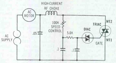
Figure 14---A practical TRIAC-type motor speed control should have a
choke and capacitors to suppress RFI.
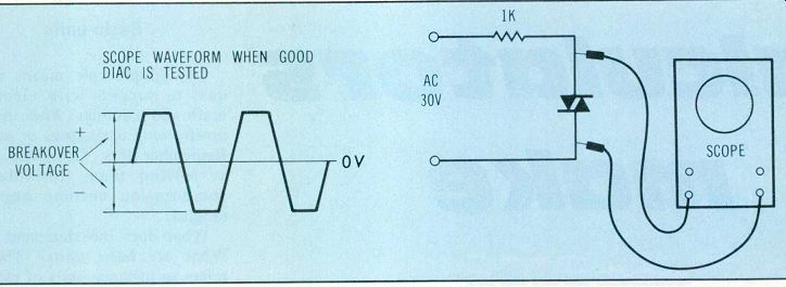
Figure 15---DIAC testing with ac and oscilloscope may not reveal imbalances,
unless dc scope coupling is used.
A shorted DIAC can be spotted with an ohmmeter. But for a suspected open DIAC, a higher dc or ac test is necessary. On rare occasions, premature breakover of a DIAC occurs in either the positive or negative direction. At times this may have little or no effect on circuit operation. In other circuits it may cause a borderline trouble that is difficult to diagnose. A DIAC comes under suspicion when applied power varies erratically at low power settings, or if dial calibration of a controller has changed, or when there are any evidences of nonlinear control operation.
QUADRAC
In a few controller designs, you might find a device called a QUADRAC. This is a TRIAC with the DIAC gate built in. Testing of a QUADRAC requires sufficient gate voltage to overcome the internal DIAC barrier of from 7-V to 28-V or so. Otherwise testing is comparable to TRIAC testing.
Quick tips for testing By and large, intermittent leak age or breakover cause only a small percentage of faults in SCRs, DIACs or TRIACs. This is fortunate, because it makes simple trouble-shooting procedures efficient and usually reliable.
If these direct-control devices check normally, then the trouble is likely in transistor or IC stages that drive the gating circuit. A fault might also exist in the load, or in a power-supply circuit. Sometimes the defect is no more complicated than a dirty potentiometer or rheostat that introduces discontinuities, creates transients, and causes erratic triggering; a new pot is the cure.
Altered resistor values could re duce the trigger point or the pulse itself to some marginal value.
Ordinarily, trigger pulse amplitudes to the gates of SCRs or TRIACs are more than ample. This assures reliable triggering and reduces the switching-time lag. When marginal or erratic operation occurs, a check of gate-pulse amplitude is one of the first tests to make.
RF interference
One side effect of solid-state switching is creation of radio-frequency radiation. An RF choke, often toroidal wound, and a bypass capacitor help minimize this interference. Generally, they are connected as in Figure 14. Shielding and case-grounding also help.
Also see: Reports from the test lab