By Gill Grieshaber, CET
Older color TVs develop different common defects, and thus require modified troubleshooting techniques, from those needed for the same receivers when they were new. These tips should help technicians repair older TVs quicker.
Stresses from heat and voltage cycles that occur over a period of years tend to ruin different types of components than those that usually failed when the color TV was new.
Also, some materials (such as circuit boards, coil forms and tube caps) weaken or disintegrate from heat, humidity and material fatigue.
Older TVs often have multiple defects, compared to the single major failure that's common with new receivers. Also, many minor troubles might have accumulated over the years. These older machines generally require more labor time for adjustments and resoldering, in proportion to the number of new parts installed.
To prevent the total billing from exceeding the TV receiver's value, and to forestall expensive callbacks, it is necessary that a technician work efficiently by knowing fast ways of eliminating all secondary or intermittent problems.
This article provides examples of typical defects and many remedies that are unique to older TV receivers.
Technician damage or neglect A 6-year-old tube-type color TV is likely to have had five to seven repairs or service calls. After that many servicing incidents, several tube shields probably are missing, a couple of coil cores are cracked or frozen, solder splatters are on the chassis, and the convergence coils are in the wrong position.
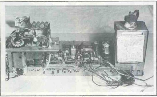
----- An old RCA CTC16 chassis was selected as an example. Notice that the tuner
assembly is mounted correctly on the chassis for servicing or transportation.
Two chassis screws and matching slots in the tuner bracket hold the assembly.
(If the tuner is placed on top of chassis wiring severe damage can occur to
unshielded coils and other fragile components.)
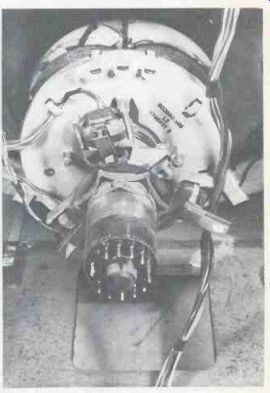
--- The convergence-yoke assembly was crooked on the picture-tube neck,
evidence of previous poor servicing.
The first step, therefore, when checking an old timer is to give it a thorough visual examination. Look for burned resistors and cracked circuit boards, of course, but be alert also for missing parts and other technician-caused problems.
All such deficiencies should be written down for later reference, but they should not necessarily be brought to the owner's attention.
Blaming another technician often gives all technicians a bad name.
Next, all sweep tubes should be tested, since they usually have higher list prices, and the emission and tracking of all three picture tube guns should be checked.
A decision should be made at this time about whether or not to proceed with the repairs. For trade-in sets, the repair cost should not exceed a certain percentage of the proposed selling price. An estimate should be given for all customer merchandise. These are important business decisions, for some old receivers should be junked.
Remove the chassis
The chassis should be removed from the cabinet for the next examinations. It is false economy to attempt these repairs in-cabinet.
Expect to find several bad solder joints. Most of these joints originally were soldered correctly. But the heat of tubes and resistors or heavy heater currents have ruined the solder gradually. Several examples are shown in pictures.
Sometimes a suspected joint shows a crack around the wire lead or rivet when moderate finger pressure is applied to board or component. Resistors that dissipate large amounts of heat often deteriorate the solder at their connecting joints. This is very common when a large resistor is mounted on a circuit board.
Another excellent method is to check all suspected joints by using a reading glass or a low-power microscope. Shine a bright light on the area and move circuit board, resistors and other large components while their soldered joints are observed through the magnifier.
Perhaps many technician readers will reply that looking at each joint is a waste of time, for it's easier to give them all a fast resoldering. Unfortunately, a joint that has become pitted by arcs and has rough grainy solder often will not tin properly. In such cases, the intermittent problem is not solved by casual resoldering, especially when done by an iron with insufficient heat. The only certain method is to tin both parts of the joint separately, solder them with a hot iron and then check the joint with a reading glass.
Circuit boards in older RCA-type chassis often were mounted by soldering board rivets to metal lances of the chassis. As they age, these joints are very likely to become intermittently open. One such open occurs between the metal lance and the rivet. It often can be located by attempting to move the board up and down. But use care, for the lance might be loose inside the solder.
A tiny circular crack is difficult to find when it forms between a rivet and the ground wiring on the board. Flexing the board slightly sometimes widens the crack enough for the open space to be seen. It is imperative for a magnifier to be used here also.
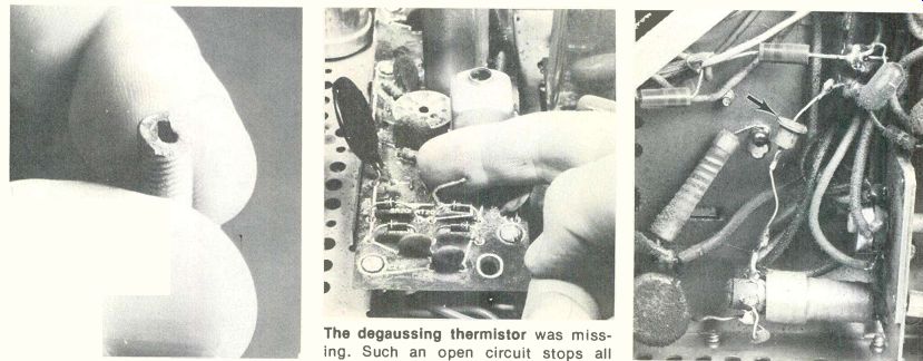
----- This core from a convergence-board coil was cracked at
one end. It still operated alright, but longer lengthwise cracks would prevent
such a coil from tuning properly. A cracked core some times can be removed
with an Allen wrench of the right size. The degaussing
thermistor was missing.
Such an open circuit stops all operation except the tube heaters. For a temporary
test, short across the thermistor leads. The thermistor also functions as
a surge resistor, so it's advisable to replace any bad ones rather than jumpering
them permanently. Another servicing mistake was the conventional top-hat diode
used as a boosted-boost diode. This one was not shorted, but it should have
been, for these are called on to supply about 300V of extra dc voltage-far
above the ratings of the wrong replacement.
Many symptoms from bad grounds Any intermittent open circuit can cause much trouble before it's located, but bad grounds are the worst of all since the symptom and the physical location do not always correspond.
IF circuit boards usually have six or seven separate grounds around the edges. Several might be connected to different ends of the same common ground wiring. Sometimes, a chassis ground is connected to one circuit ground only. An open in such a single-circuit ground is likely to produce a major symptom, such as oscillation or loss of all IF gain.
On the other hand, an intermit tent open at one of the multiple common grounds does not stop all IF operation. Instead, the IF alignment curve shifts, thus causing the color level to change. This can be misinterpreted as a color-IF problem, thereby wasting much valuable time.
Erratic picture quality or color
To find the source of erratic color intensity or varying B&W quality, operate the receiver from a crosshatch/color-bar generator.
Both color and B&W problems can originate in the picture IFs. If the color is affected, tune in color bars.
While watching the color bars on the TV screen, bend the IF circuit board, particularly around the grounds. Check the grounds with a magnifier and resolder all that need it. There is a good probability that repairing the bad grounds will also correct the erratic color level.
Should the erratic continue, gently rock the tubes and IF coils.
Corroded tube sockets are another common source of unstable operation. Spray some good-quality tuner cleaner into all pins of any sockets that are suspected. A little cleaner sprayed on the pins of the tube while it's out of the socket also is a good idea. After the tube is replaced, watch the screen and rock it again.
Many alignment jobs can be made unnecessary by this cleaning and ground-soldering method.
Bad grounds or corroded sockets that produce ringing or oscillation in the luminance signal can be identified and corrected in the same way.
Loss of raster by blooming
One common problem appears as a rapid increase of brightness that soon produces blooming and loss of HV and raster. In the older RCA designs, an intermittent ground at the right rear corner of the chroma board opens the cold side of the-Y amplifier's heater circuit. Of course, the tubes eventually stop conducting, which raises their plate voltages. Because these plate voltages supply the picture tube grids, the brightness is increased severely. This ground location is shown in one of the picture illustrations.
Darker picture
Horizontal-blanker stages in older color receivers were (and are) a constant source of misleading symptoms. In the CTC16 schematic of Figure 1, a large negative voltage is generated by blanker grid current. Part of this negative voltage is used for the killer control, the brightness control, and the 6JE6 horizontal output tube grid. Defects at this grid circuit could affect the picture brightness, the color-killer action, or the lifespan of the 6JE6 tube. Also, the pulse amplitude from the blanker plate plays a large part in determining the picture brightness, since it indirectly establishes the-Y tube plate voltages. Excessive blanker-tube current might burn open the cathode resistor that's shared with the color bandpass tube, thus eliminating all color. This is a busy circuit that can cause many different trouble symptoms.
An intermittent ground at grid resistor R742 increases the negative voltage there and darkens the picture by way of the brightness control.
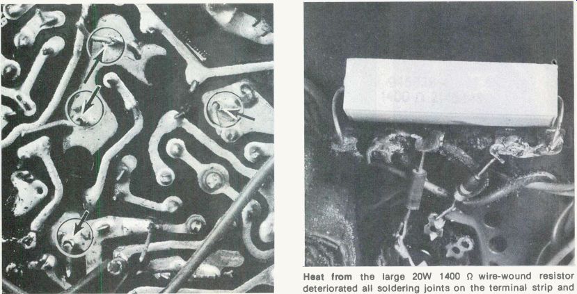
--------- More than eight bad solder joints were found. This closeup
picture has arrows added to mark four joints ruined by resistor heat. These
resistor leads were loose in the solder. Heat from the large 20W 1400 0 wire-wound
resistor deteriorated all soldering joints on the terminal strip and carbonized
the insulation. None of the joints were open, but would have gotten worse
with time.
Flashing horizontal bars
Erratic white and black horizontal bars can appear on any or all high-band (channels 7 through 13) channels if the neutralization of the RF amplifier tube is wrong. The adjustment is stable if it's left alone, but excess tuner spray that gets inside the trimmer capacitor can give the effect of a wrong adjustment.
Adjusting efficiency and HV
If the high voltage is adjusted too low by excessive 6BK4 current, the 6BK4 will fail often. If the HV and efficiency adjustments are wrong, the 6JE6 horizontal-output tube will fail excessively.
Clearly, dependable operation requires that both adjustments be made correctly. However, these two adjustments affect each other, and they should be performed at about the same time.
An additional complication is the small change of 6JE6 plate current that occurs during adjustment of the efficiency coil. Older B&W receivers called this coil "horizontal linearity," and its adjustment made a large change in linearity. Efficiency coils do not change the linearity very much. Instead they are peaked for minimum 6JE6 plate current.
Adapter sockets are available for attaching an external meter to read the 6JE6 cathode current. That method works moderately well.
However, the screen-grid current and the plate current respond in reverse to efficiency-coil adjustments, thus the cathode current changes a smaller amount.
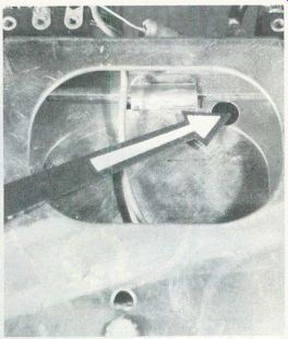
A better method involves monitoring screen-grid voltage during the adjustment (Figure 2A). A decrease of 6JE6 plate current from efficiency-coil adjustment increases the screen-grid current and reduces the screen voltage. (HV current changes affect plate and screen-grid currents alike.) This is a convenient way of monitoring since many RCAs allow measuring of the screen voltage through the space below an elevated 6JE6 socket (see photograph).
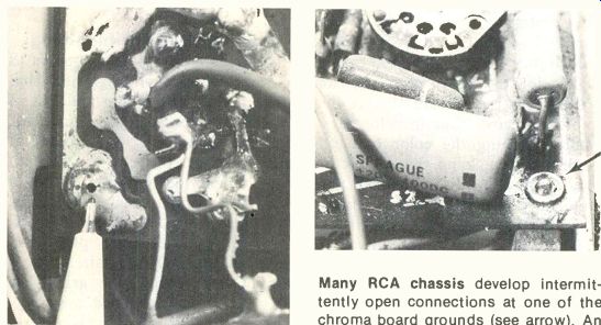
--------- A pen points to the hole in a ground joint of the IF board
where a ground lance had pulled loose. Erratic color level often results from
opens at auxiliary grounds. Many RCA chassis develop intermittently
open connections at one of the chroma board grounds (see arrow). An open produces
extreme brightness and loss of HV. This pictured joint was not bad yet, but
both lead wires of the metal-film resistor in front of it were loose in the
solder.
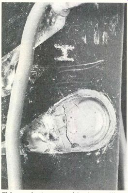
------ This crack at a ground in the oscillator circuit extended
around the rivet completely. It caused intermittent operation of the horizontal
oscillator. Flexing of the board made the crack more visible.
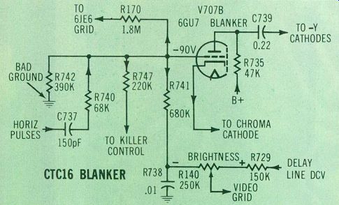
Figure 1---The CTC16 horizontal-blanker circuit can affect the chroma level,
the horizontal-output grid voltage and the picture brightness. Horizontal
pulses at the grid are clipped (by grid rectification) and amplified, then
the plate pulses are applied to the common cathodes of the-Y amplifiers to
produce horizontal blanking. Also, switch-selected variations of the plate
pulse amplitude are used to determine the CRT grid dc voltages. Other pulses
from the cathode are transferred to the bandpass color amplifier where the
burst is gated out. Dc voltage developed by grid/cathode shunt rectification
of the grid pulses is fed to other circuits, such as the color killer, one
end of the brightness control and the horizontal-output grid. Wrong voltages
and pulse levels can cause many different symptoms.
Unfortunately, efficiency adjustments vary the amount of 6BK4 HV regulator current, and the amount of regulator current affects the optimum efficiency setting.
To minimize the number of alternate regulator and efficiency adjustments, the following procedure was developed:
Connect a dc voltmeter across the 1000 6BK4 cathode resistor (remembering that both ends are about 400V above ground).
With a black raster, adjust the HV control for the maximum regulator current recommended for that model (see Figure 2B). Remember, 1V on the meter represents 1mA of regulator current. Old CTC12 to CTC15 chassis should be limited to about 1mA, while newer models (such as CTC31 or CTC38) can stand 1.6mA. Models without adjustable controls can be tested but not adjusted.
While the meter is still connected, advance the brightness control slowly until the regulator current barely reaches zero (use color bars for a stable reading).
Now, adjust the efficiency-coil core for minimum dc volts at the screen grid.
That's all. However, it is advisable to repeat the procedure one more time.
The amount of screen voltage can give definite hints about where a sweep defect is located. For the CTC16, a screen voltage of about +80V indicates the 6JE6 has no dc plate voltage. At the other extreme, if the tube does not have red plate but the sweep is narrow and the HV is low, a screen voltage of +200V or more indicates a weak 6JE6 tube.' Other screen voltages point to different bad parts or adjustments.
Judging brightness
Picture tubes in older model color TVs never (even when new) had as much brightness as new models do now. Therefore, it is difficult to know when maximum brightness has been reached.
With TVs that have a 6BK4-type of HV regulator and a 1000 c cathode resistor, an easy test will prove when the brightness is maximum. Monitor the voltage drop across the resistor and increase the brightness until the voltage barely reaches zero (or slightly above, just to be certain). That is the point of maximum brightness because any increase will cause blooming and reduced HV.
If the voltage drop stops at a higher point even when the control can be rotated further, the picture tube is definitely weak. If the voltage reading does not drop to zero (although the brightness control has reached the end of travel), then the raster gray scale needs to be re-tracked at higher screen-control settings.
Corroded switches
The picture-tube bias and service/normal switches are the cause of many elusive problems. Because they are so seldomly used, corrosion builds up rapidly.
In CTC16 versions, the picture-tube bias switch selects one of three possible values of plate resistance for the blanker tube. With pulses, a lower-value plate resistor increases the pulse amplitude which in this case causes increased grid/cathode clamping at the-Y amplifier tubes.
Increased clamping in turn raises the negative grid bias, thus increasing the plate voltage of each-Y amplifier. The higher plate voltages raise the picture-tube grid voltages and in turn produce higher picture brightness.
-------- Many of the older tuners with Nuvistor RF amplifiers by now
have had tuner cleaners sprayed accidentally into the neutralization trimmers.
This gives the effect of wrong neutralization and produces oscillation on
some high-band channels. The trimmers must be thoroughly cleaned out with
a solvent and allowed to dry before they are adjusted.
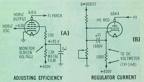
Figure 2---Efficiency-coil and HV-regulator adjustments are easy and accurate
when made by this method. First, find the point of maximum brightness (preferably
on color bars) by monitoring the voltage drop across the 1000 ohm 6BK4 cathode
resistor (schematic B) and increasing the brightness until the resistor voltage
barely reaches zero. Then go through the procedure listed in the text. Adjust
the efficiency coil for minimum 6JE6 screen voltage (schematic A). Finally,
turn down the brightness to a black raster and adjust the HV control for
the proper maximum voltage across the 6BK4 cathode resistor. That's all.
This method works well with similar circuits as long as the output screen
has a large dropping resistor.
Therefore, any intermittent continuity inside the bias switch produces erratic brightness. And a Older TVs steady open usually darkens the picture.
Even worse are the symptoms of a defective service/normal switch.
This switch seldom is suspected of any problem, but corroded contacts that open a circuit can kill the raster and prevent the video from reaching the picture-tube cathodes.
Video and vertical-sweep signals both connect to the switch; there fore, internal leakage can reduce the height or add vertical to the video thus causing a shaded raster.
If any doubt exists about the service/normal switch, remove the wire that connects to the vertical-output grid and then connect together the three ungrounded switch lugs. Any improvement of performance indicates a bad switch.
Temporary cures sometimes can be obtained by spraying a lot of tuner spray inside the bad switch and then sliding it back and forth several times. This trick also works at times with erratic volume or hold controls.
Beware of printed components
The failure rate of capristors (combined capacitors and resistors) seems to be much higher than that of discrete components. In fact, it's recommended that any capristor used as vertical-sync integrator or filter network in vertical-sweep systems should be replaced by the equivalent individual components. Many schematics show the values.
Raspy sound
Distorted or raspy audio tone quality can originate either in the speaker, the FM discriminator or the audio amplifier. Bad speakers are common in old TVs. Most speaker defects can be identified easily. For example, a flapping or buzzing sound that occurs only at loud volume might be caused by an unglued rim, a child's toy lodged against the cone, or a nearby loose object that vibrates in sympathy with cone movement.
On the other hand, if the sound quality is fair when the volume is loud but becomes progressively worse as the volume is reduced, it's a good bet the voice coil is rubbing against the magnet's pole piece.
Gentle pressing of a finger against one point after another around the rear of the cone sometimes will minimize the raspy sound. This identifies the problem, which is not that easy to correct perfectly. A cheap "cure" is to stuff a wadded paper handkerchief between the frame and cone. However, the only permanent solution is to replace either the cone or the speaker.
Open electrolytics
Problems of open electrolytic capacitors should be easily solved now by one of the new generation of capacitor testers. Digital-readout highly-accurate capacitance meters are available from B&K-Precision (model 820), Data Precision (model 938) and Sencore (model CA-55 and model LC-53). Also, the ESR meter from Creative Electronics does not measure capacitance directly but instead checks the equivalent-series resistance. This is sufficient for electrolytics, and the ESR meter can test almost all electrolytics in-circuit without the necessity of disconnecting any leads.
In the absence of one of these meters, there's the clue of white powder around the terminals or else a shunting test.
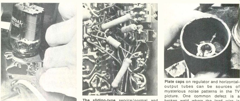
------ The
6JE6 or 6LQ6 screen grid often can be
reached for voltage tests through the ventilation space below the tube-socket
shelf. The sliding-type service/normal and picture-tube-bias
switches often produce baffling symptoms, such as a shaded picture, erratic
brightness or insufficient height. Plate caps on regulator
and horizontal-output tubes can be sources of mysterious noise patterns in
the TV picture. One common defect is a broken weld where the lead wire is
fastened to the metal cap. Such a cap should be replaced since the high heat
would melt solder. This 6BK4 cap was crumbling but the weld was alright.
Comments
Hundreds of "fixes" are known for the older color TV receivers, so seldom should any one repair require an excessive amount of technician time. In fact, servicing the older models should be profitable even when several problems are encountered.
Readers are invited to write to the editor if they would like more tips of this kind or if a certain circuit puzzles them.
Write to:
Carl Babcoke, Editor Electronic Servicing P.O. Box 12901 Overland Park, Kansas 66212 USA.
Also see: Link |