By Ron C. Johnson, C.E.T.
Well, here we are again in this land of great potential, charging upwards, full power. Though significant currents continue to oppose our forces I remain steadfast in my resistance to their rise. In fact, I charge you...
Sorry. Just practicing my speech for the Electronics Club electrons, I mean elections, next week.
Where were we? Ah, yes! Last issue we learned about Scientific Notation, Engineering Units, and the resistor color code before we looked at series and parallel circuits.
This time we'll put series and parallel together as well as looking at some practical aspects of meters, how they work and how to use them.
Alright then! Let's get series, I mean serious.
SERIES AND PARALLEL
Up to this point we have been learning about the very basic concepts of electricity and how we deal with the quantities involved. As we get into series-parallel networks we are finally talking about some practical aspects of the field, We can actually apply some of this stuff to real life situations. Here is an example. Those of you who have an interest in stereo equipment have probably run into the situation where a number of speakers were to be connected together to one power amp output. The power amp specs say that the amp is rated to drive into eight ohms. How should the speakers be connected to provide the correct load to the amp? This is an important consideration, (often ignored), and the consequences of doing it wrong range from inefficient operation, to distortion, to outright damage to the amp.
We don't worry about the technical reasons why it is so critical to keep the load resistance close to the specified value, our job is make sure it is done.
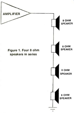
Figure 1. Four 8 ohm speakers in series.
Let's assume that the available speakers are all eight ohms and that we have four of them to connect.
Obviously, one of them connected to the amp by itself would be easy. To connect four is a little more complex. Connected all in series, (Figure 1), they would be additive as we saw in the last issue's segment. The total resistance would be:
80+80+80+80=320
This is obviously too much.
On the other hand, if they were all connected in parallel (Figure 2) the equivalent resistance seen by the amplifier would be: Adding conductances in parallel GT=1/RT=1/80+1/80+1/80+1/80=-4/80=.5 Siemens or RT = 20
And this is much too low.
Now let's mix the two up. In Figure3 we see a series-parallel combination where the two speakers in series are connected in parallel with two other speakers in series. Each brand of two speakers will have:
80+80=160
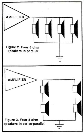
Figure 2. Four 8 ohm speakers in parallel
If we redraw the diagram substituting the equivalent 160 resistances we now have them in parallel (Figure 4). Combining them we get
Again adding conductances GT = 1/RT = 1/160 + 1/160 = .125 Siemens and RT=80
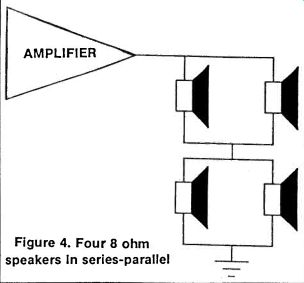
Figure 4. Four 8 ohm speakers In series-parallel.
The same could be accomplished by configuring the speakers as in Figure 5 where two sets of 80 speakers in parallel are connected in series. Each parallel set has an equivalent resistance of 40. When the two equivalents are added together we get 80.
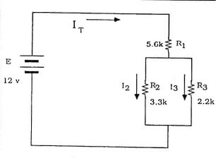
Figure 5. A basic series-parallel circuit
SOME THEORY
So series-parallel networks can be useful and, in fact, most practical circuits have complex combinations of series and parallel branches. Quite often we need to be able to analyze these networks so we can predict the voltages across components, currents through them, power dissipated in specific devices or the equivalent resistance of a combination of components.
And most of it can be done with the help of our old friends, Ohm and Kirchoff.
Figure 5 shows a basic series-parallel circuit with a DC voltage source. The total current flowing out of the voltage source is IT. All of this current flows through R1. It then splits and some flows down through R2 and some through R3. We will call these currents I1 and I2 respectively.
The sixty-four thousand dollar question is: How much will flow through each resistor? Also, how do we calculate RT, IT, the power dissipated in each resistor... Okay, so it's more than one question. What is the approach?
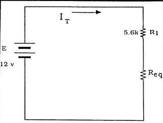
Figure 6. The parallel combination replaced by an equivalent resistance.
Usually the first step is to find the total resistance in the circuit the total load presented to the power source. This will allow us to determine the total current flowing in the circuit. The trick is to combine the resistances in the correct order. Any time the current in the circuit splits we must have a parallel section in the circuit. In this case it is R2 and R3. We can't combine R, with them until we know their equivalent resistance. So we either add their conductances and then convert back to resistance or we can use the "product over sum" rule described in the Rules and Formula section. Once we have an equivalent resistance we can redraw the circuit (Figure 6) with the R2-R3 combination as a single resistor and place it in series with R1. From there we simply add the two resistances together to get RT. Try this example. It's easy and it will help you get comfortable with the procedure. Again referring to Figures let's make R, a5.6 k ohmresistor, R2 a3.3k ohm and R3 a2.2k ohm. (These are all standard EIA resistor values so you could set this up and confirm that it works.) The voltage source is a 12 volt battery but practically any low voltage DC source would do for experimentation. We said we would have to determine the equivalent resistance of the parallel branch first.
Using the "product over sum" rule we get
Req 3.3 k-O X 2.2 k-O = 1.32 k-Ohm 3.3k-O+ 2.2k-Ohm
We then put the Req in series with R, and add them together.
RT = R, + R eq = 5.6 k-O + 1.321(0 = 6.92 k-O
We could now redraw this again as a simple series circuit: a voltage source, one resistance and a current carrying path. But let's just calculate the total current flowing out of the voltage source:
IT= E/ RT= 12v/6.921(0= 1.73 mAmps
So now we know the source voltage, the total resistance in the circuit and the total current drawn from the supply. The purpose of our analysis will determine where we go from here. We could find the total power dissipated in the circuit using P = IT X E and the information we have so far. Quite often though we want to know how the current splits through R2 and R3. There are a couple of ways of finding this. We know one way using the tools we already have. You can check out the Rules and Formulas section for another way called current divider rule.
Take a look at Figure 6, again, where we have redrawn the circuit diagram showing the R2-R3 parallel combination as an equivalent resistance. We have seen this circuit before and know how to find the voltage across Req. VReq would be equal to Req times the current through it since Req is the equivalent resistance of the parallel section and IT flows into that combination.
If VReq is across Req then that same voltage is across the parallel combination of R2 and R3 which means that each resistor has the same voltage, VRec across it.
To determine the current through either one of those resistors we just use Ohm's Law: IR2-VReq / R2 and IR3 = VR., / R1
These two values of current should add up to IT which was calculated before. (Just for practice, go ahead and calculate these currents and check). All of this brings up some rules which, while they are not absolutely necessary to know, can be useful in this process of circuit analysis.
I know, more rules and formulas, but they are pretty simple and can help streamline your analysis technique.
KCL No, this doesn't stand for Kentucky Cooked Lizard.
Actually Kirchoff had two good ideas. Kirchoff's Current Law states that the algebraic sum of all the currents entering and leaving a node will equal zero.
What this really means is: "what goes in has to come out." A node is an electrical connection of two or more components. If current flows in from one branch the same amount has to flow out somewhere. In our previous example the current, IT flowed into Node A, where R1 connects to R2 and R3. The same amount of current-the total of 12 and 13-must equal IT. Another way of calculating how much flows in each branch (Current Divider Rule) is shown in the Rules and Formulas section along with a method of finding the voltage across a resistor in a series circuit (Voltage Divider Rule). METERS Probably most of you have had an opportunity to use a meter at one time or another. Perhaps you have one of your own. Our purpose here is not to cover the use of meters as much as to talk about how meters relate to this subject of series-parallel circuits. Even so, we'll take a general look at meters as a way of introduction.
We could categorize meters in several ways. We could differentiate between, analog and digital meters, bench meters and portables, specialty meters versus general purpose, or high accuracy versus economy units.
For our purposes let's talk about functions. The basic meter we are considering measures voltage, current and resistance, the quantities we have been dealing with in this series. In addition to DC values most meters of this type will measure alternating currents and voltages. Older units were called VOM's (Volt Ohm Meter) while others were TVM's (Transistorized Volt Meters), VTVM's (Vacuum Tube Voltmeters), and more recently DVM's (Digital Voltmeters). In all cases, though, the same quantities were measured. Before the advent of digital technology and the availability of digital displays, bench and portable test meters used various kinds of electromechanical meter movements for indication.
Many were excellent pieces of test equipment considering the delicacy of their meters movements, difficulty of interpreting scales and limited specifications. (More on that later.) Digital meters, which have replaced analog for most applications, have benefited, not just by their solid state displays but also by the improved technology used in their input sections. In addition to being more rugged, generally, they can fit more functions in a smaller package and give better specifications.
We'll take a look at some actual products and their use in another segment.
The important concept that must be understood is that although the equipment available is generally very good, meters do have an effect on the circuit they measure. Figure 7 shows a simple series circuit with two resistors, R1 and R2 and a 20 volt source. Let's imagine that you have been asked to measure the voltage across R2 with the meter shown. If the meter was perfect it could be connected across R2 and it would indicate the voltage dropped there. We could predict what that voltage should be by using voltage divider rule to calculate it.
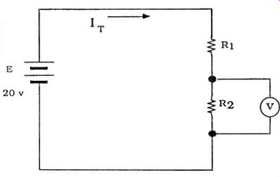
Fig. 7
A perfect or ideal meter would look like an infinite resistance and so would draw zero current from the circuit and consequently have no effect on it.
However, meters are never ideal. Such is life. In reality meters have an internal resistance which, while very high, is a finite value. So in order to use our own meter intelligently we need to know under what conditions it will "load down" the circuit. If it loads down the circuit it will give significantly erroneous readings.
For example, digital meters often have an input resistance specification of over 1 MO which is very high-much higher than most analog VOM's. If R1 and R2 in Figure 7 were 1000 resistors we could calculate VR2 to be 10 volts. If the meter (1 MOhm) were connected across R2 we would have to consider a 1 M-O resistor to have been connected across R2. We would then recalculate VR2 based on an Req of 1000 in parallel with IMO. In this case the change in Req would be negligible.
But what if R, and R2 were 1-MO each? In that case VR2 should still be 10 volts, because the ratio of the resistors is still the same, but now Req would be a 1-MO resistor in parallel with a 1 M0 meter resistance which would equal 500 k-O. Using the voltage divider rule and the equivalent resistance we would get VR2 = (500k-O/1.5M-Ohm) X 20 volts = 6.67volts
So the meter would read 6.67 volts even though it should be reading 10 volts. This is a case where the meter is loading down the circuit. Sometimes this is difficult to avoid but at least being aware of the problem helps to understand why you are getting unexpected readings. This will happen when measuring voltages across high values of resistance.
A similar situation can come up when measuring current. We have been saying that we always talk about the current "through" a component so it makes sense that in order to measure current we have to break into the circuit and route the current through the meter. Ideally the meter, when measuring current, would have zero resistance, thereby contributing nothing to the total circuit resistance. Practically speaking, the resistance of an ammeter is very low, usually just a few ohms. This presents no problems in some cases but, again, there are circumstances where it becomes a problem.
Figure 8 shows a simple series circuit with an ammeter connected in series. The resistance in the circuit is 1 k-O and the power source is a 20-volt supply.
Without the ammeter in the circuit the current would be:
IT=20 v/ 1-kO=20 mA
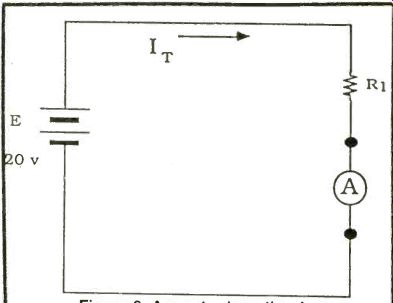
Figure 8. Ammeter insertion loss.
With the ammeter in the circuit we are adding 100 to the total resistance. Ten ohms is small compared to the 1k-Ohm resistor and will make practically no difference to the total current. On the other hand, if the circuit resistance was 200 (which would give a current of 1 amp) adding the ammeter to the circuit would change the total resistance to 300 instead of 200. This would limit the current to 667 mA instead of 1 amp so the meter would be affecting the operation of the circuit.
Again we must be aware that when connecting an ammeter in series with a circuit which has a low total resistance that the meter will affect the circuit noticeably.
Well, that about wraps it up for this issue. Next time we'll talk about ideal and practical DC energy sources before we move on into some basics of Alternating voltage and current.
Hope we didn't load down your circuits.
----------------
UNDERSTANDING ELECTRICITY
SOME USEFUL RULES AND FORMULAS
In last month's segment we talked about how to calculate equivalent resistances. We said that resistances in series are just added together but to determine the equivalent resistance or resistors in parallel the simplest way was to use conductances. So: GT = 1/RT = 1/R, + 1/R2 + . . . 1RN where GT is conductance in Siemens, S, and N is the number of resistors.
This will calculate the equivalent resistance for any number of parallel resistors. But if you have just two resistors in parallel it may be simpler to use what is called the "product over sum" method. (This is just a derivation of the conductance method.)
R, X R2 Req 191 + R2
If you have more than two resistors in parallel, any two can be reduced to an equivalent which can then be combined with the third.
In the case where resistors of the same value are in parallel the value of the resistors divided by the number of resistors will give the equivalent: Req = R/N
Voltage Divider Rule
Kirchoff tells us that around any loop the voltage rises must equal the voltage drops. Last issue we calculated the total resistance in a series loop and found the total current. We then multiplied the value of a particular resistor times the current to find the voltage drop across that resistor.
Voltage divider rule is just a quicker way to do the same thing.
Given a series circuit with two resistors (R1 and R2) we can find the voltage across either one by using the following formula:
VR, E X R,/(R,+R2)
or VR2 E X R2/(R,+R2)
What the formula is saying is that the voltage across the resistor will be proportional to the ratio of that resistor to the total resistance of the circuit.
Current Divider Rule
Current divider rule is used to determine how much current splits down the branches of a parallel circuit and as in VDR it uses a ratio. In this case, however, the current through a resistor in one branch is proportional to the ratio of the resistance of the other branch to the total resistance.
IR1-IT X R2/(Ri+R2)
and IR2 = IT X R1/(R1+R2)
Also see:
UNDERSTANDING ELECTRICITY--PART VII
adapted from: Electronics Handbook 1992