Reading about electronics can be fun and instructive, but the only way to become a knowledgeable technician is to get hands-on experience, by actually connecting resistors and capacitors together in circuits that do something. These circuits can be as simple as turning a light on or off, or making some kind of alarm sound. As long as we have a power source and a load connected together by wires, we have a functioning circuit.
Another way to think about circuits is to consider one part as the input and another part as the output, This is notably true of amplifiers. You will note that the projects in this section usually "do something," that is, they accomplish some useful purpose. With a little experimentation and/or expansion, you may be able to find other uses for these circuits. If you study them and put several combinations together, you will increase your understanding of how all electronic components and circuits work.
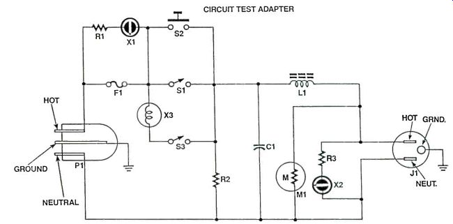
CIRCUIT TEST ADAPTER
When you build a circuit it would be nice to know if it will work before you plug it in to the 110 VAC power.
No matter how careful you may be, there could still be problems. For your protection and also for the protection of the circuit, it would be wise to plug it in to this device first. Another feature of this device is its ability to test shorted equipment. X3 allows about 3/4 Amp of current maximum, and will drive into a dead short without exceeding that current. This allows the troubleshooting of shorted circuits with power on them. When the short is found and cleared, the adapter can be switched to normal power.
Each component used has a specific function.
Fuse (F1) protects from overloads and should be easily accessible so it can be changed to match the instrument under test. Range for F1 is from 1 to 12 amperes.
R1-X1 monitor the fuse and indicate if it blows, with R2 acting as a load to complete the indicator circuit. S1 is the switch for normal power, and S2 is a pushbutton with momentary contacts, to give only a few seconds of power. X3-S3 are used for shorted circuits, or current-limited testing. C1, L1, and M1 function as an RF suppressor and spike suppressor, and L1 limits current changes and sets a high limit on output current. R3-X2 serve to indicate the presence of power on the output.
Construction:
This device should be built in a box large enough to allow air flow around X3, as this bulb runs HOT. Vents above the bulb and at the bottom of the box are appropriate. R1-X1 and R3-X2 could be neon light assemblies, to facilitate construction. R2, C1, L1 and M1 could be mounted on a small PC board or perfboard, or tie strips could be used. X3 should be in a standard Edison socket to allow it to be changed for different output currents:
Always use the bulb that will not allow the circuit to receive too much current:
Using The Adapter
First, plug the adapter into the 110 VAC power. Next, with all switches off, plug in the device to be tested. Then, push S2 on for an instant. If the fuse doesn't blow, try it on longer. If still ok, then switch S1 to on. If the power remains on after that, the device under test is OK.
Should the fuse blow at any time during the test procedure, turn on S3 after the fuse is replaced. Lightbulb X3 will restrict current so you can trace the circuit and find the short.
PARTS LIST: FOR THE CIRCUIT TEST ADAPTER
R1--X1, R3-X2--Neon light assemblies.
R2--100K Ohm, 1/2 watt resistor
C1--0.01 Mfd, 2000 WVDC capacitor
M1--MOV for 110 Volt AC, 80 Joules
S1, 3-SPST switches
S2-Normally open pushbutton
F1--Fuse/fuseholder: Range of 1-12 Amps
P1, J1--110 VAC power plug and receptacle
L1--22 turns #16 wire on 1" diameter core.
Misc: -- Wire, solder, box, socket for X3
----------- CIRCUIT TEST ADAPTER
--------------
BATTERY SAVER ALARM SYSTEM
Most electronic devices draw power even in standby, more power than this circuit. With the alarm in the armed mode, the draw will be in the nano-ampere range! Another big advantage of this circuit is physical size. It can be assembled on a 1"X2" piece of perfboard. Most batteries are as big or bigger than this circuit.
Operating voltage is another benefit of this circuit.
From 5 to 15 volts DC, it functions properly with no change of components. In fact, 01 could be almost any small NPN transistor that will switch on and stay on with an open in the normally closed loop.
Similarly, Q2, the SCR, can be any SCR from 1 Amp up with at least 100 PIV, that will gate in the circuit.
Many 4 and 8 Amp units will work. Even some higher current units will work. Connect a relay, whose coil voltage equals the supply voltage, to the output and you can control whatever you want, even contactors for large motors.
Do not view this as only an alarm circuit. It can be used as a control circuit, with micro-switches or other contacts as sensors and a motor, contactor, relay, etc as the output load. This circuit lends itself to being used as a zone in a multizone system. As each zone draws only a small amount of power, many zones could be used on a small power source. The only limiting factor is horn power requirements.
This circuit is ideal for small self-contained systems for such things as cabinets, tool cases, and luggage.
Several tiny sonalert type buzzers are available for
PARTS LIST FOR THE BATTERY SAVER ALARM
R1--1 Megohm resistor, 1/4 watt
R2, 3, 6--10K Ohm resistor
R4--1K Ohms resistor
R5--100 Ohms resistor
R7--390 Ohms resistor
C1--10 Mfd, 35 WVDC, capacitor
D1--1N4004 Diode
Q1-2N3904 Transistor
Q2-SCR 1 Amp @ 100 PIV minimum X1-LED
--------------------------------
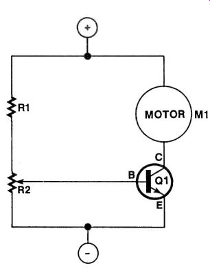
MINI MOTOR CONTROL
Hobby motors and small toy motors are made to run full speed. However, some uses for these motors may involve running them slower. This small circuit will do just that.
A motor that operates from 3 to 12 volts with a current of 2 Amps or less can be controlled by this unit. A heat sink is recommended for Q1 since it will get hot at slow speeds.
The resistor values given are good, but you might want to adjust them for optimum performance with the voltage and the motor of your choice.
Operation of the motor control is simple. R1 and R2 are a voltage divider. R1 limits the power available to R2 so an excess bias can not be applied to Q1. R2 sets the bias on 01, from cutoff to saturation, and should be a linear taper potentiometer.
Q1 controls the motor by increasing the power available to it or decreasing according to its base bias from R2.
Now you can make them fast or slow without wasting power in a big rheostat.
PARTS LIST FOR THE MINI MOTOR CONTROL
R1-330 Ohm 1/2 watt resistor R2-5K Ohm potentiometer
Q1-TIP 3055 Transistor M Motor, see text
------------------------------
HIGH-IMPEDANCE BUFFER
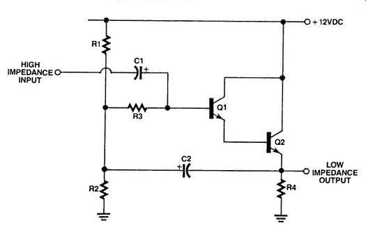
There are times when the signal you want to use has just too much impedance to be hooked up to an ordinary audio amplifier. The signal coming from a crystal radio is one example. This simple circuit is called a "Bootstrapped Darlington Emitter Follower" and has an input impedance of about 20 Megaohms.
With their collectors tied together, transistors Q1 and Q2 form a Darlington transistor with the emitter of Q1 feeding the base of Q2. The total current gain, beta, of the two transistors is now B1 x B2. So if each transistor has a gain of 100, then the total current gain is now 100 x 100 = 10,000. The audio input is fed to the circuit via decoupling capacitor C1. The signal goes straight to the base of transistor Q1 and is immediately processed.
The DC bias is set up through resistors R1 to R3.
The initial voltage at the base of Q1 is set up by the potential divider of R1 and R2, while R3 provides DC isolation. This resistor plays a vitally important role as we shall see in a moment.
The emitter resistor (R4) is the load resistor and the output is taken from here. The output signal is also coupled back to the DC voltage divider.
The circuit has no voltage gain since we are using a current gain configuration i.e. the emitter follower. So, effectively, the same voltage that appears at the base also appears at the emitter.
Now with capacitor (C2) coupling this signal back to the voltage divider, you can see that both sides of resistor R3 have the same AC voltage, i.e. whatever appears from the input also appears at the voltage divider end of R3.
This raises the input impedance of the circuit enormously, to the vale of R4 x the gain of the two transistors. If the beta of the two transistors is 10,000 as above, and we have a value of 100 kilo-ohms for R4, then the input impedance becomes 1,000 Mega-ohms.
However this is theory only. Because of leakage currents through the capacitors and the transistor, this value drops to around 20 Mega-ohms, but this is still much higher than can be obtained through normal transistor circuits.
Construction
The important thing here is to use transistors that have a beta value of at least 100. Also keep the component leads as short as possible otherwise, in some cases, the circuit will pick up radio frequency signals and amplify them as well.
Note that this circuit is not a voltage amplifier but a power amplifier. The circuit produces the same output voltage as the input voltage but the output impedance is much, much lower than the input impedance. i.e. 20M to 10K. So we have amplified the current, rather than voltage.
With this lower output impedance, the signal can then be taken to any ordinary audio amplifier such as your stereo or to an Opamp preamplifier etc.
PARTS LIST FOR THE HIGH-IMPEDANCE BUFFER
C1, C2--4.7uF, 16VW electrolytic capacitors
Q1, Q2--Any small signal NPN transistor with beta = 100 (2N2222 or Equiv.)
R1-R3--100K, 0.25W, 5% resistor
R4-10K, 0.25W, 5% resistor
---------------------------------
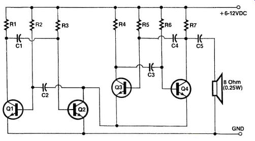
THE ELECTRONIC CRICKET
Every now and then, it's great to have a project that is a little less serious and a lot more fun. This project fits this perfectly. It uses just four transistors and can be put together in only an hour or two.
It can be called the Electronic Cricket or just about anything else you like. As soon as the power is applied, it begins making the repetitive chirp of a cricket.
The project can be made as small as you like. You can then hide it in an inconspicuous spot. The sound carries so that it's difficult to find its location.
Let's take a look at how the circuit works. If you look closely, you can see that it consists of two transistor multivibrators. The first is made up of transistors Q1 and Q2 and the second is made of transistors Q3 and Q4.
The difference here is that the second multivibrator is driven by the first. This can be seen from the fact that the emitters of transistors Q3 and Q4 are switched in and out of circuit by transistor Q2.
Now we'll look at the function of both multivibrators. If we look at the first multivibrator, it has two timing capacitors--a 470uF and a 100uF electrolytic capacitor.
These produce the time delay between chirps so that there appears to be some "dead time" i.e., time where there is no sound at all. This is important to make it sound realistic.
The way this works is that because the two capacitors are different in value, one transistor will switch on longer than the other and the way the circuit is connected, this will be transistor Q1. In fact, it will be on for about 80% of the time. This also means that transistor Q2 will only be on for about 20%. When 02 is on, this switches in the other half of the circuit.
Transistors Q3 and Q4 are set up to make the chirping sound. Again we have two unbalanced timing capacitors--a 4.7uF and a 0.1 uF capacitor.
This Construction
This project is very easy to construct because it doesn't use any "easy-to-blow-up" components. You can put it together using perfboard or the European style VERO-board-whatever you use, the only thing is to make sure you don't use too much solder and make sure every contact is secure.
[...] produces an audio oscillator that has a very narrow duty cycle i.e. the output is "low" for much longer than it is "high," and this sound is very much like that of a cricket chirping away.
The output is taken from the collector of transistor Q4 via a 470uF capacitor to the speaker which can be any 8 ohm type.
Every time transistor Q2 is on, you'll hear the chirp coming from the speaker. And every time you hear a chirp you'll see the two LEDs light up for an added special effect. It looks great in the dark.
The power supply can be anywhere from 6 to 12VDC. The current consumption is very low so you can use penlite cells if you like.
If you have a small case, this would be ideal so that the cricket can be self contained in its own little body.
Now go off and have fun with your insect friend....
PARTS LIST FOR THE ELECTRONIC CRICKET
C1, C5-470uF, 16VW, Electrolytic capacitors
C2-100uF, 16VW Electrolytic capacitor
C3-4.7, 16VW, Electrolytic capacitor
C4-0.1 uF Mylar capacitor
Q1-Q4--B0548 NPN Transistors or 2N2222 or G.P. Silicon
R1, R4, R7-1 K ohm. 0.25W, 5% Resistors
R2, R3, R5, R6-10K ohms, 0.25W, 5% Resistors 18 Ohm, 0.25W Speaker
-----------------
MICROPHONE HUM FILTER
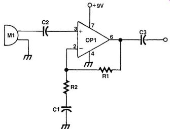
Pre-amplifiers for microphones generally operate at high gain levels in order to boost very small signals. With high gain levels, hum (low frequency 60Hz) pickup can be a problem. For Opamp based circuits, in the non-inverting mode, a solution is to place a capacitor, C1, in the resistor feedback loop as shown. OP1 is shown configured in a standard AC-coupled non-inverting mode. Resistors R1 and R2 are the gain setting components. R2 is normally connected to ground. By adding a capacitor however between R2 and ground, the gain at low frequencies is reduced and hence hum pickup is also reduced. Component values are not critical and can be changed to suit your objectives.
PARTS LIST FOR THE MICROPHONE HUM FILTER
OP1--TL081 low noise Opamp
C1--10Mfd capacitor
C2--0.1Mfd capacitor
C3--0.1 Mfd capacitor
R1--100-K ohm resistor
R2--1-K ohm resistor
M1--crystal microphone
-----------------
TRANSMITTER VERIFIER
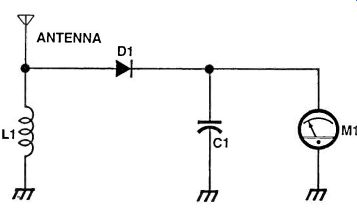
Low power F.M. transmitter circuits for the VHF broadcast band (88-108 MHz) are popular construction articles. The simple circuit shown here checks for the presence of RF emission. The antenna is 12 inches of solid hook-up wire coupled to inductor (L1), which is made by winding 7 turns of close-wound solid hook-up wire over a standard HB pencil, used to give the coil form. Diode (D1) rectifies the signal, which is further enhanced by capacitor (C1). The AC output is displayed on a sensitive 0-20 uA meter. To use, merely place the antenna as close as possible to the tuned circuit of the transmitter.
PARTS LIST FOR THE TRANSMITTER VERIFIER
Ant. 12" solid hook-up wire
C1--0.1 uF Capacitor
D1--Germanium diode, 1N60
L1--Custom inductor (7 turns close-wound solid hook-up wire on pencil former)
M1--0-20 uA DC Meter
+++++++++++++++++++++++
Also see:
adapted from: Electronics Handbook XV (1994)