033 AUTOMATIC CAR ALARM
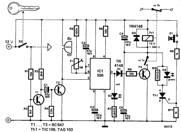
Even the best car alarm is useless if you forget to set it upon leaving your car, whence this circuit.
The relay has a make and a break contact: the former is necessary to delay the switching in of the alarm after you have got out of your car, and the latter serves to switch on the car alarm proper.
Immediately on re-entering your car, you must press the hidden switch, S1. This causes silicon-controlled rectifier Th1 to conduct so that the relay is energized. At the same time, the green LED lights to indicate that the alarm is switched off.
As soon as the ignition is switched off, T1 is off, T2 is on, and the buzzer sounds. At the same time, monostable IC1 is triggered, which causes T3 to conduct and the red LED to light. The silicon controlled rectifier is then off, and D4 is reverse biased, but the relay remains energized via its make contact for a short time, preset by Pt As soon as this time has lapsed, the relay returns to its quiescent state, and the alarm is set via the break contact. The delay time can be set to a maximum of about 1 minute.
---------
034 BICYCLE LIGHTS AND ALARM
A bicycle or tricycle should, as everyone knows, be fitted with front and rear lights. The noteworthy aspect of the lights circuit described here is that it also provides a visible alarm, which is primarily in tended for invalid road users. When such handicapped people are in need of assistance during the day, this is quickly spotted by passers-by. At night, this is, unfortunately, not so, whence the present circuit.
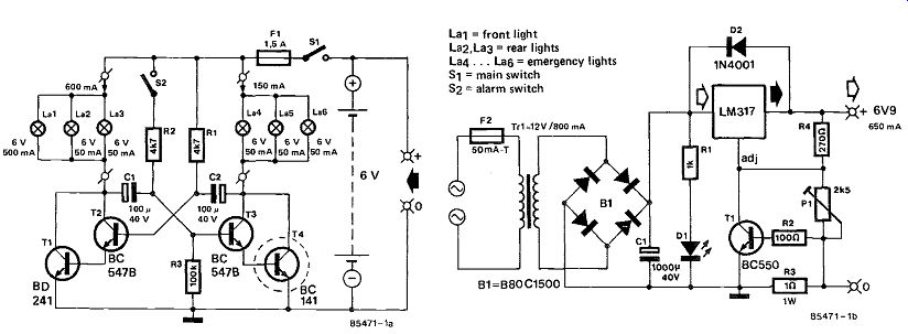
The usual dynamo or battery is replaced by a 6V rechargeable lead-acid battery, which ensures that the bicycle lights are operational even when the bicycle is not moving. When the rider is in need of assistance, the alarm can be switched on: in addition to the normal lights, a small display with the word "HELP" will then flash. Such a signal for help is not easily overlooked! The circuit is based on an astable multivibrator, which does not operate when alarm switch S2 is open. Provided S1 is closed, the front and rear lights are on, however.
When the alarm switch, S2, is closed, the multivibrator operates, which causes the normal lights and the HELP lights to flash alternately.
The circuit is powered by a 6V 1.8 Ah lead-acid battery which, when properly charged, is sufficient to keep the lights on for about three hours.
The circuit can be fitted in a small, preferably water-proof, case. Lamps Lao . . Las light the letters "HELP" that have been cut out in the lid. The BC141 should be fitted onto a small heat sink.
Because of the need of regularly charging the battery, the case should be fitted to the vehicle in a manner which allows easy removal and attachment.
A circuit for a suitable charger is given in figure 1b.
This provides a constant charging voltage of 6.9 V (preset with P1), while the charging current is limited to about 650 mA. This enables the battery to be fully charged in around 3 hours. The charging voltage should be set carefully, otherwise the battery will not be charged correctly.
--------
035 BRAKE LIGHT'S MONITOR
The circuit described below monitors your car's brake lights, and indicates by a light-emitting diode whether they both function correctly. In that sense, it can save you money by preventing your being fined for driving with defective brake lights, and it also leads to increasing road safety.
The monitor depends inevitably on the voltage drop across the supply lines to the two lamps. For the circuit to work correctly, that drop needs to be greater than 0.6 V. If this is not so, the drop must be in creased by adding a 5V diode in series with each lamp. Transistor T1 and T2 in figure 1 form a Schmitt trigger, which reacts to the voltage drop across the supply lines to the two brake lights. This reaction manifests itself in D1 lighting via T3. If one of the brake lights is faulty, the switch-on cur rent drawn by the other lamp will cause D1 to light briefly when the brake pedal is pressed. If both brake lights are defective, D1 will not light at all.
All three possible states of the brake lights are thus indicated.
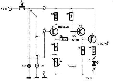
-------- The hysteresis of the trigger, and, therefore, the sensitivity of the circuit, can be adjusted within narrow limits with P1. The preset is best adjusted with one lamp out of action in a manner which makes D1 light briefly as described above.
If you find it disturbing that D1 lights every time you brake, the operation can be reversed by replacing the BC557B in the T3 position by a BC547B (n-p-n). The collector of T3 is then connected to the positive supply line, and the emitter to R6. On the printed circuit board this means that the flat edge of T3 must be turned the other way. A second base connection has also been provided on the PCB.
Note, however, that this configuration no longer makes it possible to ascertain whether one or both brake lights are faulty, i.e., when the LED lights, one or both lamps need replacing. The printed circuit board is not available ready made.
In figure 1, S1 is the brake pedal switch, and La1 and La2 are the brake lights.
036 CAR BURGLAR ALARM
This versatile and yet easy to build circuit may be used as an effective deterrent against criminals at tempting to steal what you are bound to consider a highly valued and indispensable piece of property: your car.
----------
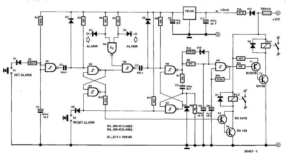
Extremely simple to control, the circuit leaves the car owner 15 seconds to get out of the vehicle after he has set the alarm. Upon return, he deactivates it again by pressing a hidden reset switch within 7 seconds after having opened the car door(s).
Criminals who (hopefully) have not been able to locate the reset switch within the 7 second delay will regale themselves and their accomplices, if any, with a 100 seconds long, intermittent car horn con cert which, ideally, should stop them from pursuing their nefarious activities and, in short, scare them off. Also, the lawful owner of the vehicle is alerted by the horn sound that something is amiss, requiring appropriate action.
The present circuit offers the possibility to connect several types of alarm activating devices, such as a vibration and/or ultrasonic detector, a window breakage sensor, etc., provided these supply an active low output level when an alarm condition exists. However, it is also possible to use the courtesy light switches for this purpose, since these usually connect to the car body when a door is opened. To understand the operation of the alarm, refer to the circuit diagram and assume that the circuit is in the non-activated mode. On leaving the car, the user presses the 'set alarm' button, which leaves him some 15 seconds to actually get out and lock the door(s); the 15 second interval is determined by net work R2-C1; the N2-N3 bistable will toggle after this delay and activate the alarm proper (watch function). Note that this condition may be signaled by a suitable LED driver circuit instead of RE2 as shown in the circuit Only when on of the alarm inputs goes low (i.e. active) will monostable N6-N7 toggle and start a 100 second interval, as deter mined by network R9-C5. However, the horn will not sound immediately, since network R9-C5 provides a 7 second delay to reset (de activate) the alarm before oscillator gate Ns intermittently switches the horn relay transistors T1 and T2. Note that the horn will stop sounding after 100 seconds, but the alarm will remain in its activated state, i.e. any alarm condition signaled by the sensor devices or the door contacts will set it off anew and cause another round of horn sounding.
As already stated, T3, T4, and R13 may be connected to the N2-N3 bistable to provide a LED indication of the activated state of the alarm. Instead of the LED, a relay may be connected to break the ignition coil primary connection. It should be noted, however, that this relay can not be used in cars with electronic ignition; in this case, another means for disabling the car ignition system should be arranged with the alarm in its activated state. The relays employed in this circuit are standard types as available from motorists' shops. The contacts of RE1 are simply connected in parallel with the existing horn relay contacts.
Finally, note that it is of utmost importance to mount the entire circuit and the relay wiring in an out of the way position; the reset switch may be a coded or key operated type and must be fitted well hidden. Current consumption of the circuit in the non-alarm condition is so low as to hardly load the car battery. A voltage regulator section has been added to prevent the alarm from being triggered in error when the car is started.
037 CAR FUSE MONITOR
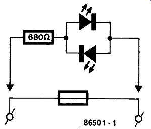
This extremely simple to construct contrivance offers motorists a visible indication as to the nature of malfunctions occurring in the car electric system, which, as we all know or come to find out sooner or later, is protected by means of fuses which have a tendency to melting at times and places most in convenient to driver and his passengers, if any.
This circuit, if constructed with a little mechanical skill, may be plugged across all fuses in the fuse compartment to quickly locate the defective one without having to remove the whole set for visual inspection.
Given the very low cost of the undertaking, it may be worthwhile to fit all fuse-holders with indicators of the type described; in case a malfunction occurs, you are immediately notified which fuse had best be replaced (after the necessary repairs have been made, of course).
-----------
038 CAR LIGHTS MONITOR
Many traffic accidents are caused by failing car lights. Often, the driver is not aware of such a mal function, because the warning lights provided on the dashboard do not, strictly speaking, monitor the relevant lights, but rather the switch position since they are almost invariably connected in parallel with the relevant car lights.
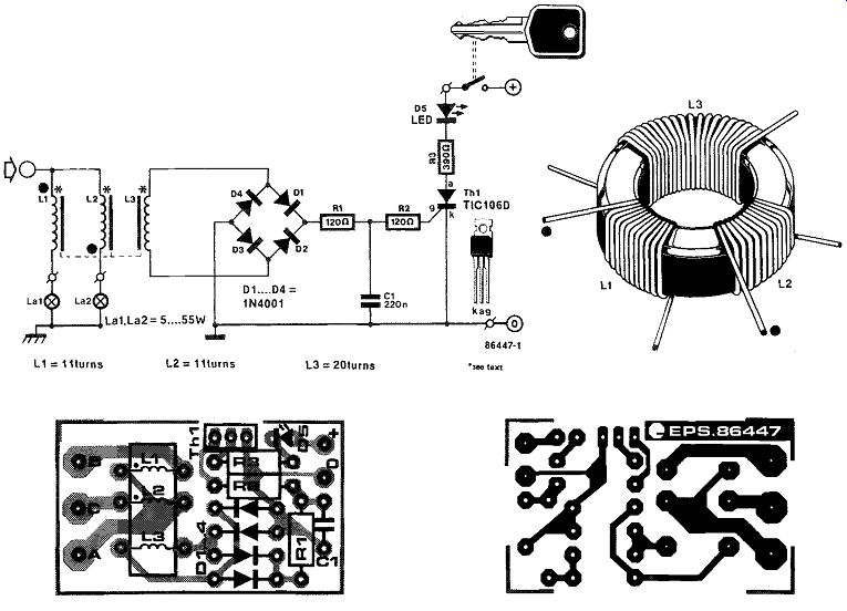
The proposed circuit is intended to indicate the failure of one light in a pair: sidelights; headlights (up to 55 W); rear lights; brake lights; or fog lights.
The two lamps must have the same rating.
Counter-wound coils, L1 and L2, carry the same current when both lamps are working correctly, so that the magnetic fields created by these currents cancel one another. When one of the lamps fails, the magnetic field caused by the current through the other induces a voltage in L3. This pulse causes the TIC106D to switch on, and this in turn makes D5 light. If both lamps fail simultaneously (the probability of which is, however, minute), the circuit does, of course, not function.
Because in practice the two lamps do not come on or go out simultaneously, R1-C2-R2 provide a delay to enable the magnetic field to stabilize. Note, how ever, that C1 must be matched to the particular lamps being monitored: increasing its value makes the circuit less sensitive (longer delay).
The coil is easily made from an old (or new) core of a choke or dimmer switch. First, wind two times 11 turns SWG22 enameled copper wire around the core as shown in the drawing. Inductor L3 consists of twenty turns SWG40 enameled copper wire (this coil does not carry a large current). Note that the black spots in the drawing are the same as those in the circuit diagram. If the circuit does not work, it almost certainly means that the connections of either L1 or L2 have to be interchanged.
To monitor all the lights of car, the circuit will have to be built as many times as there are pairs of lamps.
The indicator diodes are best fitted in the dashboard. It is, however, possible to use only one LED for a number of circuits: when this lights, it is then, of course, necessary to walk around the car to see which lamp has failed. Once the LED lights, it remains on until either the thyristor or the ignition has been switched off.
--------
039 CAR RADIO ALARM I
It is an unfortunate as well as a generally acknowledged fact that the car radio (plus cassette recorder) ranges among the most desirable and often surprisingly easy to steal objects on many a burglar's "shopping list".
This circuit may help to prematurely end the criminal practice by sounding the horn if it is at tempted to remove the radio set; cutting or unplugging an additional ground wire, which has been hid den in the cable for connection to the battery and loudspeaker(s), causes the alarm to be set off, since the connection to the car chassis (ground) is interrupted.
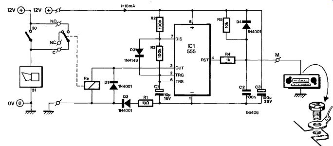
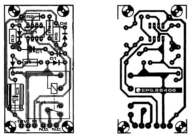
The circuit for the car radio alarm is composed of a single timer, the well-known Type 555, surrounded by a few additional odds and ends to make an astable multivibrator, whose on-time is determined with C1. Horn relay Re should have a coil resistance to enable the timer chip to energize it direct by means of the voltage at output pin 3.
It is seen that the multivibrator is in the reset state as long as point M is connected to earth, i.e. when the set is in the place where it should be. Removing the car radio inevitably causes the voltage at M to rise to nearly 12 V, ending the reset state of IC1, which responds with activating Re, i.e. the car horn, since this is energized via the relay contacts in parallel with the horn switch in the steering wheel.
Note that Re is any small changeover relay having a 12V coil, provided the 555 is capable of handling the coil current; many motorists' and car repair shops can, no doubt, supply you with a suitable relay for the alarm circuit.
The sense wire to point M should be hidden in the multi-wire cable to the radio set, while the circuit itself must be fitted in an out of the way position, somewhere behind the dashboard.
In order that not even an attempt is made to break into your car, it is, as will be readily understood, prudent to stick adhesives to the car side windows, warning of the presence of the radio alarm.
------------
040 CAR RADIO ALARM II
The purpose of this one-chip circuit is to give an audible alarm in case a thief attempts to steal the car radio, which is generally considered an item of prime importance to the motorist's well-being during any trip with his vehicle.
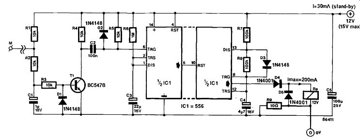
Since removing the car radio necessarily involves cutting or unplugging the supply cables, the present circuit detects disconnection of an extra earth lead, which has been fitted to the rear side of the car radio (metal) housing. In the circuit diagram, this point is marked as M. If M is at earth potential, T; is off (high collector voltage); if the earth connection is cut or unplugged, the voltage at M rises to a positive level, T1 conducts, and a negative-going pulse triggers timer IC1, which has been arranged to provide a 30-second timing interval as defined with R6-C3. The second timer contained in IC; functions as a 0.5 Hz (R7-R8-C4) oscillator section with an output duty factor of 50% (D3). Note that the Type 556 dual timer chip directly energizes a 12 V, low-power relay, whose contacts are connected in parallel with the horn switch in the car's steering wheel.
If it is attempted to steal the car radio, the alarm intermittently sounds the horn for 30 seconds. It is, of course, imperative that constructors of this car radio alarm locate the additional earth connection on the radio set in such a way as to necessitate disconnection at an early stage of attempted theft, otherwise the alarm would come on too late, enabling the thief to get off at his leisure.
---------
041 COURTESY LIGHT DELAY
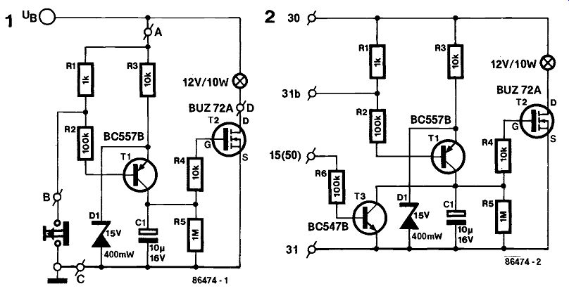
Ever been groping about for the safety belt, ignition slot, choke control or a map while in utter darkness and happy to have closed the car door(s) because of the cold, or foul weather? Wouldn't it be convenient to have the courtesy light on for a few more instants in order to get the vehicle started and ready to move off? Figure 1 shows a courtesy light delay circuit for easy incorporation in almost any type of car. The courtesy light is switched by power MOSFET T2, which is a Type BUZ72A ensuring a low voltage drop (0.2 V typ.) across drain and source and therefore the lowest possible power loss. The door contact, connected to terminals B and C, is normally a push to break type. T1 is therefore off and C-; discharged when the door is closed; MOSFET T2 does not conduct, so that the courtesy light re mains quenched. Opening the door, however, causes T1 to charge C1, and the courtesy bulb will therefore light in a gradual manner. Although closing the door turns T1 off again, C-; continues to supply gate drive to T2 for a few more seconds; the courtesy light will be dimmed slowly. The suggested MOSFET type should not switch more than about 10 W, which is the usual power rating for the courtesy light.
Figure 2 shows how the circuit may be modified to enable the courtesy light to go out immediately after the ignition key is turned. The terminal numbers refer to the wiring code convention as relevant to most types of European car:
15 = + Vbatt- ignition on.
30 = + Vbatt- unswitched.
31 = ground.
31b = door contact (connects to ground).
50 = + Vbatt- starter motor on.
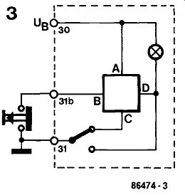
Figure 3 clearly shows the circuit connections in accordance with the foregoing convention.
In case the suggested MOSFET Type BUZ72A (Siemens) is a difficult to obtain item, any equivalent n-channel power MOSFET to the following specifications will also do adequately: Vds-100 V;
Id >_9 A; Pd L 40 W; Rds(on) 5 0.25 Q.
Source: Siemens Components XX (1985) No. 6.
----------
042 FLASHING REAR LIGHT
This rear light for bicycles is fed from a battery charged with current from the dynamo, and starts to flash when the cyclist halts. To preserve battery power, the unit automatically switches off 4 minutes after halting.
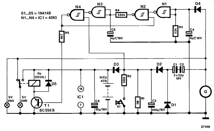
The circuit is essentially composed of a battery charger and a logic switching section. The NiCd battery is charged from a voltage doubler C1-C2- D1-D2-C3 to ensure a charge current of about 20 mA when riding at a reasonable speed. This makes it possible for a charge of 3 mAh to be available after a 10 minute ride, i.e., enough for the light to flash for about 4 minutes after the bicycle is halted. A relay is used to switch between operation while riding and while standing still. When the bicycle is in motion, the voltage from the dynamo, G, ensures that N4 is enabled, so that T1 actuates Re, and the small 6 V bulb is illuminated.
Since C3 is only slowly discharged via R1, N4 re mains enabled for about 4 minutes after halting.
Push-button S1 enables immediately switching off the rear light, because R2 then discharges C3 in a few seconds.
Gate N1 monitors the dynamo voltage, which is rectified by D4-C4-R3. When the direct voltage drops below approximately 2 V, N, switches on multivibrator N2-N3-N4 which causes the relay to toggle at a rate determined by R4-05. The 5V DIL relay requires only 11 mA, while the current consumption of the 4093 is virtually negligible at about 1 µA.
It should be possible to fit the circuit and the battery in a somewhat larger than normal bicycle headlight, equipped with terminals for connecting the dynamo and the rear light. Of course, due care must be taken to avoid the battery contacts touching the metal inside of the light.
--------------
043 GARAGE STOP LIGHT
A novel use of solar cells makes positioning your car in the garage rather easier than old tires, a mirror, or a chalk mark.
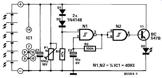
The six solar cells in figure 1 serve as power supply and as proximity sensor. They are commercially available at relative low cost. The voltage developed across potentiometer Pl is mainly dependent on the intensity of the light falling onto the cells. The circuit is only actuated when the main beam of one of the car's headlights shines direct onto the cells from a distance of about 200 mm (8 inches). The distance can be varied somewhat with P1.
Under those conditions, the voltage developed across C1 is about 3V, which is sufficient to trigger relaxation oscillator N1. The BC547B is then switched on via buffer N2 so that D3 begins to flash. Diodes D1 and D2 provide an additional in crease in the threshold of the circuit. The total voltage drop of 1.2 V across them ensures that the potential at pin 1 of the 4093 is always 1.2 V below the voltage developed by the solar cells. As the trip level of Ni lies at about 50 percent of the supply voltage, the oscillator will only start when the supply voltage is higher than 2.4 V.
The circuit, including the solar cells, is best constructed on a small Veroboard as shown in figure 3, and then fitted in a translucent or transparent man made fiber case. The case is fitted onto the garage wall in a position where one of the car's headlights shines direct onto it. The LED is fitted onto the same wall, but a little higher so that it is in easy view of the driver of the car. When you drive into the garage, you must, of course, remember to switch on the main beam of your headlights! A descriptive article on the operation and use of solar cells appeared in the June 1985 issue of Electronics: solar battery--p. 6-65.
044 HALOGEN LAMP PROTECTOR
Halogen lamps are, unfortunately, rather prone to burn out when they are switched on, and this is mainly owing to the high current consumption of these devices during the initial stage of heating up to the normal operating temperature of the filament in haloid gas.
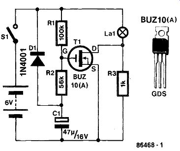
A typical value for the cold resistance of a 6 V-4 W halogen lamp is about 0.3 ohm, demanding a turn-on current of 20 A. In view of the relatively low internal resistance of car and motorcycle batteries, such a current surge is not at all to be dismissed as purely theoretical, and it is easily seen that the ensuing rapid heating inside the lamp is a prime cause for the thin filament to melt at the sudden temperature effect. What is required, therefore, is a series regulator system to limit the current during the heat-up phase; in other words, a soft turn-on facility.
-----------------
The circuit diagram shows that C1 is charged to the battery voltage by means of It and R2, causing FET T, to become slowly conductive after S1 has been closed. The Type BUZ1O(A) power FET is used in view of its low drain-source resistance in the fully conductive state; a typical value for Rds(op) is 0.19 ohm, which ensures a low voltage drop across the FET, and, therefore, a sufficiently high operating voltage for the halogen lamp. Parts D1 and R3 discharge C1 after opening S1, so that the power-on delay functions correctly any time the lamp is turned on.
Lamp voltages other then 6 V require R2 to be modified according to R2 = 200,000/(Vbatt- 2) [ohm].
In case the BUZIO(A) proves hard to obtain, other types of n-channel power MOSFET may be used in the circuit. The minimum requirements are: drain-source voltage V_ds = 50 V, drain current Id = 19 A, and drain-source on resistance Rdson = 0.2 ohm.
045 LED REVOLUTION COUNTER
A close look at the dashboards of a number of cars may reveal the use of three basic types of rev counter: first, the still most commonly found needle and round scale, analog combination; second, a set of digital displays (often LCDs); and third, a pseudo-analog meter in the form of multi colored LED bar, looking much the same as a LED-based VU meter on modern recording equipment.
-----------
------------
Parts list
Resistors:
R1 ... R4; R6:R11 =47 k
R5; R10= 100 k
R7= 270 k
R8= 1 k
R9= 10 k
R12= 220 k
R13=4.7 ohm
P1; P2= 100 k preset
Capacitors:
C1;C4=10 n
C2= 4n7
C3= 100 n
C5= 100 u;16 V
C6=10 u;16 V
C7= 1 u;16 V
C8=47 u;16 V
C9=470u; 25 V
Semiconductors:
IC1=555
IC2 = L4810
IC3=U1096B (Telefunken)
D1 ... D60=LED (see text)
D61 = zener diode 8V2; 400 mW
D62 = 1N4001
T1 =BC547B
Miscellaneous:
PCB Type 86461
------------
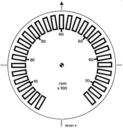
The circuit presented here belongs to the third category. However, contrary to the straight LED bar indication, this design features a round scale with a colored LED needle imitation, just as the good old mechanical rev counter.
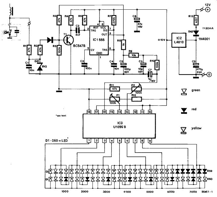
The circuit is based on the Telefunken Type U1096B analog input LED driver which can light one of 30 LEDs on the rpm scale, whose lower and upper indication limits may be set to individual requirements; e.g. the 30 LEDs may merely indicate a limited rpm range to attain a higher resolution.
The circuit diagram shows IC1 to receive the con tact breaker pulses and to reshape them for conversion to an analog voltage in an R-C filter, which passes the signal to the input of the LED driver.
The detailed operation of the circuit is as follows.
Zener diode D61 and parallel capacitor C1 safeguard the base of inverter transistor T1 against receiving high voltage pulses induced in the ignition coil secondary winding. The Type NE555 timer has been configured to function as a monostable with an output pulse period time of 3 ms, during which time R3 causes T1 to conduct so as to prevent erroneous triggering of the monostable. The analog voltage, proportional to the engine rpm rate, is established by means of smoothing network R8-C5, R9-C6 and R10-C7. The indication range for the LEDs may be set with Pi and P2, the presets for the lower and upper limit, corresponding to LEDs D1-D2 and D59-D60 respectively. Note the relative simplicity of the LED array connection to IC3; only nine IC output lines suffice to drive any one of 30 pairs of LEDs, whose color may be chosen to individual taste, while it is also possible to use series-connected LEDs to achieve a brightly as well as functionally lit rpm scale.
The circuit diagram shows two rows of LEDs; the upper one is the normal rpm indication scale, for which the following colored subdivision may be used: 0 to 5000 rmp are green LEDs; from 5000 to 6000 rpm yellow or orange types; 6000 rpm and up are bright red types. This range and subdivision may, of course, be adapted for the specific type of engine.
The lower row of LEDs may be used to indicate a number of fixed rpm rates on the scale, for instance at 1000 rpm intervals.
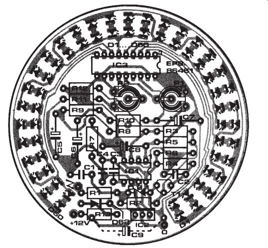
The PCB track layout and component overlay with this design should enable anyone to readily con struct the LED scale revolution counter, but note that the LEDs are mounted at the PCB track side to get the correct indication in clockwise direction with increasing the rpm rate. Also note the use of the low voltage-drop regulator IC2 which supplies IC1 and IC3 with a stable, noise-free 10 V rail.
046 MOTOR-CYCLE GEAR INDICATOR
This circuit provides motor-cycle riders with a gear indication to the foot-operated lever at one side of the engine block. The proposed indication unit will be appreciated by those riders in the habit of forget ting which gear they have selected when attempting to drive off at traffic lights or crossroads and finding that the engine stalls because it had been switched to second gear.

---------------
The circuit as shown is based on the use of two gear-lever operated, plunger or roller type microswitches, along with the neutral gear indication lamp, which is a standard item on most types of modern motor-cycle.
Bistables N1-N2 and N3-N3 serve as debouncer circuits for micro-switches S1 (lever down) and S2 (lever up). If either one switch is actuated, N14 or N15 will cause bistable N12-N13 to be set or reset; counter IC5 counts up (U/D = 1) or down (U/D =0) as a result of actuating S2 or S1 respectively. On release of the relevant microswitch, AND simulator D1-D2-R6 supplies ICs with a clock pulse, incrementing or decrementing the gear readout composed of IC6 and the indication-panel mounted 7-segment LED display.
Input pin 5 of gate N6 may be wired to point A, B, or C to suit 4-, 6-, or 5-gear types of motor-cycle respectively. N6 inhibits OR gate Nis from supplying further clock pulses if S2 is operated when driving in top gear. N16 and Nit have the same function for the bottom gear, preventing the counter from decrementing the display reading at gearing up from neutral to 1.
If the neutral switch-S- is closed, IC8 supplies the A and B inputs of 106 with logic low levels; the level at the C input need not be forced low, since the neutral gear is in between first and second, both of which positions cause the most significant bit –C- to be low anyhow.
Parts R5-C2-N10-N5 have been included to prevent an erroneous display reading at gearing down from 2 to neutral and up again; for two seconds, Nis is disabled from clocking 105, so that the lever-up pulse is not detected.
At power-on, R7 and C3 preset counter 105 to state 1.
In conclusion, it goes without saying that S1 and S2 should be good quality microswitches, sealed against moisture and dirt.