132 BLOW THAT SYNTHESIZER!
Circuits for generating electronic music are usually controlled by key switches. Not only do keyboards offer the simplest technical solution for producing fast changing, reproducible tones over a wide frequency range, but they also enjoy tremendous popularity because they are considered to be easier to learn to play than string or wind instruments.
Because of that, we have not tried to create an electronic oboe, flute, or clarinet with the present circuit. In any case, the technical intricacies associated with such instruments would make their electrophonic counterpart prohibitively expensive.
So, what we have got here is the relatively simple facility of converting breath power into a proportional analog voltage with which the volume of a music synthesizer can be controlled; the tones remain con trolled by the keyboard switches. No doubt, many of you, ingenious readers, will be able to think of various other applications of the converter.
The circuit does not operate direct from the exhaled breath, but from the noise generated by this. A thin, flexible tube, to which a mouthpiece may be attached, leads into a closed box, in which not only the circuit, but also an inexpensive microphone have been fitted.
The noise received by the microphone is amplified in IC1, the gain of which can be adjusted with P1, and subsequently rectified by IC2-D1-D2. An active low-pass filter removes most of the ripple from the output voltage.
To keep the circuit as simple as possible, we have opted for a compromise between input sensitivity and output ripple: the relation between these two properties can be adjusted with P2 If you have an oscilloscope with slow sweep, calibration of the converter should present no problems.
First, adjust the value of P1 so that the output voltage with hard blowing into the tube just does not cause full drive (dependent on the sensitivity of the following instrument).
Second, adjust P2 so that the output signal is relatively free of ripple, while the converter still reacts to normal breathing. A steeper filter would have been better here, but that would have increased the cost.

-----
133 DISCO SOUND LIMITER
The environmental nuisance value of discos is in direct proportion to their sound level. The circuit proposed here cannot be disabled by the disc jockey, since it is built into the output amplifiers used in the disco. Its operation is amazingly effective: if the preset sound level is exceeded, the input of the amplifier is short-circuited for a few seconds. Any disc jockey whom that has happened to a couple of times soon gives up trying to break the sound barrier.
The power amplifier output is connected to the metering input of the present circuit (C1). This signal is applied to low-pass filter Ra-C2 via P1 (which sets the maximum volume) and buffer IC,.
In case of line inputs, this opamp can be given a gain of 20 dB by the omission of the wire link across R2.
The signal from the low-pass filter is rectified (half wave) by IC2 and IC3. The resulting direct voltage is applied to A1 and A2 which compare it with two reference voltages derived from potential divider R8-R9-R10. When the first threshold is exceeded, D5 lights to warn that maximum sound level has almost been reached. When the sound level then in creases by 6 dB, A1 also toggles, which triggers monostable IC5.


------------
The input signal to the power amplifier (via C9, Rio, and P2) is then short-circuited to ground via Resistors R14 and R15, and capacitor C8, obviate any "plops" from the loudspeakers.
Power for the present circuit may be derived from the output amplifier. The normally quite high supply voltage there is reduced to ± 15 V by two complementary power transistors. Current consumption of the circuit is about 40 mA.
134 GUITAR FUZZ UNIT
The fuzzbox, fuzzer, tube screamer, or whatever other name there may exist for the controlled guitar sound distortion unit, is a well-known item in the electrophonic field, which is of common interest to both musicians and electronics enthusiasts.
The majority of fuzz units are simply opamp configurations with some form of maximum input level control, which determines the degree of overdrive by the guitar input signal, and, consequently, the amount of audible distortion, generally referred to as the object "sound" the player has in mind as his very own musical visiting card.
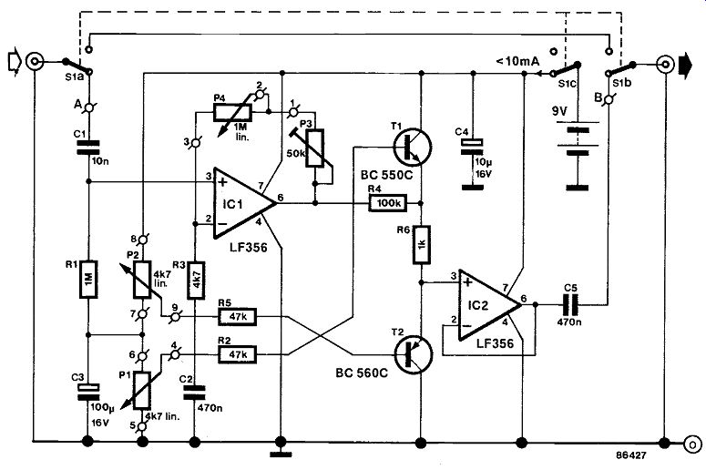
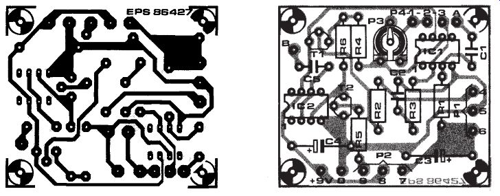
This is probably one of the few fuzz units to feature controllable symmetrical clipping facilities, which means that the limit for distortion-free amplification may be separately defined for both the negative and positive portions of the input sinewave(s), the peaks of which may be clipped by means of shunt transistors T1 and T2 respectively, each with its own clipping level control potentiometer (P1; P2). The transistors, when driven, pass the signal from input opamp IC, to the positive supply or to the ground rail, before buffer IC2 can pass the "fuzzy" guitar sound to the connected amplifier.
Preset P3 determines the minimum gain of the fuzz unit; the desired level may be set with P4 turned to its minimum resistance position. Next, P4 is adjusted to suit the maximum input level that can be expected from the guitar. P3 and P4 may then be alternately adjusted to hit the correct compromise between these two signal levels.
Finally, note the three-pole changeover switch which allows easy bypassing of the fuzzer while simultaneously switching it off to preserve battery power.
---------
---------
135 LIMITER FOR GUITARS
The basic dynamic characteristic of a chord can be analyzed as a fast rising, needle-shaped pulse with a virtually exponential decay-see Fig. 1. This typical amplitude characteristic can only be faithfully reproduced by an amplifier if this is operated well below its overload margin, and that, many guitar players know, generally results in too low an average sound level. Also, when it is desired to use a high volume setting, the distortion soon rises to an unacceptable level. Although the above difficulty is widely remedied by means of a tightly set compressor or limiter, the sound may then lack the required aggressiveness. This circuit is expected to give better results than most other limiters, because it is only active in the upper range of the dynamic characteristic.
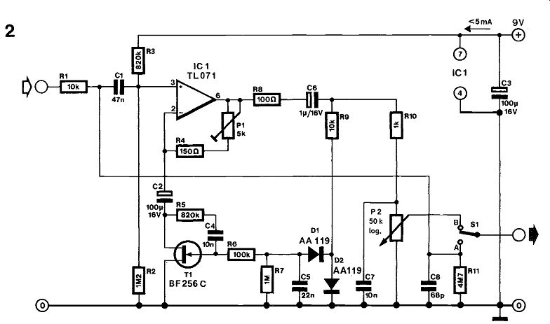
The gain of the preamplifier set up around IC1 is adjustable with Pt. The inverting input of the opamp is grounded via the drain-source junction of n-channel FET T1 which operates as a voltage-controlled resistance here, and is driven with a negative gate voltage derived from the limiter's out put signal. The gain of the opamp is there fore inversely proportional to the gate voltage of the FET, whose drain-source resistance is reduced as the gate voltage becomes more negative. Network R5-C4 effectively reduces the distortion incurred by the regulating action of the FET. It may be necessary to re-dimension R5 and C4 to compensate for the tolerance on the FET-use an oscilloscope and a function generator to find the optimum values for these components while the circuit is being arranged to operate at maximum compression.
The limiter is fairly simple to align. Apply a 1 kHz, 150 mV input signal to the input, and monitor the output signal with an oscilloscope. Adjust P1 such that maximum amplification is obtained with virtually no distortion. Increase the input amplitude to 300 mV: this is likely to make some distortion noticeable. Carefully turn P1 back until the distortion is reduced to an acceptable level. In some in stances, when the distortion remains too high whatever the setting of 111, it may be necessary to replace T1 , since the Type BF256C is manufactured with a relatively loose tolerance.
The proposed limiter leaves the lower dynamic range unaffected, while slightly compressing the peak amplitudes in the input signal. Optimally aligned, it suffers none of the notorious side-effects such as "noise breathing" and clipping commonly associated with other units, while it enables guitar amplifiers to be driven 3 dB harder without producing appreciable distortion.

---------------
136 MELODIC SAWTOOTH
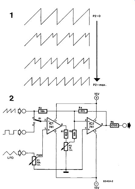
Even in this era of programmable, polyphonic synthesizers, interest in simple, monophonic keyboard instruments remains. Many FORMANT owners are still proud of their, probably first, home-built synthesizer and are still on the lookout for new circuits for the generation of exotic sounds. For all those, here is an easy-to-build circuit that can convert a sawtooth signal at its input into an output of double the frequency and half the peak value of the input signal (figure 1).
Comparator IC, transforms the sawtooth signal into a rectangular signal (see figure 2). Adder IC2 combines the original input signal and the rectangular signal.
An additional LFO (low frequency oscillator) connected as shown provides pulse-width modulation of the rectangular signal, which has a greatly beneficial effect on the output signal.
When switch S1 is set to position b, it is possible to inject a rectangular signal whose frequency is in dependent of the sawtooth frequency, which greatly increases the number of melodic variations, as anyone acquainted with synthesizers knows.
Power requirements can be met direct by the FORMANT or any other ± 15 V symmetrical supply. Current consumption is not higher than 10 mA.
---------------
137 METAL PERCUSSION GENERATOR
The objective of this circuit is to obtain a synthesizer-controlled equivalent sound as produced by such metal indefinite pitch percussion instruments as cymbals, gong, and anvil. Fig. 1 shows that the generator comprises four independently tuneable VCOs which supply rectangular output signals to a combination of XOR gates.
One of four identical KOV (keyboard output voltage) driven VCOs is shown in Fig. 2. The use of fast opamp types ensures linear VCO operation well up to 4 kHz, while FET T, improves upon the linearity of the voltage-frequency curve relevant to the combination of integrator and comparator.
With the VCO constructed four times over and connected as shown in Fig. 1, drive controls P1 . . . P4 allow the user to set the output sound as desired.
The outputs of buffer opamps A1 .. . A4 (IC,, Type TL084) should measure 0V offset with the KOV rail grounded. If this can not be attained, the IC will have to be exchanged with a more stable type.
Linearity of each of the VCO circuits is set with the preset at the drain of the FET, P5 and T1 respectively in Fig. 2. Use a scope to check whether the rectangular VCO output signal has a 50% duty factor; if not, adjust the relevant preset.
As the four VCOs lack a linear to exponential KOV converter at their inputs, it is not possible to use the present circuit with a keyboard of the 1V per octave type. However, many keyboards provide an exponential KOV signal whose frequency doubles with every octave and which are, therefore, suitable for use with this generator.

-------------
138 PATCH CATCHER
This circuit facilitates switching between programmed settings on synthesizers, expanders, and other electrophonic instruments. Most of these have some provision for storing or saving user-defined instrument settings, which are usually referred to as patches in the electrophonics enthusiasts' jargon. Although this facility is a great asset to many musicians, a problem arises when patches are to be called up in rapid succession while playing. On some instruments, this problem is solved by a pedal that, when pressed, enables the instrument to operate with the next patch from the user-defined file (patch increment pedal). In practice, however, the increment function of the pedal may still be considered cumbersome. Assuming that the relevant instrument supports the use of eight patches, the pedal needs to be pressed no less than seven times to switch from, say, patch 3 to 2. This is obviously a distracting additional task when the keyboard is to be played simultaneously.
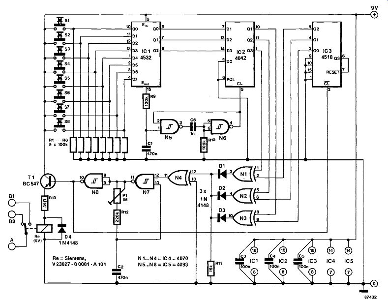
This circuit uses a relay whose contact is connected to the pedal input on the instrument. The user presses a key numbered 1-8 to select the relevant patch, and the circuit arranges for the relay contact to be automatically actuated, simulating the number of pedal operations that would be required otherwise. With reference to the circuit diagram, IC, is a priority encoder whose outputs Qs-Q2 supply the binary code of the pressed key S1-S8. The pulse at therminal E001 is delayed in Rs-C, and fed to Ns-Ns which serve to clock 4-bit latch IC2. Out puts Q1-Q3 of this chip are applied to the inputs of XOR gates N1-N3, together with the outputs of counter IC3, whose binary output state is initially assumed equal to that of IC2. Pressing one of switches S,-So causes the output of IC2 to change, and one of the XOR outputs to go high. This enables oscillator N7, so that its output pulses, inverted in Na and buffered with T, energize the relay and increment the patch number on the instrument. The oscillator pulses are also applied to binary counter IC3, which is set up to count from 0 to 7 because its Q3 output drives the RESET in put. After a maximum of 7 pulses, the logic levels applied to each of the XOR gates are equal again, so that the oscillator is disabled via N4.
The choice between the make or break contact of the relay is governed by the type of pedal this circuit is to replace. Preset P1 is adjusted such that the instrument is just capable of reliably following the actions of the relay. After turning on the equipment, it is necessary to first press Si, then select the first program on the instrument, and finally make the appropriate connection between this and the patch catcher.
The circuit, exclusive of the relay, consumes only a few milliamperes. The prototype, fitted with the stated Siemens relay, drew a mere 50 mA from the 9 V supply.
----------
139 QUARTZ-CONTROLLED TUNING FORK
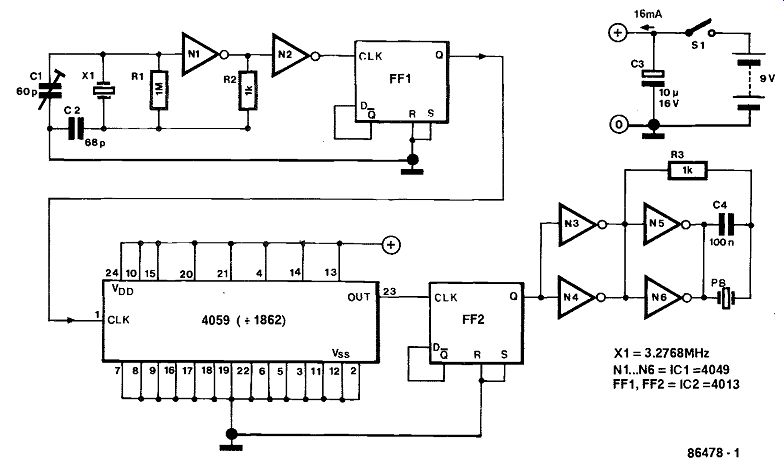
Musical instruments are tuned with the aid of a signal source that generates a signal at a frequency of 440 kHz. An electronic tuning fork is superior to its mechanical counterpart as far as dimensions, weight, and stability with temperature are concern ed. The stability is obtained by controlling the signal source by a quartz oscillator. The output of the oscillator is frequency-divided and then amplified. The output may be made audible by, for instance, a small loudspeaker.
In the accompanying diagram, N1, N2, and the quartz crystal form the oscillator. The precise frequency, measured at the ohm terminal of FF2 with a calibrated frequency meter, is set with C1. Divider Type 4059 is easily Programmed to a different divisor. A duty factor of 50 per cent is ensured by FF2.
The transducer is shunted by a 100 nanofarad capacitor, because most transducers have a much better high- than low-frequency response, which causes very shrill sounds.
-----------
140 SOUND-LEVEL INDICATOR
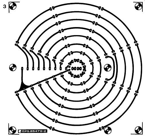
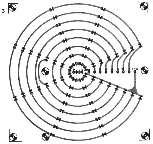
This novel indicator is ideally suitable for use in a discotheque. It consists of eight equi-distant columns of eight LEDs arranged in a star-like pat tern, so that corresponding LEDs in the eight columns form concentric circles, as shown in figure 1b. The higher the sound level, the more circles light, giving the impression of a star of constantly varying brightness.
As can be seen in figure lb, the eight LEDs in any one of the eight circles are connected in series. Each of these series chains is driven by a transistor:
T1 .. .T8 in figure la. Dropping resistors are not required: the positive supply voltage provides just over 1.8 V per LED, which is a perfect value for red LEDs to show up nicely.
Transistors T1... T8 are driven by differential amplifiers A1 . . A8, which compare the audio-dependent direct voltage across C2, which is buffered by A12, with the potential determined by D1 and R . .RA8. If the result of the comparison is positive, the associated driver transistor is switched on, and the appropriate circle of LEDs lights. The LED in the center, D4, is driven by T% and only lights when the sound level is very low.
The direct voltage across C2 results from full-wave rectification in A10 and A1 i of the input signal after this has been amplified in A9. The input sensitivity is about 600 mV for saturation, i.e., to light all sixty four LEDs; it can be increased by lowering the value of R2.
The speed with which variations in sound intensity are indicated depends on the value of C2: if this is 10 uF, the light pattern changes slowly, whereas when the capacitor is omitted, it reacts instantly to different sound levels.
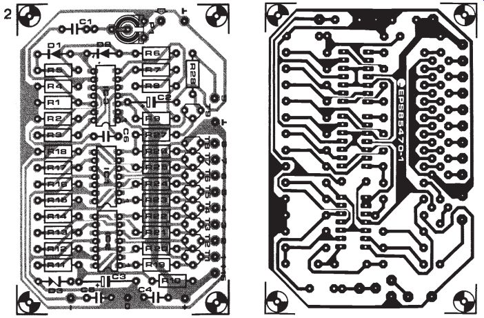
The indicator is constructed on two printed circuit boards (figures 2 and 3). The LED board in figure 3 has not been provided with a component layout because of aesthetic considerations. The layout is, however, given on the PCB in figure 4 for those who want to use it all the same. The two boards can be fitted together with the use of spacers: appropriate holes have been provided for this in a manner which ensures that the 11 terminals for interconnections on the boards are opposite one another.
An interesting optical effect arises when a sheet of red perspex is mounted in front of the LED board.
Refraction in this material causes the LEDs to show up as sources of diffused, rather than pinpointed, light.
The current consumption of 800 mA at saturation may be reduced by lowering the supply voltage to, say, 12 V, but this will, of course, reduce the brightness of the display.
Parts list
Resistors:
R1 = 270 k Ri*, R14 = 10 k R3 = 100 k Ra . . .Rs, Ris. . .R27 =
15k R9 = 22 k
R19 = 1k8
R11, R12 = 27 k
R13 = 18k
R15 = 8k2
R16 = 6k8
R17 = 2k2
R18= 1k
Res = 820
= preset potentiometer, 250 k
Capacitors:
= 560 n
C1* = 0...10 µ/16 V
C3 = 47 µ/16 V
C4 . . . C6 = 100 n
Semiconductors:
T1 ...To = BC550C
T9 = BC560C
D1, D1 = 1N4148
D3 = zener diode 5V6/400 MW
D4 . . . D69 = LED red
IC1,IC1 = LM324 IC3 = TL084
* = see text PCB 85470-1 85470-2

-------------
-----------
--------------
141 SWELL PEDAL
Reminiscent of the accelerator pedal in a car, a swell pedal enables musicians to alter the sound volume by foot, since they invariably need both hands to play their instrument. Electronic organs have the swell pedal normally built into the front near the other pedals. Guitarists have to buy this almost in dispensable aid for getting the right blend of accompaniment and solo voice(s) as an optional extra.
From an electronic point of view, such commercially available devices are simplicity itself: normally nothing more than a potentiometer operated by the foot pedal via a toothed bar. The mechanics, how ever, make home construction a rather more daunting task. The swell pedal described here avoids the mechanical intricacies.
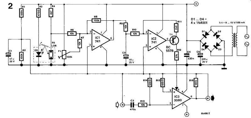
The circuit is entirely contained in a flat case of about the shoe-size of the user- see figure 1. A wedge-shaped, hollowed-out piece of foam rubber is glued onto the lid of the case. A light-emitting di ode, D5, and a light-dependent resistor, LDR, protrude from the lid. A small sheet of metal or plastic, the underside of which is covered with white paper or cardboard, is then glued onto the foam rubber.
The top of the metal or plastic sheet may be covered (glued) with a small rubber mat.

--------------
When the foam rubber is compressed by foot pressure, the reflective white paper or cardboard comes nearer to the LED and LDR, which causes the resistance of the LDR to diminish. Because of the amplifying, inverting, and compensating action of IC1, a voltage is applied to IC2 which is used to control the drive current provided by transistor T1 for OTA (operational transconductance amplifier) IC3.
After the pedal box has been glued together, so that the electro-optical components are in a light-proof chamber, adjust P1 so that with non-operated pedal the sound volume is just at the right level for accompaniment. For solo playing, the pedal is depressed as required to obtain the increased sound volume. It is advisable to fit P1 in the side of the pedal case as shown, so that it can be re-adjusted at a later date if required.
142 WAH-WAH BOX FOR GUITARS
--------
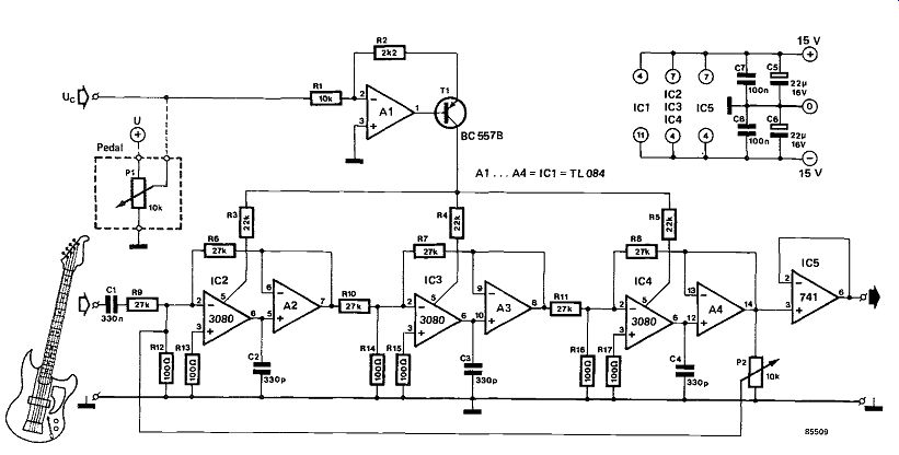
In this day and age of electrophonics, a wah-wah box is still a popular means of animating an other wise tired sounding guitar. Such a box, which is basically a high-Q low-pass or band-pass filter, can be designed in various ways. Early designs were in variably based on active (transistorized) double-T filters.
The present circuit, using opamps and operational transconductance amplifiers (OTAs), is rather more complex but also more efficient and more reliable.
Three pairs of opamps, each consisting of an OTA and a buffer amplifier, in conjunctions with capacitors C2, C3, and C4, form a low-pass filter.
Since the usual series resistances have been replaced by voltage-controlled current sources (OTAs), the roll-off frequency of the filter is determined by the currents flowing into pin 5 of the 3080s. These cur rents are themselves directly proportional to the input control voltage, Uc, which has been converted in A1 and T1. This voltage, which is derived from a swell pedal, can have any value between 0 V and about 12 V.
The negative feedback from output to input enables the ohm of the filter to be set with P2 The swell pedal may be constructed as described elsewhere in this issue: it can actually be installed in one case together with this wah-wah filter! As it is difficult to describe sounds, and we are sure that the guitar players among our readers will in any case experiment themselves, we will not dwell on what to expect from this musical adjunct. No calibration is needed: the box works or it does not!
---------