167 AUTO FOCUS FOR SLIDE PROJECTOR
This circuit is intended as a replacement for the electronics in a partly or wholly defective autofocus driver in a slide projector. The mechanical parts in the autofocus system are assumed to be still functional.
Most automatic focusing systems in slide projectors are based on the use of an optical module, which comprises a small lamp, a few lenses and mirrors, and a light sensor made from two series-connected light dependent resistors (LDRs), which function as a potential divider. As shown in Fig. 1, lamp La projects a narrow beam onto the center of the slide, A, whose surface reflects it onto the LDRs.
When the slide surface bulges inside or outside, the projected image on the screen is blurred, and the beam from L is received on the surface of one of the LDRs (point 2 or 3). This is detected by a motor driver circuit, which ensures that the focal distance between the objective, 0, and the slide surface is corrected to maintain a sharp image, i.e., the objective is moved until the circuit detects that the reflected beam from L falls exactly in between the LDRs (point 1).


------------
The circuit is based on the use of an existing set of LDRs as part of the optical module in the slide projector. The symmetrical supply shown to the left, and the motor plus decoupling capacitor, are also part of the projector. The inverting input of opamp IC, is at ground potential when the above mentioned test beam falls in between the LDRs. The output of the opamp keeps the non-inverting input at 0 V as well, so that no motor voltage is available at the emitters of power drivers T1-T2. Should the reflected beam illuminate either one of the LDRs, the circuit arranges for the motor to move the objective glass towards the correct focal position, until no voltage difference between the LDRs is detected.
The feedback gain of the circuit has been kept relatively low to keep the motor from continuously moving the objective glass past the target position, causing the system to oscillate slowly. Resistors R3 and R4 may have to be dimensioned differently than shown to achieve optimum response as regards speed and stability.
168 DIGITAL JOYSTICK INTERFACE
----------
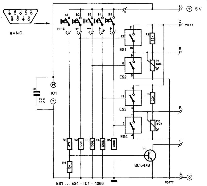
The BBC and Electron computers produced by Acorn have a joystick port to which only analog joysticks can be connected. For many purposes, a digital joystick, i.e., one with four contacts, is much more suitable. The interface suggested here enables a digital joystick to be used with the two computers mentioned.
The joystick port is provided with a voltage of 1.8V when the analog joystick is set to the left or top positions, 0 V with the joystick in the right or bottom positions, and 0.9 V with the joystick in neutral. The 1.8 V is the reference voltage of the analog-to-digital converter in the computer.
As can be seen from the circuit diagram in figure 1, the various voltages can simply be provided by four sets of contacts or switches. Each of the sets of contacts controls an electronic switch. The 0.9 V for neutral is obtained from a potential divider. The electronic switches are required because the contacts in the joystick have a common connection and can, therefore, not be used direct for shorting resistors in the potential divider. The fire button is connected to the + 5 V line by a junction in the joystick, and thus produces a logic 1 when it is pressed, whereas the computer expects a 0. The signal is, therefore, inverted by transistor T1.
The interface is calibrated with the aid of a small auxiliary program: REPEAT PRINT ADVAL(1) ADVAL(2): UNTILO
Potentiometers P1 and P2 should be set to the center of their travel.
Connect the joystick and the interface to the computer, start the auxiliary program, and adjust the potentiometers so that the two numbers on the screen are as near as possible 32768.
Table 1.
Interconnections interface to computer
terminal joystick 1 joystick 2
A 8 (gnd) 8 (gnd) B 7 (ch.1) 4 (ch.3) C 11 (Uref) 11 (Uref) D 1 (+5 V) 1 (+5 V) E 15 (ch.0) 12 (ch.2) F 13 (PBO) 10 (PB1)
169 ELECTRONIC TOSS-UP
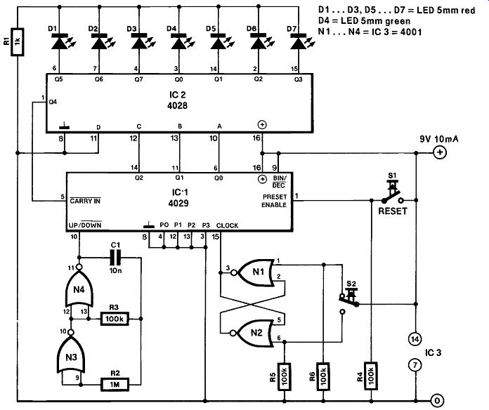
The electronic version of the well-known coin to toss up prior to commencing a football match-or any other sports event where there is a generally established formality on part of the referee-consists of a row of seven LEDs, the center one being green, the others red. After having reset the circuit, the odds are exactly equal for either one red LED located next to the green one to light when the toss up key is pressed; we have, therefore, a left/right decision circuit operating on the basis of pure arbitrariness.
As to the operation of the circuit, button S1 may be pressed at any time to preset counter IC1, which responds with outputting the binary code for 0 at its Qe, Q1 and Q2 outputs, causing BCD-to-decimal decoder IC2 to light the corresponding LED, i.e. the green one-D4-at the center of the row. The preset code for the initial state of the circuit is determined with preset inputs P. . . P3 being tied to ground, causing IC, to load 0000 as the binary start-up value when S1 is pressed.
Depression of button S2 causes the bistable composed of Ni and N2 to toggle, providing a single pulse transition at the clock input of IC,. Depending on the logic level at the UP/DOWN input of IC,, the one-of-eight decoder will light either D5 (right) or D3 (left), since counting up from 0000 gives the next higher binary code 0001, while counting down gives 1111. The latter value causes IC2 to light D3 at the Q7 output, since the most significant bit input-D-has been tied to ground.
The arbitrariness of the toss-up circuit is ensured by the speed at which oscillator N3-N4 applies pulses to the counter UP/DOWN input. The odds are 1 to 1, theoretically, while the circuit can not be bribed . .
Seven of the eight active-high outputs of IC2 have been wired direct to the corresponding LED, while Q4 serves to inhibit the counter via the CARRY IN terminal. It is readily seen that counter inhibiting occurs automatically when IC, counts up from out put state 3, or down from state 5; both conditions cause Q4, and therefore CARRY IN, to go high, disabling further counting until the reset button is pressed.
Finally, repeatedly depressing S2 without resetting the circuit will cause any other, random, LED in the row to light, and this facility may be put to good use in any other, random decision based game or serious application you have in mind.
----------
170 FLASHING LIGHTS
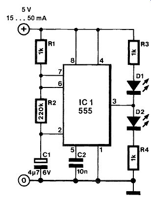
This application of the well-known Type 555 timer is intended for model railway enthusiasts wishing to construct a two-lamp flashing beacon with a minimum of components.
With reference to the circuit diagram, the number of LEDs need not be restricted to two: several may be connected in parallel to achieve a higher light intensity, but a total current consumption of 200 mA should not be exceeded to prevent the destruction of the output stages in the 555. Each LED added should have its own current limiting resistor, similar to D1-R3 or D2-R4.
The flashing rate is defined with C1, The stated value of this component is likely to be optimum for applications in model railways. The supply voltage for the circuit is not critical, but should remain within the range from 5 to 10 V. With two LEDs fitted and a 5 V supply, the flashing circuit should consume less than 50 mA. The intensity of the LEDs can be adapted to individual preference by changing R3 and R4, but too low resistance values should be avoided to prevent the destruction of the LEDs.
--------
171 HALOGEN LAMP DIMMER

--------
--------
Parts list:
Resistors ( ± 5%1:
R1 =470R; 0.5 W
R2;R7=100K
R3 = 22K
R4 = 330K
R5 = 150K
R6=270K
R8=82K
R9 = 150R
Capacitors:
C1 =470µ; 16 V; axial
C2 = 1;4; 16 V; axial
C3 = 1n5
Semiconductors:
DI =1N4001
Tri1 =TIC236 or TIC246* IC, =TCA280A
Miscellaneous:
PCB Type 87452
Heatsink for Irk.
* See text
The circuit proposed here is suitable for fitting into slide projectors without a dimmer facility (24 V AC fed halogen lamps). With a few small alterations, it can also be used for dimming 12 V halogen lamps, but not those in a car, because these are fed from a DC source. The circuit shown in Fig. 1 is intended for operation from a 24 V AC supply, and can handle a lamp load of up to 150 W For loads up to 250 W, the TIC236 should be replaced by a TIC246.
The illumination of the halogen lamp is controlled by applying a direct voltage to pin 5 of dimmer chip IC, . A voltage of + 2.5 V gives maximum illumination, while +5 V results in the lamp being turned off completely. The lamp intensity control range-2.5 V to 5 V-can be extended upwards by decreasing the value of C2.
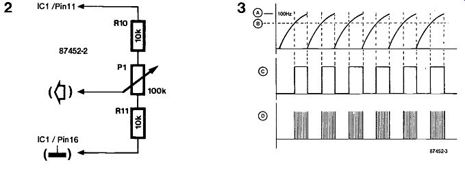
The TIC246 should be used when the circuit is to control a 12 V lamp that consumes more than 50 W. Figure 2 shows details of the connection of a potentiometer to the intensity control input of the TCA280A. Voltage divider R10-Pi-R11 is fitted externally and can be fed from the stabilized voltage available at pin 11 of IC1. The minimum and maximum intensity of the lamp are determined by R10 and R11, respectively, so that the control range can be dimensioned to individual preference. When potentiometer control is used, C2 must always be 100n.
Figure 3 shows the signal waveforms at various points in the circuit.
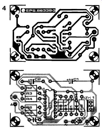
The halogen lamp dimmer is constructed on a printed circuit board as shown in Fig. 4. When the lamp power is greater than 15 W, the triac should be fitted onto a heatsink, and the tracks to the al and a2 terminals should either be covered with solder, or strengthened with short lengths of wire.
172 MODEL AIRCRAFT MONITOR
Older, i.e., not using a computer, radio controlled model aircraft are highly vulnerable to breaks in radio communication, which can lead to a crash or the model landing out of reach, or both. Owing to the allocated radio frequency range being usurped by pirates, its is essential for every model flyer to make sure that the channel to be used is free. Even if it is, it is advisable to continue monitoring it.
In combination with a short-wave receiver, the circuit presented here enables monitoring the 27 MHz radio control band. The aerial signal is filtered (26 . . 41 MHz) and applied to the input of differential amplifier T1-T2. Since the current source of this stage consists of an oscillator, the amplifier functions as a mixer. The crystal oscillator can operate with almost any crystal between 2 and 32 MHz.
The output circuit, L4 –C5 –C6, is tuned to about 27.2 MHz. This frequency is inversely proportional to the values of the coil and capacitors.
-----------

The values of the crystals are based on a 40-channel set-up. In switch position A, the circuit functions as an aerial amplifier; in position B, channels 38...49 are converted to 8 . . .19; in position C, channels 50 . 53 are converted to 20 . . 23; and in position D, channels 61 . . . 79 are converted to 21 . . . 39.
The receiver into which the monitor is coupled need not be suitable for FM reception: an AM receiver can work on FM by detuning the monitor a few kHz.
173 MODEL RAILWAY MONITOR PANEL
--------
---------
Many railway modelers would love to have a track monitor panel, but, unfortunately, the few commercially available types do not justify their cost. It is, however, not too difficult to make one yourself.
The reproducing of the track diagram and the mounting of the monitor lights on the panel can be accomplished without too much trouble. There is a problem, however, in indicating the position of turn outs and color-light signals, because these elements are normally operated by spring-loaded switches to prevent the burning out of the solenoids. After the push-button on the control panel has been released, the supply line is no longer live and can, therefore, not be used for lighting an indicator. This problem can, fortunately, be solved by a couple of R-S bistables (NOR gate latches).
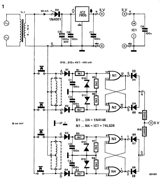
The push-button switches and solenoid coils shown in figure 1 are those already contained in the railway set-up. Note that the system is assumed to operate from a 9 . . .15 V AC supply.
Parts list:
Resistors:
R4 = 4k7
R5 ... R8 = 2k2
R9, R10 = 330 ohm
Capacitors:
C1 ... C4, C6...C8 = 100 n
C5 = 220 µ/40 V
Semiconductors:
D1 ...D4 = 1N4148
D5 . . . D8 = LED (red or green, as required)
Do = 1N4001
D10 .. .D13 = zener diode, 4V7/400 mW
= 74LS28 IC2 = 7805
Miscellaneous:
Tr1 = mains transformer, 9...15 V secondary (if not already available from the existing system)
PCB 85493
Each signal normally requires three lines: one for each of the two coils and a common line. Terminals A, B, C, and D in figure 1 are connected to the relevant outputs of the control panel. The circuit as shown is suitable for monitoring two turnouts or two color-light signals via A-B and C-D respectively, but can be extended as required.
The voltages used to energize the coils are rectified and applied to an R-S bistable. This NOR gate latch is set or reset, depending on the nature of the input signal, and this causes the relevant LED to light. If, for instance, pin 8 of N2 is high, pin 10 of this gate is low, and D6 lights.
The circuit as shown has a current consumption of about 30 mA per R-S bistable branch.
Not all monitor LEDs will correctly show the position of the relevant turnout or light signal immediately upon switching on the supply. Briefly pressing one of the two push-buttons of each turnout or light signal will correct this situation.
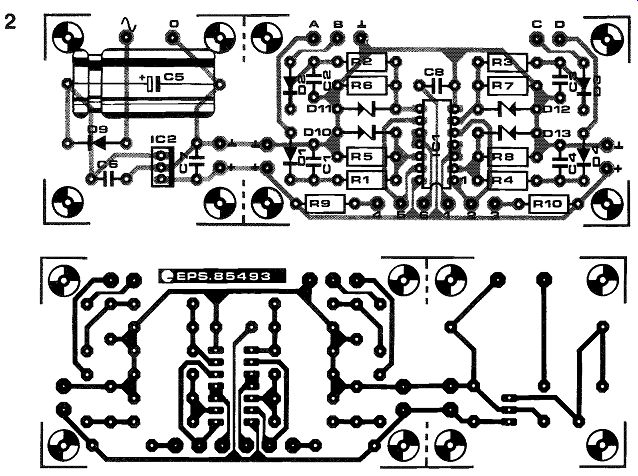
The circuit is most conveniently built on the printed circuit board shown in figure 2. This board can accommodate two monitor channels as shown in figure 1. If more are required, these can be built on additional PCBs. The section containing C5, IC2 and D9 may be cut off subsequent boards, but if many additional PCBs are used, make sure that the power requirements are still met! The + 5 V and 0 V terminals on all boards should be interconnected.
174 "ON THE AIR " INDICATOR
In radio and television studios it is customary to indicate to all concerned when the microphone or camera is "on the air". This is normally done with a red light at or near the relevant camera or micro phone. The circuit described here is intended as an auxiliary for a DIY mixer unit.
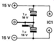
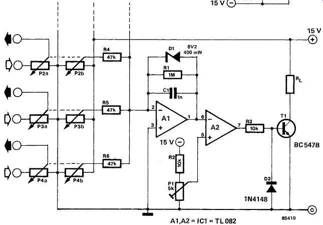
To make the circuit automatic in action, stereo slide potentiometers are used at the audio inputs. When one section of these potentiometers is connected to the +15 V line, the potential at the wiper of this section is a measure of the potentiometer setting.
This potential is amplified in opamp A, and applied to the inverting input of A2. The latter opamp toggles as soon as the level at its inverting input exceeds that at its + input, which has been set with preset Pt.
----------
The slide potentiometers for this purpose are always logarithmic types, so that the voltage rise at the be ginning of their travel is always pretty small. To en sure correct operation of the circuit even at these settings of the potentiometers, the gain of A1 has been arranged fairly high, about 26 dB.
Opamp A1 also serves as a summing amplifier that monitors a row of audio inputs. If it is required that each audio input has its own monitor, the two opamps must be repeated for each input, but P of course, continues to provide the non-inverting potential for all opamps in the A2 position.
The output of the indicator is provided by a type BC 547B transistor, which can switch up to 100 mA. This current is sufficient to light a signal lamp or light-emitting diode (LED) with bias resistor, or to drive a relay.
Current consumption with the BC 547B off amounts to not more than 10 mA.
If low-resistance stereo potentiometers are used, the direct current through the "indicator section" may be too high; if that is so, it is advisable to use a drop ping resistor in series with the section.
175 PWM DRIVER FOR DC MOTORS
-------
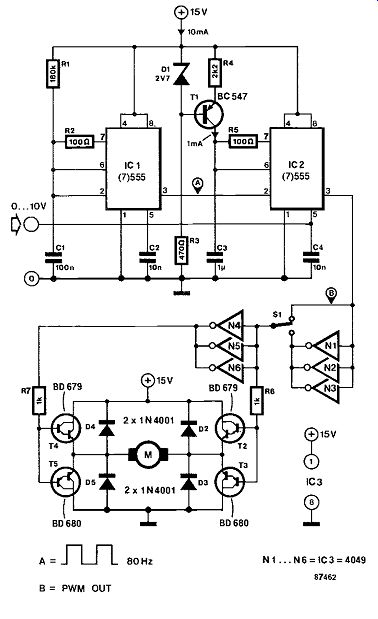
The speed of DC motors is relatively simple to control. For independently energized motors, the speed is, in principle, a linear function of the supply voltage. Motors with a permanent magnet are a sub category of independently energized motors, and they are often used in toys and models. In this circuit, the motor supply voltage is carried by means of pulse width modulation (PWM), which ensures good efficiency as well as a relatively high torque at low motor speeds.
A single control voltage between 0 and +10 V enables the motor speed to be reversed and varied from 0 to maximum in both directions.
Astable multivibrator IC1 is set up as an 80 Hz oscillator, and determines the frequency of the PWM signal. Current source T1 charges C3. The sawtooth voltage across this capacitor is compared with the control voltage in IC2, which outputs the PWM signal to buffer N1-N3 or N4-N6. The darlington-based motor driver is a bridge circuit capable of driving loads up to 4 A, provided the run-in current stays below 6 A, and sufficient cooling is provided for the power transistors T2-T5.
Diodes D2-D5 afford protection against inductive surges from the motor winding. Switch S1 makes it possible to reverse the motor direction instantly.
176 SECTION INDICATION FOR MODEL RAILWAY
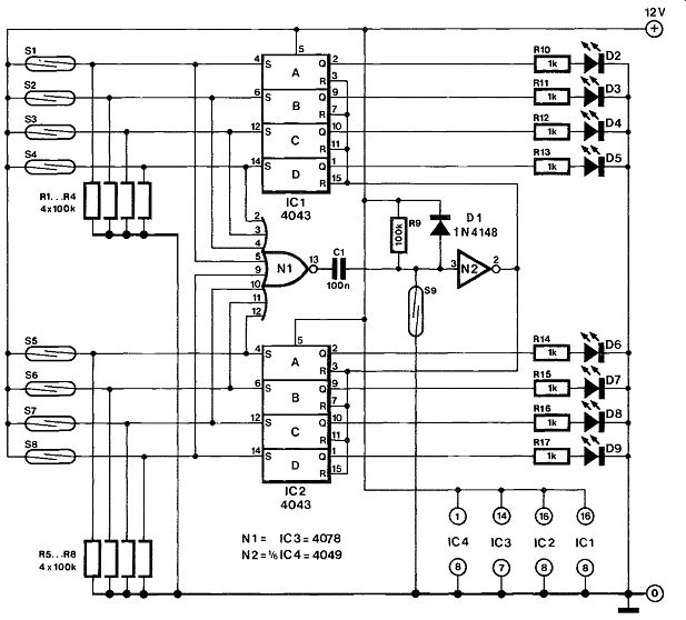
This section indication system may be just the thing you have been looking for when you own a fairly large model railway with tunnels and tracks at several levels, and are sometimes at a loss to find the whereabouts of a particular train. This circuit uses LEDs to indicate the train's position. Each track block is split up into 8 sections, whose starting points are marked with reed contacts (S1-S8). A ninth reed contact is fitted at the end of the block, to enable turning off the indication for the relevant length of the track.
The circuit is composed of 8 set-reset (S-R) bistables, which drive a LED each. All SET inputs are combined in a NOR gate, N1, which drives a pulse shaper and buffer to reset the bistables with a brief pulse to ensure that only the LED for the last passed track section is lit. The reed contacts are actuated with the aid of a small magnet fitted to the underside of the engine. Depending on the most suitable location of the magnet, the reed contacts are fitted in between the tracks or alongside the left or right hand rail.
Several of these section indication systems may be fitted in series to enable making a control panel with many lights to indicate the train positions.
Observing the direction of travel of the trains, section junctions are fitted with S9 (end of previous section) and S1 (begin of section) located next to each other.
-----------
177 SERVO-ROBOT DRIVER
Over the past few years, robotics and cybernetics have become new fields of interest for many an owner of a personal micro, equipped with the necessary add-on boards to effect peripheral control. However easy it may seem to write robot control programs and to build the associated computer hardware, the construction of accurately operating mechanical parts (or, if you like, limbs) often poses un-surmountable problems, since a miniature set of gears, ball bearings, spindles and cog-wheels are in no way readily made items for those skilled in programming and soldering.
Despite their limitations as to precision of movement, servo-motors used in model aircraft or boat construction may offer an interesting alternative to more complicated mechanical constructions; applications such as robot arms and sorting machines can be made quite easily with the use of cleverly mounted servo-motors.
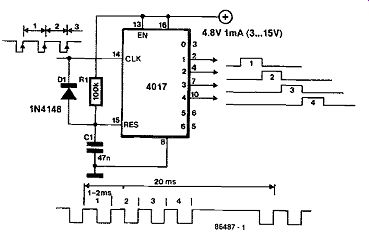
A number of wait loops need to be programmed to supply active low (0) pulses lasting about 0.5 ms, while the interval length between the first and second pulse determines the position of servo 1, while servo 2 is positioned by means of the interval between the second and third pulse, and so 4 on. The repeat rate of the control process should be about 50 Hz (20 ms); see the inset timing diagram.
The synchronization interval is generated with D1–R1-C1, which reset the Type 4017 counter when no negative pulse has been received for about 3 ms.
The control inputs of the servo-motors may be connected direct to the counter outputs.
Finally, interested robot constructors are advised to consult the excellent Robot book, published by W H Smith & Son Ltd, Leicester, under ISBN number 0-7112-0414-4.
----------
178 SOLID-STATE DARK-ROOM LIGHT
Light-emitting diodes are perfectly suitable for dark room light, because they (a) obviate the need of filters; (b) emit cold light; (c) have a life that is not shortened by continuous on-off switching; and (d) do not radiate infra-rays. The types used must, of course, have a high light output; fortunately, there are nowadays LEDs with a luminous intensity of hundreds of milli-candela.
The sensitivity of photographic paper lies between wavelengths 300 nm and about 550 nm, whereas the wavelength of the light emitted by green LEDs is about 565 nm; that by amber types around 585 nm; and that by red LEDs about 640 nm. From this, it is clear that all three types of LED may be used with impunity. None the less, in practice, it is best not to use green ones. Because of the special composition and high sensitivity of color negative paper, only yellow LEDs with reduced light output should be used when processing this paper. The pro posed light, therefore, has provision for reducing the emitted light. Note that since color reversal paper is sensitive to all colors, it can only be processed in total darkness. When working with or thochromatic paper, only red LEDs should be used.
With reference to the diagram, each group of three LEDs is fed from a current source, T1 to T6 respectively. The current level, and consequently the light output of the LEDs, is determined by the setting of Pt Zener diode D19 provides the reference voltage for the current sources, ensuring that the light out put of the lighting unit remains virtually constant over the life of the PP3 battery.
Maximum light output is set with the aid of P2. To this end, both Pi and P2 are first set to maximum resistance; after this, P2 is adjusted until a potential of 0.2 V is measured at point A. The maximum cur- rent through the LEDs is then about 20 mA.
As the photograph shows, the unit has been constructed so that S1 is easily operated. Since this switch is a press-to-make type, the light will switch off as soon as it is put aside, thus preserving the battery. It is possible to have the light on continuously by connecting an external battery to Uext. In that case, R10 must be matched to this source according to R10 = (Uext-9)10 [k-Ohm] but only if NiCd batteries are used. If standard cells are used, D20 and Rio must be omitted.
If a variety of photographic paper is processed, it may be useful to be able to switch between red and amber LEDs. For that purpose, each of the eighteen original yellow LEDs is duplicated by a red LED, shown in dashed lines. Switch S2 may be used to select the relevant bank of LEDs (red or yellow) as required for the specific application.
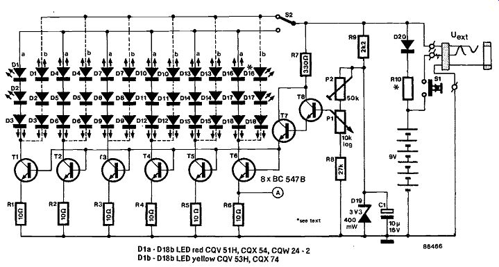
-------------- Dia D18b LED red CQV 51H, CQX 54, COW 24 2 Dib D18b
LED yellow CQV 53H, COX 74
179 SPEED CONTROL FOR R/C MODEL
The speed and direction of rotation of a motor in a radio controlled model airplane or boat is generally controlled by pulse width modulation of the supply voltage to the motor driver stage.
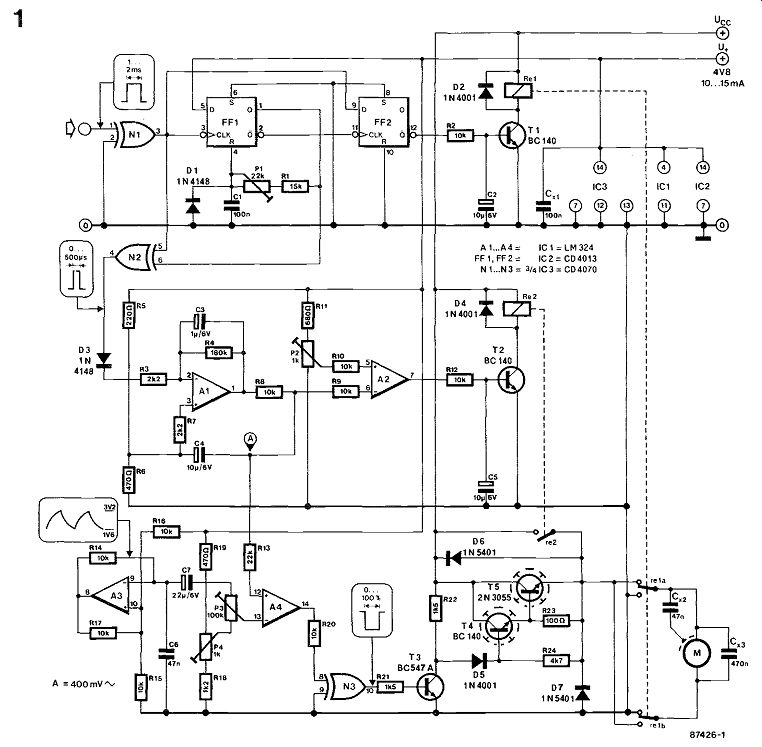
In the present circuit, shown in Fig. 1, bistable FF1 is set up rather unconventionally to function as a monostable multivibrator, whose period is set with this period determines the toggle point at which the motor's direction of rotation is reversed.
Output ohm of FF2 goes high when the pulse at the D input (PWM signal) is shorter than that at the CLK input (signal from FF1). This causes T1 to actuate Re1, so that the motor direction is reversed.
The PWM control signal applied to the circuit is also fed to N2, whose output pulse width is the difference between that of the input signal and that from FF1. The pulse width at the output of N2 therefore decreases as the relevant control handle on the transmitter is moved further towards either extreme, and is maximum when the handle is in the central position. The output of N2 is integrated by A1 to obtain an output voltage proportional to the pulse width. A4 compares this output voltage with the triangular signal at the wiper of P3, so that a variable duty factor signal is obtained for driving the power output stage comprised of T4-T5. Mean while, A2 compares the proportional voltage from A1 to the level set with P2. When the output of A1 is lower than the threshold, i.e., when the motor speed exceeds the preset level, T2 activates Re2. This causes the collector-emitter junction of series regulator T5 to be bypassed by the relay contact, and so enables the motor to run at full speed, because the forward drop across T5 is eliminated.
The frequency of the triangular signal from A3 is of the order of 2 kHz, which is suitable for most motors. Capacitor C6 may be increased to lower the frequency for non-standard motors. Conversely, if the frequency is increased, care should be taken to observe the maximum switching speed of Ts, which is a commonly available, but relatively slow power transistor.

------------
Presets P4 and P3 determine the limits of the in operative range of the handle, and the point that corresponds to maximum motor speed, respectively.
More specifically, P3 sets the amplitude of the triangular signal, while P4 sets the offset level, to enable A4 to output the triangular wave undistorted and with the maximum possible voltage swing.
Preset P2 is used to define the point at which the motor is switched to full speed. Some care should be taken in this setting to allow a sufficiently large control range for the handle, and also to avoid the risk of Reg clattering or being blocked.
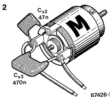
Be sure to fit the 470n capacitor across the motor terminals, and the 47n capacitor between one of these and the motor body-see Fig. 2. The coil voltage of the relays should be equal to the voltage for the battery that powers the motor, while the contacts must be capable of handling the current demand of the motor. Transistors T4 and T5 should be fitted with a heatsink. Note that although the Type 2N3055 can handle currents up to 10 A, it may be a good idea to fit two in parallel with OR1 emitter resistors for equal current distribution when heavy loads are to be controlled. The current rating of D6 and D7 must also be observed: for the stated 1N5401s, Inman = 3 A, and two may have to be connected in parallel when this current is approach ed. Finally, U + is the model's battery voltage (4.8 V), and + Lice is the supply voltage for the motor.
---------------
180 STARTING-PISTOL SIMULATOR
------------
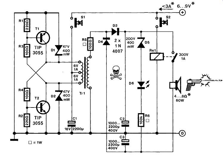
In this circuit, a discarded power loudspeaker serves to simulate the loud bang from a starting-pistol.
Power transistors T1-T2 and mains transformer TRI form a power oscillator, which can be started by pressing S1. Zener diodes D1-D2 protect T1-T2 against inductive voltage surges. The operating frequency of the oscillator depends on the core material of Tri, and the current through its 240 V winding. While S1 is kept actuated, the oscillation frequency is lowered from several kHz to about 50 Hz as the charge voltage across flash capacitors C2- C3 rises. The charge current is limited by R5, while D3-D4 form a voltage doubler, so that several hundred volts are available across the contact of Re1.
LED D6 lights to indicate that the flash capacitors are fully charged, and that S1 may be released.
When the fire button, S2, is pressed, Re, is energized, and a short pulse of 50-100 Ap is passed through the loudspeaker's voice coil. Make sure that this can handle the current surge, on penalty of once and for all destroying the cone suspension.
The current consumption of the starting-pistol simulator is about 3 A immediately after pressing S1, and gradually falls to 0.5-0.8 A when the reservoir capacitors contain their nominal charge. The loudness of the bang can be increased by raising the supply voltage to a maximum of 12 V, provided the loudspeaker can handle a peak power of more than 1,000 W It is recommended to test the circuit at a supply voltage of 3 V. Finally, bear in mind that the generated high voltage is extremely dangerous, and requires due attention to be paid to proper insulation of all components in the high voltage section.
181 TIME-LAPSE UNIT
----------
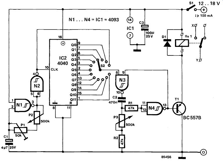
Which amateur film maker has not wished sometime that he could experiment with time exposures? Fortunately, it is now possible with a simple electronic circuit to see the grass grow with out having to sacrifice a night's sleep.
The circuit consists of a clock oscillator, N1-N2, a 12-stage binary counter, IC2, and a monostable, N3-N4. Preset P1 is adjusted to make the highest oscillator frequency about 16 Hz. When switch S2 connects pin 4 of N2 to pin 8 of N3, the circuit works in "real time". Each successive step of S2 from this position doubles the time between exposures. At the minimum oscillator frequency of 0.5 Hz, and S2 connected to the Q11 output of IC2, intervals of up to two hours are possible between exposures.
As the signal at the wiper of S2 is a square wave, which is- by definition- logic 1 for half the time, it is essential that it is shaped in a monostable. The duration of the consequent pulses is determined by Pa Their width should, of course, not exceed the period of the clock oscillator.
Many film cameras are provided with a miniature socket via which they can be operated for single frame exposures and film transport. Contacts X and Y of relay Re, should be connected to this socket via a suitable cable. If you have any trouble with this, or are not sure of the socket connections, it is best to seek advice from your local photographic dealers.
182 TIMER FOR FIXING BATH
-------------
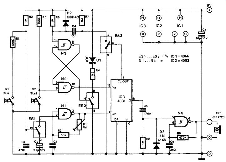
When, after developing, photographs are immersed in the fixing bath at irregular intervals, it becomes difficult to observe the correct fixing time for each of these. This problem is solved by the present timer, which is capable of "remembering" up to 32 immersion times, and automatically provides a signal when a photograph is to be taken out of the bath.
Any time a photograph is immersed in the fixer, the user presses the start key on the timer, which responds by lighting a LED. When the fixing interval has lapsed, the timer provides a short beep.
The circuit is composed of a 64-stage shift register which is loaded with zeroes on power up, because it lacks a reset input. Electronic switch ES, connects the frequency determining capacitor to the in put of clock oscillator N1 . The logic level that exists at the Dm terminal of IC3 is shifted towards output ohm at a speed that is defined by P1 , which enables defining fixing times between roughly 1 and 10 minutes, 9 minutes being a commonly used value.
When the START button is pressed, S-R (set-reset) bistable N2-N3 toggles, and LED D1 lights. A logic 1 is written into the shift register with the aid of a positive pulse transition applied to terminal CP.
After 64 clock pulses from N1 , the logic high level is available at the output of the shift register, and enables oscillator N4 to drive piezoelectric buzzer. The LED is turned off shortly after the START button is pressed, because the bistable is reset by the CL. OUT pulse from IC3.
The timer is conveniently fed from a 9 V battery, and should not consume more than about 10 mA.
---------