Last month we looked at many kinds of capacitor. This month we cover the group known as electrolytic capacitors, which pack high values of capacitance into a small space.
By Nicholas Bellenburg
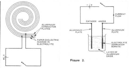
Figure 1. Making an electrolytic capacitor: a layer of aluminum oxide is formed on the plates by electrolysis. This acts as a strong dielectric.
Fig. 2 .... electrolysis: putting a current through the electrolyte causes aluminum oxide to form on the anode plate.
LAST MONTH we looked at the many different types of non electrolytic capacitors available; this time it is the turn of electrolytic and variable types.
Electrolytic capacitors enable us to use large values of capacitance and voltage, yet keeping the physical volume of the components themselves relatively small. So called 'ordinary' foil type electrolytic capacitors have two sheets of aluminum foil wound in a spiral, like the non electrolytic types we've already seen. The difference here though is that the paper dielectric which separates the conductive plates is impregnated with an electrolyte (Figure 1).
Through the chemical process of electrolysis--like that which occurs in a battery or an electroplating works--the electrolyte causes a thin film (about 10^-4 mm in depth) of aluminum oxide to be deposited on one of the aluminum foils.
This process is known as forming (Figure 2), and the oxide layer acts as an electrically strong dielectric. That's to say that it can resist very high voltages in relation to its thickness.
Figure 3a shows an electrolytic capacitor with an impregnated paper dielectric cut in two. Figure 3b shows the same component with part of the roll or conductors and dielectrics unrolled.
You can see from these photographs that the capacitor's outer aluminum can has a crease or band around one end.
This is to indicate the positive pole of the capacitor. The capacitor has a positive pole because during the forming process the oxide layer is only deposited on the anode--the plate that was connected to the positive side of the power source used. From this point on the electrolytic capacitor has to be connected in circuits the correct way round. The positive terminal (anode) goes to the positive side of the circuit, negative terminal (cathode) to the negative voltage.
If the capacitor is connected the wrong way round, the dielectric film can break down and in some cases the whole device can explode quite loudly.
This explosion is caused by a gas being given off by the electrolyte, which causes pressure to build up eventually rupturing the component's can or in some cases blowing the end off.
Polarization
Electrolytic capacitors are thus said to be polarised. Large alternating voltages must of course never be applied to electrolytic capacitors, although variable voltages are permissible as long as the positive lead of the component is not subjected to negative potentials.
As well as being able to withstand relatively high voltages, electrolytic capacitors also have the advantage of being self healing if the dielectric oxide layer is broken by a voltage surge or dielectric weakness (when they are correctly connected). This is because after the voltage overload is removed, the action of electrolysis will occur again and reconstruct the oxide layer.
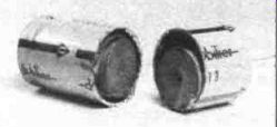
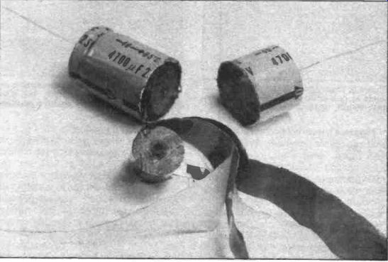
Figure 3. (a) shows a paper electrolytic cut in half: (b) shows the same capacitor with the roll of dielectrics and conductors partially unrolled.
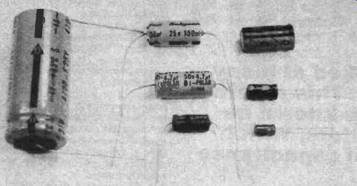
Figure 4. 4. A selection of common electro values: from left to right and
top to bottom: 4700, 25V; 150u F, 25V; 100uF, 63V; 4u7, 50V; 100uF, 10V; 1uF,
63V; 0 ul, 50V (slightly larger than life size).
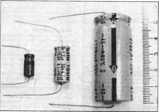
Figure 5. Three axial electrolytics (ie with a lead at either end): left to
right, 1uF, 63V; 4u7, 50V and 4700uF, 25V.
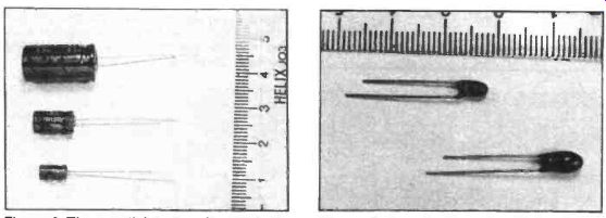
Figure 6. Three radial devices (ie with both leads at one end): top to bottom,
100uF, 10V; 100uF, 10V and Out, 50V.
Figure 7. Two tantalum bead capacitors; above, 0 uF, 35V; below, 10 uF, 16V. The long lead indicates the positive connection.
Figure 4 shows a selection of electrolytic capacitors commonly available. As you can see, many different permutations of capacitance, voltage rating and size can be obtained. You'll also have noted that there are two different ways in which the connecting leads are attached to the capacitors.
The components with a connecting lead at each end are known as axial devices, while the capacitors that have both leads coming from the same end are called radial components.
Figure 5 shows axial devices (from left to right) with values of (i) 1 uF rated at 63V, (ii) 4uF7 rated at 50V and (iii) 4700uF rated at 25V. Figure 6 shows radial devices (from top to bottom) with values of (i) 100uF rated at 63V, (ii) 100uF rated at 10V and (iii) 0 uF1 rated at 50V. As you can see, in comparison with the non electrolytic types we looked at last month electrolytic capacitors are substantially smaller for the same rated values. The cost of the components shown is from around 10p to £ (x 1.4 USD) 1.00 each.
The capacitors shown are helped, in their quest for small volume, by an etching technique that is applied to the foil plates. Etching the plates roughens their surfaces and so increases the surface area. This means that the overall dimensions of a given foil can be made smaller than they would be if it was perfectly smooth.
One disadvantage of electrolytic capacitors, though, is that they have a very wide tolerance: typically ±20% or-10+50%. In other words, the actual capacitances of components can be quite a great deal different to the rated values. This also means that when an electrolytic capacitor is chosen for a circuit, those available from a typical supplier's catalogue should always be able to fit the bill. In this case the nearest capacitance to the one needed, and the equal or next largest voltage should be chosen. So, suppose a circuit that you have design calls for a 70uF capacitor rated at 10V. Looking at a supplier's list the actual capacitor to choose would be the 60uF 16V one.
Other Types
Figure 7 shows two, tiny, tantalum bead electrolytic capacitors. The one at the top has a value of OuF1 rated at 35V, while the bottom one has a value of 10uF rated at 16V. The long lead on these capacitors indicates the positive connection.
Tantalum is a metal of very high purity and its oxidization by electrolysis means that tantalum capacitors work in a very similar manner to aluminum foil types.
Figure 8 shows a schematic diagram of a tantalum electrolytic capacitor. As you can see the electrolyte is manganese oxide.
These components have the advantage of providing high values of capacitance in very small packages.
However, working voltages are limited to around 35V. The tolerance of tantalum bead capacitors is typically ±20% and values from 0uF1 to 100uF are available.
Prices are around 20p each.
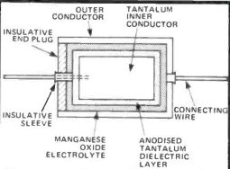
Figure 8. A schematic of a tantalum bead capacitor: the electrolyte is manganese
dioxide.
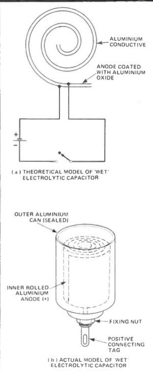
Figure 9. (a) a theoretical and (b) an actual representation of a 'wet' capacitor.
No paper is used; the rolled aluminum oxide is oxidized on one side, forming
the anode (-), while the sealed can, filled with the electrolyte, acts as the
cathode (-). The nut provides a negative connection to the chassis.
The tantalum capacitor that we just looked at used manganese oxide as an electrolyte. Aluminum types also exist that use just an electrolyte, with no tissue paper layers for it to soak in. These are called 'wet' capacitors and Figure 9 shows such a device in theoretical form (a) and actual form (b). Here the inner rolled up aluminum foil is oxidized by the electrolyte and as such is the anode (positive) plate.
The aluminum can in which this is contained acts as the cathode (negative) plate and is filled with the electrolyte. The positive connection comes through an insulator in the can's bottom, while the fixing nut on the bottom of the can provides the negative connection. These electrolytics are usually quite bulky (typically 100mm high and 35mm in diameter) and are usually used to 'smooth' power supplies and as such have very high voltage and capacitance ratings. Tolerances typically run at +80%-20% and on average, capacitors of this type cost from £ (x 1.4 USD) 3.50 to £ (x 1.4 USD) 11.00 depending on rated value.
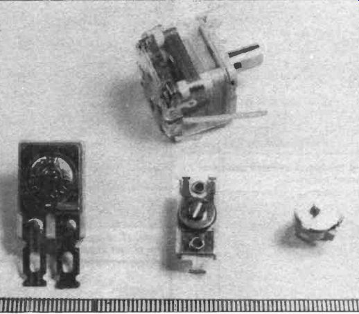
Figure 10. Variable capacitors: left to right, a multi plate compression trimmer
(preset); a radio tuning capacitor; a 'postage stamp' type compression trimmer
(preset); a vaned miniature trimmer (preset).
Generally speaking, therefore, electrolytic capacitors give us high capacitance and voltage values in physically small packages. On the debit side, though, they have a very wide tolerance range, must only be used with DC supplies, and have a tendency for the electrolyte to dry out in high temperatures, affecting their action adversely.
Variable Capacitors
Variable capacitors are non-electrolytic and take two forms: preset and manually variable. Figure 10 shows a selection.
Manually variable capacitors are commonly used in the tuning sections of radios. As we know, capacitance can be varied by altering the overlapping area of the two plates or by altering the thickness of the dielectric between them.
Manually variable capacitors work by varying the area of overlapping plates.
Figure 11 shows the way in which this happens. One of two semicircular plates is fixed to the central spindle. Rotating the spindle moves the one plate over the other.
In reality, more than two plates-known as vanes--are used, as Figure 12 indicates. This is a dual ganged variable capacitor, which means that the front and back sections are separate, so that they can be used for, say, different wavebands of a radio. The front section of this one is variable from 10 to 208pF while the rear section goes from 8pF5 to 176pF. A variable capacitor like this costs about £ (x 1.4 USD) 9.00, and would be used in hi-fi tuners and high quality radios.
A rather cheaper variable capacitor is shown in Figure 13. The body of this component is only 20mm long and it is designed for direct printed circuit board mounting. This miniature capacitor has four tuning sections--two for AM and two for FM. There is also a preset trimmer (which we shall look at next) for each section--shown in Figure 14.
This variable capacitor is intended for use in cheaper transistor radios and is priced at about £ (x 1.4 USD) 1.75.
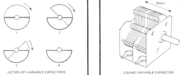
Figure 11. Adjusting a vaned capacitor: as the area of overlap increases,
so the capacitance varies from 0 to maximum.
Figure 12. A dual-ganged variable capacitor, with two controls and multiple plates.
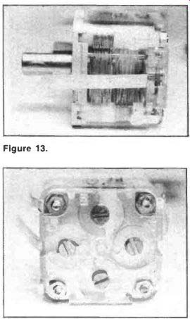
Figure 13. A miniature variable capacitor has four tuning sections.
Figure 14. The rear of the capacitor shows in Figure 13. showing four preset trimmer capacitors as part of the unit.
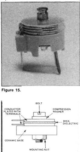
Figure 15. A close up view of a movable vane preset capacitor.
Figure 16. The construction of a compression preset trimmer.
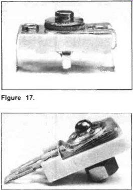
Figure 17. A closeup of the capacitor shown in Figure 16.
Figure 18. A preset trimmer with six conductive plates.
The preset trimmer capacitors shown on the bottom of the variable capacitor in Figure 14 use overlapping vanes which may be tuned by the screws, allowing you to fine-tune the radio's overall tuning range.
Preset capacitors are used for other applications too, and can be either the movable vane type or what are known as compression trimmers. A movable vane type can be seen in Figures 10 and 15. It is only 9mm in diameter and is available in maximum capacitances of 10pF, 22pF and 65pF for about 25p.
Compression trimmers work by altering the thickness of the dielectric between the conductive plates by compressing it to different depths.
Figure 16 illustrates the make up of such a preset capacitor and Figure 17 shows an actual component. This is about 20mm long and uses a mica sheet as the dielectric. The capacitance is variable from 3pF to 40pF and it costs around 30p.
Figure 18 on the other hand shows a preset trimmer capacitor with more than two conductive plates. It has six in fact, three connected to each terminal. Mica dielectrics are also employed. The capacitance of this component varies from 100pF to 500pF. The device itself is 34mm long overall and costs about 40p.
To Sum Up
Between the last Components From The Inside Out and this one, we have looked at most of the types of capacitor that are commonly available. Let's end our discourse by looking at the various attributes of the different types, as shown in Table 1.
-----------------
Table 1 Attributes and applications of different capacitors
Type Properties Paper Cheap, general purpose capacitors with a reasonable capacitance to size ratio.
Plastic:
Polystyrene High insulation resistance; low losses; small.
Polycarbonate Miniature self healing.
Ceramic:
Low permittivity Medium permittivity High permittivity Low dissipation High capacitance to size ratio.
Large capacitance to size ratio; voltage and temperature sensitive.
Mica Highly stable, low dissipation
Electrolytic:
Aluminum Polarised devices; very large capacitance to size ratio.
limited lift and temperature range.
Tantalum Small, expensive, polarized, highly reliable.
Variable:
Manual Variable within certain limits.
Applications General purpose.
General purpose and charge storage; Filters.
Miniature general purpose.
Low voltage applications Temperature correction components General purpose.
Smoothing circuits: General purpose.
Where reliability and/or size is a priority.
Tuning circuits.
Preset Variable within certain limits. Tuning circuits
-------------------
Also see: SECRETS OF SOLDERING