Here's a DC power supply that makes working on high voltage projects a breeze.
By DAVID CUTHBERT

A VARIABLE HIGH-VOLTAGE POWER supply can be a great convenience to have on the bench.
You can use it for servicing tube-type equipment, checking capacitors, and for general experimentation. This article describes the construction of a 0 to 250-volt, 100-milliamp regulated power supply. The supply is short-circuit protected and has an output impedance of 15 ohms. Output noise is less than 20 millivolts rms, while the temperature coefficient is only 0.03 percent per degree Celsius.
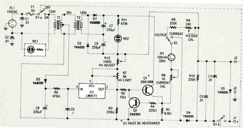
FIG. 1--HIGH-VOLTAGE DC SUPPLY. The circuit uses two transformers
to develop 300volts DC.
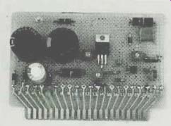
FIG. 2--MOST OF THE CIRCUITRY is contained on a 44-pin edge connector-perforated
construction board.
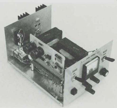
FIG. 3--PROTOTYPE POWER SUPPLY. Everything fits neatly in the metal
cabinet that measures 8 x 6 x 5 inches.
Operation
The circuit, shown in Fig. 1, uses two standard filament transformers to develop 300 volts DC. Transformer T1 steps down the 120-volt AC line power to 25 volts, and T2 steps the voltage back up to 120 volts. The 120-volt output of T2 feeds the full-wave doubler consisting of C7, C8, D1, and D2. Neon lamp NE2 and R11 form a combination bleeder and high-voltage warning light.
The heart of the circuit is IC1, an LM317T regulator. The regulator is powered by 16 volts derived from the secondary of T1.
Resistor R5 limits the current to IC1 during short-circuit operation. Current flowing through HV ADJUST potentiometer R12 generates a 1.25-volt drop across R7. If the power supply output voltage drops, IC1 turns Q1 on harder and raises the supply voltage. Resistor R3 improves the regulation by maintaining a minimum of 3 milliamps through IC1, and R2 is a parasitic oscillation suppressor for Q1.
Components
R1, R4, and Q2 form the current-limit circuit, which works as follows: When 100 milliamps flows through R1, the resulting 0.7-volt drop turns Q2 on, which then steals the base drive to Q1 and limits the supply current. A 1milliamp analog meter is used to read 250 volts or 100 milliamps full-scale. When reading voltage, the meter is connected between the emitter of Q1 and the negative output terminal through R6, R8, and R9. When reading current, meter M1 is connected across current-sense resistor R1 through calibration trimmer R6. Diode D4 protects the supply against reverse current from the load. Switch S1-a turns power on and off, and S1b disconnects the output when the supply is switched off.
Construction
No PC board was used to build the prototype power supply. Instead, most of the power supply circuitry is contained on a 44-pin edge connector perforated construction board (see Fig. 2), which plugs into a matching edge connector that is mounted to the bottom of the cabinet with a couple of standoffs. The plug-in board makes the supply easier to build and to service, if that becomes necessary, in the future. However, the power-supply construction is not critical to its operation.
Power transistor Q1 must be heatsinked. The heatsink for Q1 measures 3 x 3 inches square with 1-inch cooling fins, and is mounted on the outside rear panel of the metal cabinet, which measures 8 x 6 x 5 inches. The case of Q1 can be more than 400 volts above ground, so make sure you mount it with sufficient insulation and put an insulating cover over Q1 to prevent a shock hazard. The fuse holder is mounted on the rear panel.
Switches S1 (PowER) and S2 (METER), which must both be rated for 250 volts AC, are mounted on the front panel of the cabinet, along with the meter (M1), Hv ADJUST potentiometer R12, output jacks J1-J3, and neon indicator NE1. Diode D5 is soldered directly across jacks J1 and J2.
Figure 3 shows an internal view of the prototype.
Calibration
During calibration, be very careful, as 300 volts will give you quite a shock! Set your DVM to the highest DC voltage range, and connect it to the power supply outputs. Switch the supply on, and turn the HVADJUST knob to maximum. Adjust t-IV LIMIT R7 for 260 volts. Switch the supply off, and set the DVM to the 200 milliamp range. Switch the supply on, and turn the Hv ADJUST knob to maximum. The supply should limit at about 100 milliamps. Adjust the current meter calibration trimmer R6 so the current meter agrees with the DVM. Switch the DVM back to the voltage range and adjust the xv ADJUST knob for 250 volts. Adjust the voltmeter calibration trimmer R8 so the meter reads full scale.
Although the outputs can "float," it's best to connect one of them to the ground jack. Due to the voltage rating of typical potentiometers we do not advise floating the output more than 150 volts above ground.
PARTS LIST
All resistors are 1/4-watt, 5%, unless otherwise noted.
R1-6.8 ohms
R2-10 ohms
R3, R4-220 ohms
R5-470 ohms, 1-watt
R6-1000-ohms, potentiometer
R7 5000-ohms, potentiometer
R8 50,000-ohms, potentiometer
R9, R10 220,000 ohms, 1-watt
R11 470,000 ohms
R12-1 megohm, panel-mount potentiometer
Capacitors
C1-C4-0.01 uF, 500 volts, ceramic disk
C5-0.1 uF, ceramic disk
C6-220 µF, 25 volts, electrolytic
C7, C8-220 uF, 200 volts, electrolytic
Semiconductors
IC1--LM317T variable positive regulator
D1--D51N4005 diode (600V, 1A)
Q1--2SC1308 NPN high-voltage transistor, TO-3 type (Radio Shack #276-2055)
Q2--2N3904 NPN transistor
Other components
T1, T2--120/25.2 volt center tapped 2-amp power transformer
J1 banana jack, red
J2 banana jack, black
J3 banana jack, green
F1-1/2-amp slow-blow fuse
S1, S2-DPDT switch, (6A, 250VAC)
M1-1 milliamp panel-mount DC meter
NE1-neon indicator lamp with built-in series resistor
NE2-neon lamp
Miscellaneous: Fuse holder, edge-mount perforated construction board and matching edge connector (optional, see text), enclosure, heatsink, TO-3 mounting hardware for Q1, standoffs, knob for R12, wire, solder, etc.
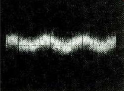
FIG. 4--THERE IS ONLY 20 MILLIVOLTS of ripple in the 250-volt DC output.
------------------
Also see: Triple Output DC Power Supply