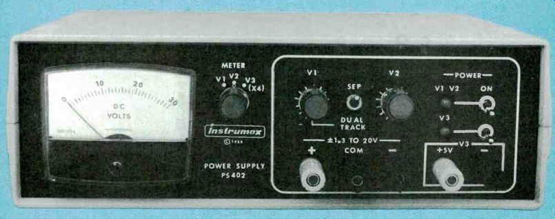
Build a triple-output power supply-a power source you'll find quite useful around the home and shop.
By JOHN F. KEIDEL
A DC POWER SUPPLY IS REQUIRED for nearly all electronic circuits. Some circuits are passive and don't need a power supply, and others draw power from some other source. However, all stand-alone active circuits need a power supply. It is difficult to find an off-the-shelf benchtop power supply that's both versatile and inexpensive--that's why you want to build it yourself. If you are looking for a multiple-output, bench-type power supply, look no further.
The power supply in this article features metered voltages on all sources, vernier controls (based on 10-turn potentiometers) on its plus and minus 1.3- to 20-volt outputs, and separate adjustments or dual-tracking operation for those same supplies. It also has a precise, fixed 5-volt logic supply that's completely independent of the variable supplies.
This triple-output power supply boasts exceptional line regulation: less than 1 millivolt output change for a 10% change in line voltage. Ripple and noise figures are less than 1 millivolt peak-to-peak at full-load. The maximum current available at each of the variable outputs is 200 milliamperes, and the fixed 5-volt supply can output 300 milliamperes.
Design considerations
Preregulator circuits precede the output regulators on all three supplies. The pre-regulators dissipate heat and maintain the voltage across the output regulators at a constant 3 volts. Also, a 30- to 40-milliampere thermal-stabilizing current is drawn by all supplies.
That improves load regulation, and keeps the voltage-reference element contained within each output regulator at a constant temperature. The normally high heat dissipation of the regulators is greatly reduced by the pre regulators.
Circuit operation
Figure 1 is the schematic of the positive and negative variable supplies; look at the positive supply. Tracking preregulator IC1, an LM317T, maintains a constant 3-volt drop across output regulator IC2. The pre-regulator works as follows: Resistor R1 in conjunction with IC1's internal reference voltage (1.25 volts) causes a specific current to flow through R2 which, in turn, drops 1.7 volts across it.
Those two voltages added together equal approximately 3 volts, which always appears across IC2.
Regulator IC2 establishes a programming current (1.25 volts divided by R3) that flows through front-panel control R18 (a 10-turn potentiometer), which thereby sets a positive output voltage equal to the adjustable drop across R18 plus the 1.25-volt reference. Resistor R4 provides the thermal-stabilizing current that was previously explained.
Capacitor C4 improves output ripple rejection. Capacitors C2, C3, and C5 bypass and stabilize their respective regulators by preventing spurious oscillations.
Regulator IC2 is protected from capacitive discharges caused by short circuits external to the supply. Diode D2 prevents C4 from discharging through IC2 by providing an alternate path.
Dual tracking keeps the positive and negative variable outputs at the same voltage level, but with opposite polarities. The dual-tracking function is made possible by IC5, a TL071 JFET op-amp configured as an inverting amplifier. In that configuration, IC5 tries to adjust its output so that both input voltages are equal. Since pin 3 of IC5 is tied to ground, it will therefore adjust its output in an attempt to make pin 2 equal to 0 volts.
Note that regulator IC4 is contained within the negative feedback loop of IC5 when S3 is in the DUAL. TRACK position. Resistor R20 is the input to the IC5 inverting amplifier and R21 is its feedback resistor. Set up that way, IC4 automatically adjusts its output so that the voltage at the R20-R21 junction (pin 2 of IC5) is at 0 volts, thus matching the voltage at pin 3 of IC5. Because the value of R20 is equal to R21, and because the voltage at pin 2 of IC5 should equal 0 volts. IC4's output must match IC2's output. but with opposite polarity.
In the dual-tracking mode, R18 controls both output voltages. When switch S3 is in the SEPARATE position, R19 controls the negative voltage output while R18 still controls the positive output.
Because the circuit arrangement and operation of both the negative variable supply and the 5-volt logic supply shown in Fig. 2 are virtually the same as those for the positive supply. operating details of those two supplies will not be given. Note, however, that the 5-volt supply has a different ground (and ground symbol on the schematic) than the variable supplies.
Figure 3 shows the meter circuit. Switch S4 selects the output voltage to be displayed on the meter, and also handles the polarity and switches in the appropriate multiplier resistor (R24 to R26). Resistor R23 compensates for variations in different meters. Note that the ground connections for the bipolar supply and the logic supply are independent of each other, so unlike symbols are used in Fig. 3.
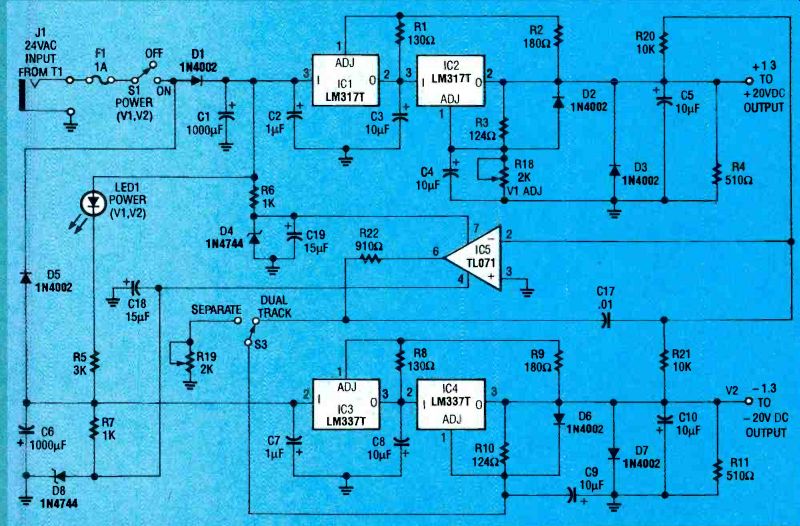
FIG. 1-SCHEMATIC DIAGRAM of variable bipolar 20-volt supplies. Switch S3
controls the dual-tracking option.
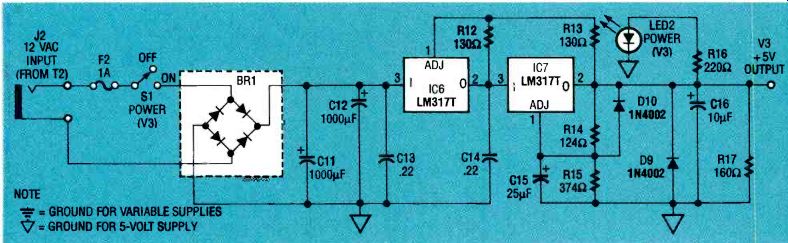
FIG. 2--FIVE-VOLT SUPPLY. The operation of this circuit is similar to the
variable supplies, although it has a separate ground.
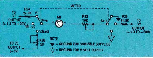
FIG. 3--METER CIRCUIT. This circuit allows the meter to display the output
voltage.
Construction
A PC board is strongly recommended for the assembly of the power supply. You can make your own board using the foil pattern provided here, or order one from the source given in the Parts List. Mount all components as shown in parts placement diagram Fig. 4. Check to see that all diodes, the bridge rectifier, and electrolytic and tantalum capacitors are positioned with the proper polarity before soldering them. A socket is recommended for IC5.
If the PC board is mounted in the recommended case, mounting bosses are provided as an integral part of the case. However, if you use a metal case rather than a plastic one, make sure the heatsinks don't touch the metal side panel. Similarly, ...
----------------
PARTS LIST
All resistors are 1/4-watt, 5%, unless otherwise indicated.
R1, R8, R12, R13-130 ohms
R2. R9-180 ohms
R3, R10, R14-124 ohms, 1 %, metal film
R4, R11-510 ohms, 2 watts R5-3000 ohms, 2 watts
R6, R7-1000 ohms, 2 watts
R15-374 ohms, 1 %, metal film
R16-220 ohms R17-160 ohms, 1/2 watt
R18, R19--2000 ohms, 10-turn cabinet-mounted potentiometer (Digi-Key 73JB202-ND or equivalent)
R20, R21--10,000 ohms, 1%, metal film R22-910 ohms R23-10,000 ohms, PC-mount potentiometer R24, R2 524,900 ohms, 1%, metal film R26-5,000 ohms, PC-mount potentiometer
Capacitors
C1, C6-1000 µF, 50 volts, electrolytic
C2, C7-1 1 F, 50 volts, tantalum
C3-05, C8-C10, C16-10 µF, 35 volts, tantalum
C15-25 uF, 25 volts, tantalum
C11, C12, 1000 RF, 25 volts, electrolytic
C13, C14-0.22 µF, 50 volts, ceramic disc
C17-0.01 µF, 50 volts, ceramic disc
C18, C19-15 RF, 35 volts, tantalum
Semiconductors
IC1, IC2, IC6, IC7 LM317T adjustable positive regulator Motorola or equivalent IC3, IC4 LM337T adjustable negative regulator Motorola or equivalent IC5-TL071 JFET-input op-amp D1-D3, D5-D7, D9, D101N4002 diode
D4, D81N4744 15-volt, 1-watt zener diode
LED1, LED2-red panel-mount light-emitting diode
BR1 Bridge rectifier, 1-amp, 50-volt (Digi-Key DB101-ND, or equivalent)
Other components M1-15-volt DC panel-mount meter (Radio Shack 270-1754, see text)
J1, J2 Coaxial power-input jack (Radio Shack 274-1563 or equivalent)
S1, S2-Panel-mount SPST switch
S3-Panel-mount SPDT switch S4
Panel-mount, 2-pole, 3-position rotary switch (Mouser Electronics 10WA155 or equivalent)
F1, F2-1-amp, 120-volt slow-blow fuse
T1-120 to 24 VAC wall transformer with female plug (Jameco Electronics AC2410 or equivalent)
T2-120 to 12 VAC wall transformer with female plug
Miscellaneous: project case (Jam-eco Electronics H2507), five binding posts, three instrument knobs, four 5-watt heat sinks (for IC2, IC4, IC6 and IC7, Digi-Key HS116-ND); two 10-watt heat-sinks (for IC1 and IC3, Digi-Key HS114-ND), one 6-pin IC socket, two fuse holders, two LED sockets, wire, solder, hardware.
Note: The following is available from Instrumex, PO Box 490, Blue Bell, PA 19422: Ready-to-use PC board and silkscreened plastic front panel, both to fit case noted above-$23.00 + $2.00 S &I PA residents include 6% sales tax. Allow-4 weeks for delivery.
--------------
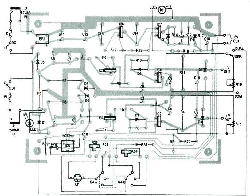
FIG. 4--PARTS PLACEMENT DIAGRAM. Be sure to heatsink the voltage regulators.
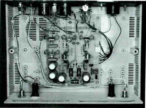
FIG. 5--THE CIRCUITRY IS INSTALLED in a plastic case with slots cut into
the rear panel to allow heat to escape. Power input jacks and fuse holders
are located below the vent slots.
... if the supply is constructed on perforated circuit board, make sure that the heatsinks for the different sources cannot touch one another.
Figure 5 shows the inside of the prototype unit. Notice the wiring arrangement for the back-and front-panel controls.
Power line wires run along the side of the case from their respective fuse holders to power switches S1 and S2, and then they return to input pads on the rear of the PC board.
Use short lengths of 18-AWG copper wire from output pads on the PC board to the binding posts. Be sure to account for all the wiring connections shown in Fig. 4.
Meter M1 can be relabeled to read from 0 to 30 volts, but that task requires a lot of care. Remove the meter's bezel and use white paper correction fluid to cover the original numbers.
Then carefully remove the adhesive backed meter face and apply new numbers (0, 10. 20 and 30) using rub-on transfer numbering.
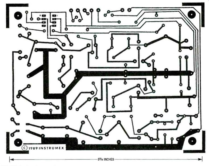
-------------- FOIL PATTERN for the power supply.
When labeled replace the meter face and shift the pointer as required with the zerp adjustment. Avoid touching the fragile meter pointer! The plastic case specified in the Parts List is the recommended choice for the project.
However, holes in the panels can be difficult to drill because the plastic is brittle and is easy to crack. Alternatively, the panels can be made from sturdy 0.1-inch art board (rigid cardboard) purchased from a stationary or art-supply store. All holes can then be made with a hobby knife. You can also buy a silkscreened front panel from the source given in the Parts List.
Venting the cabinet is very important. Two 4-inch slots, 1/2inch wide, were cut in the rear panel to let heat escape. Large rubber feet, although not included with the case, provide that "store-bought" look and prevent the power supply from sliding on the bench.
Calibration Set the meter switch S4 to the V1 position and S3 to the "separate" position. Adjust the output of the positive variable supply to an exact 20 volts with an accurate external voltmeter.
Adjust trimmer potentiometer R23 until the panel meter M1 reads exactly 20 volts. Next, set S4 to the V3 ( x 4) position, and adjust R26 until Ml reads 20 volts (5 volts x 4). An external voltmeter can be used to verify the exact 5.0-volt output.
Using the supply
The variable bipolar and fixed logic power sources are completely independent of one another, so they can even be used to power separate projects. Both sources are also "floating," which permits a variety of configurations. For example, by connecting across the outputs of both variable supplies, a 2.6- to 40-volt output of either polarity, at 200 milliamperes can be obtained. By connecting the fixed logic source in series with the arrangement just described (aiding or opposing), a + 7.6 to + 45-volt or -2.4 to + 35-volt output, respectively, at 200 milliamperes is produced.
When powering op-amps that require equal and opposite voltage sources for + Vcc and -VEE, use the power supply's dual tracking mode. When S3 is set to the "dual" position, potentiometer R18 simultaneously adjusts both variable bipolar sources. Otherwise, leave switch S3 in the "separate" position for independent adjustment.
All outputs are protected against short circuits in the external load by current limiting and thermal overload protective devices, which are built-in features of the voltage-control output regulators.
Any one binding post of a given supply can be connected to the common return of the circuit being powered. Also, that same terminal can be connected to earth ground for optimum safety, if required. Avoid electrically elevating the supplies by connecting them in series with other supplies.
------------------
Also see: COMMON COLLECTOR AMPLIFIERS