By RAY MARSTON
Learn more about resistors--how they are made, and how to apply them effectively in your circuits.
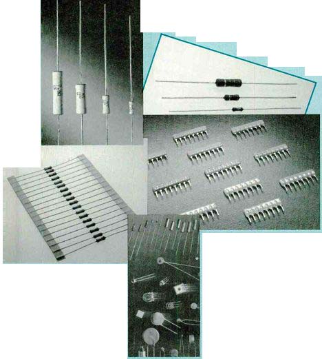
THE DEMAND FOR RESISTORS today directly reflects ongoing changes in the design and packaging of electronic products worldwide. Carbon-film, and metal-film fixed resistors with ratings of 1/4-watt or less have displaced the carbon composition and wirewound resistors so widely specified in the past. The lower power requirements of today's integrated circuits, and the incessant push toward miniaturization have led to wider use of smaller, low cost, low power resistors.
Thick- and thin-film resistive networks permit automated assembly of circuits, particularly digital, where large numbers of resistors of the same value are specified. The chip resistor has moved from its origins in hybrid microcircuits to circuit boards assembled by surface mount technology (SMT). Some other recent trends in resistor specification include: Increased use of fixed resistors and resistor chips with resistive tolerances of ± 1% to ± 5 % in preference to the ±10% to 20% acceptable in the past.
Increased demand for planar chip resistors and networks for automated parts placement, increasing component density while saving PC board space and cutting assembly labor costs.
Trimmer potentiometers made to withstand automated insertion or surface-mount placement, wave soldering, and high-pressure, water-based solvent cleaning.
Decline in the demand for precision potentiometers because of the replacement of analog functions that required precise, repeatable setting with digital circuitry.
Fixed resistors
Every material impedes the flow of electric current to some extent. Materials such as copper or silver offer very little resistance to current flow, and they are called conductors. Other materials such as glass, ceramics, and plastic offer high resistance to current flow, and they are called insulators. Electronic circuits need components with known resistance values in the range between insulators and conductors; those components are called resistors.
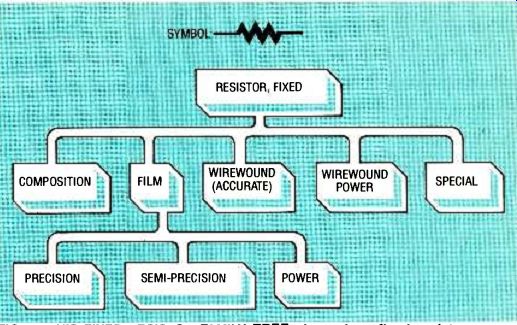
FIG. 1--THIS FIXED-RESISTOR FAMILY TREE shows how fixed resistors are classified
in industry by resistive element and power handling ability.
The unit of resistance is the ohm (represented by the Greek letter omega) Resistance values in thousands of ohms are expressed as kilohms (K or K ohms) and in millions of ohms as megohms (MEG or M ohms). Nominal values of resistors are given at an ambient temperature of 25 °C. The graphical symbol for a fixed resistor is shown at the top of Fig. 1. The block diagram "tree" illustrates how fixed resistors are classified.
The resistance of any resistive material is given by the following equation:
R = p L/A
…where… R = resistance
p = resistivity of the material, ohms-cm.
L = length of material, cm
A = cross-sectional area of material, cm^2
Resistivity p (Greek letter rho) is an inherent property of materials. Values of p for some commonly used materials are summarized in Table 1.
The equation says that for a material with a given resistivity, the resistance varies directly with length L and inversely with cross-sectional area A. For example, a long wire has greater resistance than a short wire, and a thick wire has less resistance than a thin wire.
The voltage and current in a resistor are related by ohm's law:
I= E/R, E= UR, R =E/I … where …
E = voltage across the resistor and I = current flowing in the resistor.
Power P (in watts, W) dissipated in a resistor can be stated with any of the following math expressions: P = EI, = I^2 R, = E^2/R
A number of terms define a resistor in addition to its nominal value in ohms: tolerance, temperature coefficient of resistance, power rating, and rated continuous working voltage.
TABLE 1 RESISTIVITIES OF COMMON MATERIALS
Material p. ohms –centimeter
Silver 1.5 x 10^-6
Copper 1.7 x 10^-6
Aluminum 2.6 x 10^-6
Carbon 30 x 10^-6 to (graphite) 190 x 10^-6
Nichrome 100 x 10^-6
Glass 10^10 10^14
Tolerance expresses the maximum deviation in resistance from the resistor's nominal value, expressed as a percent. General purpose resistors have tolerances of ±5 %, ±10 %, and ±20 %. Most carbon composition and carbon film, and some metal-film and wirewound resistors are in this class. The ± 1% and ±2% semi-precision class includes some metal-film resistors and networks, while the ± 0.5% and 1% precision class includes those with metal film and wirewound elements.
Temperature coefficient of resistance (abbreviated TCR, or tempco) states how the resistor's resistance changes with temperature. TCR is usually expressed as parts per million per degree Celsius (ppm / °C), and can be positive or negative.
Semi-precision and precision units typically have the lowest TCR's.
Power rating is the maximum continuous power, in watts, that a resistor can dissipate at a temperature as high as 70 °C. At temperatures beyond 70 °C, the power rating is reduced or derated. A typical derating curve for a resistor is given in Fig. 2.
Rated continuous working voltage (RCWV) is the maximum voltage that can be applied non-destructively to the resistor.
Noise. Electrons move randomly in all materials and produce random voltages or noise.
Noise in resistors increases with resistance value, operating temperature, and the bandwidth of the circuit in which the resistor is located.
Resistor classification
The blocks in Fig. 1 represent the four most widely specified ...
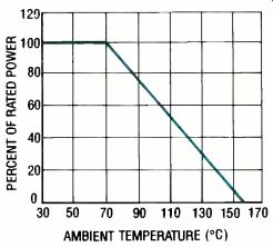
FIG. 2--A TYPICAL RESISTOR DERATING CURVE plots power against ambient temperature,
the temperature of the environment in which the resistor is operating.
... types of fixed resistor-carbon composition, metal-film, carbon-film, and wirewound. The "special" category includes such products as high-voltage resistors, chip resistors, and resistor networks.
Table 2 summarizes the characteristics of the most popular fixed resistors. The values given in this table state the typical extremes for any given resistor, not what is readily available as a commercial product. Manufacturers offer a limited selection of resistors with preferred ratings as standard catalog items.
Thus, it may not be possible to obtain the exact resistor type and value you need off-the-shelf or from the catalog. Resistors with an application specific combination of features can be custom ordered.
The preferred values for all fixed resistors are given later in this article. It is important to keep in mind that for many general applications, more than one resistor type will perform satisfactorily. In those instances, the purchase decision will be based on lowest unit price.
Carbon composition resistors
Carbon-composition resistors were, for many years, the commodity products among fixed resistors. Figure 3-a is a cutaway view of the classical molded carbon-composition resistor. It has a resistance element made by mixing graphite, a form of carbon, with a suitable viscous binder to form a uniform bulk resistive material.
These resistors were made by inserting leads in the resistive element, coating it with an insulating jacket, and molding the unit in a single step before firing it under pressure at a high temperature.
The resistance values of the molded carbon-composition element can be altered by changing the ratio of carbon to binder or the size of the element. Another form of carbon composition resistor that is made by applying a thick film of carbon in a binder on an insulating mandrel was also introduced.
Carbon-composition resistors can have resistance values from about 10 ohms to 22 megohms, and typical tolerances ranging from ±5% to ±20%. Power ratings are 1/8 to 5 watts. Their temperature coefficients are typically greater than 500 ppm/°C. Continuous working voltages can be up to 350 volts. These resistors can absorb moisture in storage or when not operating that will alter their resistance values. They generally recover after operation, because heat drives out the moisture.
Carbon-composition resistors continued in use long after cheaper carbon-film resistors were introduced because of their ability to withstand significant overcurrents without being destroyed.
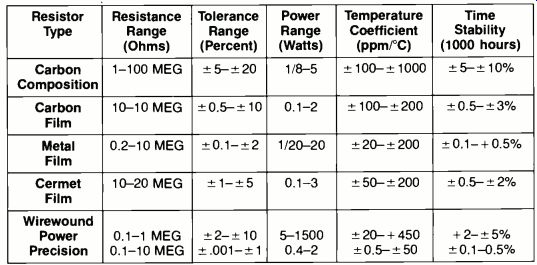
TABLE 2--CHARACTERISTICS OF POPULAR FIXED RESISTORS
Includes general purpose, semi-precision, and precision
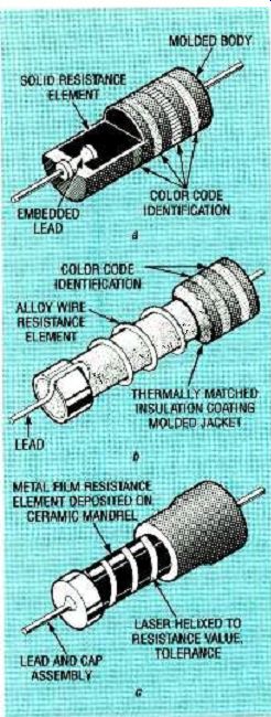
FIG. 3--The CONSTRUCTION OF AXIAL LEADED FIXED RESISTORS is shown for carbon
composition (a), wirewound b), and metal-film (c).
Wirewound resistors
Wirewound resistors are classified as power or precision
components, and both types are made by winding resistance wire on ceramic or epoxy mandrels and terminating each end of the wire with a leaded end cap as shown in Fig. 3-b.
Power wirewound resistors are made by winding a single layer of resistive alloy wire around a ceramic mandrel. The winding is then coated with an insulating material such as vitreous enamel (an inorganic ceramic) or silicone to protect it from moisture and damage while insulating it from contact with surrounding objects. The winding can become hot in normal operation.
Resistance wire is selected for uniform resistance properties, low temperature coefficient, and ability to withstand high temperature. Nickel chromium alloy (nichrome) is commonly used to obtain high resistance values, and copper alloys are used for low resistance values.
Resistance values of commercial power wire-wounds range from less than an ohm to greater than a megohm, and resistive tolerances can be from ±2% to ± 10 %. Power ratings can be as high as 1500 watts and TCR's can be as low as ± 20 ppm/ °C. A power resistor's normal power rating can be doubled by inserting it in an aluminum case with heat-radiating fins, and mounting the case on a heatsink.
Precision wirewound resistors are usually made as multilayer coils wound on epoxy mandrels. Copper-alloy resistance wire is used for low resistance values, and nichrome wire is used for high resistance values. Precision wirewound resistance values range from less than an ohm to 60 megohms, resistive tolerances can be less than 1%, and TCR's can be as low as 0.5 ppm/ °C. Power ratings, less important in their applications, are typically to 2 watts.
Metal-film resistors
Metal-film resistors are made with different resistive elements, and they can be classed as general purpose, precision, and semi-precision. Thin films include nickel-chromium alloy that are less than one-millionth of an inch thick; thick films include cermet and proprietary metal glazes that are more than one-millionth of an inch thick.
Metal-film resistors offer good thermal stability and generally low noise ratings.
Figure 3-c is a cutaway drawing showing the general method for making most metal-film resistors. Thin resistive films are deposited on a long ceramic rod or mandrel in a high-vacuum chamber by vacuum deposition. By contrast, thick films are applied by screening or spraying resistive inks on a similar mandrel before the mandrel is fired.
The mandrels are then cut apart into individual resistor bodies, and leaded end caps are fitted on the ends. 'Dimming to the nominal resistance value is done with a laser in a closed loop circuit under computer control. The resistive film is removed in a spiral pattern whose length sets the desired resistance value. Insulating epoxy jackets are then applied.
Nickel-chromium alloy metal film is suitable for a resistance range of about 1 ohm to 1 megohm with tolerances as low as ±1%. TCR's can range from as low as ± 25 ppm/°C to ± 200 ppm/ °C. Power ratings can be up to 5 watts, and working voltages can exceed 200 volts.
Cermet-film resistor elements are prepared by mixing precious metal with a binder to form an ink and screening it on ceramic mandrels before the mandrels are fired. Cermet resistors have values to 10 megohms, resistive tolerances as low as 1%, TCR's as low as 25 ppm/°C, and power ratings to 3 watts.
Carbon-film resistors
Carbon-film resistors are made in the same general way as cermet metal-film resistors, as shown in Fig. 3-c. These resistors have gained in popularity for general purpose applications because they cost less than carbon composition resistors. Because they are widely used in protected, low voltage transistorized circuits, they do not need to be as rugged.
Carbon-film resistors are available with resistance values from about 1 ohm to 10 megohms with resistive tolerances as low as ± 5% , TCR's under 200 ppm/ °C, and power ratings up to 3 watts. They are less noisy than carbon-composition resistors, and are less likely to be affected by humidity.
Common characteristics
All resistors exhibit some capacitance and inductance. Figure 4 is the equivalent circuit for a resistor operating at a high frequency. An effective inductance is in series with the nominal resistance, and both are shunted by an effective capacitance. Both inductance and capacitance are caused by the composition of the resistive element and its connecting leads.
COMPONENT SERIES RESISTANCE INDUCTANCE
SHUNT CAPACITANCE
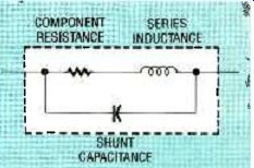
FIG. 4--THE EQUIVALENT CIRCUIT FOR A RESISTOR operating at high frequencies
shows that stray inductance and capacitance, called parasitics, can be present.
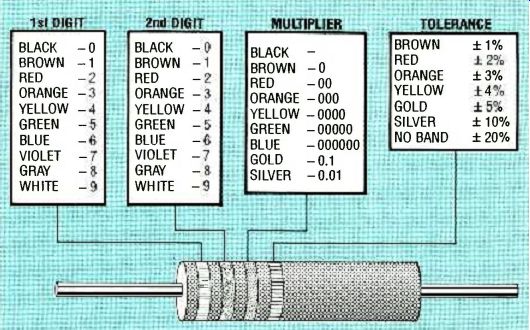
FIG. 5--THE EIA STANDARD COLOR CODE FOR FIXED RESISTORS is based on
colored stripes that are read from left to right to give resistance value
and tolerance.
These undesirable effects, L and C, are called parasitics.
The inductance is negligible in carbon-composition resistors, but somewhat higher in both metal- and carbon-film units. Inductance can, however, be a serious consideration with wirewound resistors operating at high frequency because they are coils. This inductance can be reduced by a winding technique called bifilar winding. A length of resistance wire is folded back on itself before being wound on the mandrel.
This cancels most of the parasitic inductance.
The true value of a resistor also varies with ambient temperature, humidity, age, and applied voltage. The magnitude of these variations depends on resistor composition.
Resistor coding
The values and tolerances of axial-leaded resistors can be read from alphanumeric markings (e.g. 4.7K, 5 %) or by interpreting colored bands on them.
The Electronic Industries Association (EIA) color code, shown in Fig. 5, is now the most widely used code in North America. (It agrees with U.S. military specification MILR-11). Bands of different color designate both resistance value and tolerance. The first two bands denote the first and second digits of the resistance value, and the third band indicates the multiplier--the number of zeros that follow the first two digits. The fourth band gives resistance tolerance.
A resistor with four colored bands can be identified by reading the colors from left to right yellow, violet, orange, silver. These identifies it as a 47,000-ohm resistor with a ± 10 % tolerance.
A fifth band found on MIL R-39008 resistors denotes reliability:
Brown = 1.0 %, Red = 0.1 %, Orange = 0.01% , and Yellow = 0.001%
Wirewound resistors may have a double-width first band.
A final blue band indicates the resistor is recognized by Underwriters Laboratories as failsafe.
Some general-purpose and semi-precision film resistors may have a final white band to indicate that its leads can be soldered. Also, precision film resistors may have three rather than only two significant-figure bands.
As in many other areas of electronics, Government specifications and standards set the acceptance level for resistors. In the U.S., for example, military standards are referenced in most manufacturer's catalogs as a quality benchmark. Among the military specifications referenced are MIL-R-11 (four-band color code identification) and MIL-R-10509 and MIL-R-22684 for metal-film resistors. The procurement of high-reliability, military-qualified resistors is mandatory in many military and aerospace contracts.
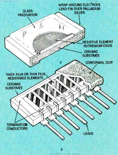
FIG. 7--SPECIAL FIXED RESISTORS include the chip resistor (a), and a single-in-line
package (SIP) network (b).
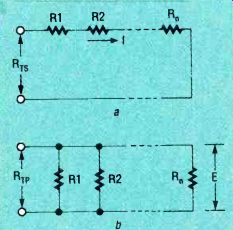
FIG. 6-THE EFFECTIVE VALUES of connected resistors can be calculated by
simple formulas. Resistors connected in series are shown in (a), and those
in parallel are shown in (b).
Resistors in series
Certain formulas apply when resistors are connected in series and parallel in DC and low-frequency AC circuits. Figure 6--a shows n resistors connected in series. In a series circuit, the current I flowing in each resistor is the same. The total equivalent resistance of the series circuit Rtotal is equal to the sum of the individual resistors: Rtotal = R 1 + R2 + R3... Rn If n equal resistors are connected in series, the total equivalent resistance is equal to the product of the value of an individual resistor and n: Rtotal = nR
The maximum voltage Etna, that can be applied across a series of resistors is equal to the sum of the rated continuous working voltage (RCWV) of each resistor: Ems, = (RCWV)1 + RCWV)2... +(RCWV)n Resistors in parallel Figure 6-b shows n resistors connected in parallel. In a parallel circuit, the voltage E across each resistor is the same. The equivalent resistance of two resistors, R1 and R2 in parallel, is equal to their product divided by their sum: R = R1 x R2 /R1 + R2 For n equal resistors in parallel, the equivalent resistance is equal to the value of an individual resistor, R1, divided by n: Rtotal = R1 /n
For n resistors with different values, the equivalent parallel resistance is equal to 1 divided by the sum of the reciprocals of the individual resistor values: Rtotal = 1 /1/R1 + 1/R2 + 1/R3 +....1/R The maximum voltage that can be applied across resistors in parallel is limited by the smallest value of RCWV for a resistor in the circuit.
Special resistors
There are many different kinds of fixed resistors made for special applications. In general, most are manufactured with the same kinds of resistive elements that are used in making conventional fixed resistors.
Therefore, all the technology and formulas previously discussed apply to those products as well. Special resistors include high-voltage resistors, chip resistors, and packaged resistor networks.
High-voltage resistors are resistors that are effective at voltages as high as 40,000 volts.
These can be manufactured as axial-leaded, carbon-film resistors that are hermetically sealed in glass capsules.
Chip resistors are basically thin- or thick-film resistors that have been deposited on a ceramic substrate as shown in Fig. 7-a. Ruthenium-oxide thick-film cermet is widely used as a resistive element in commercial-grade chip resistors for surface mounting. Wraparound electrodes permit solder bonding to the circuit board, and glass passivation protects the resistive element from environmental stresses.
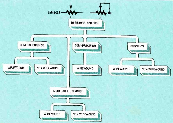
FIG. 8-THIS VARIABLE-RESISTOR FAMILY TREE shows how potentiometers are
classified in industry by resistive element, function and application. Schematic
symbol (a) shows a voltage divider, and symbol (b) shows a rheostat.
The typical power rating for a chip resistor is 1/8 watt or less.
Chip resistors for surface mounting are formed in a 1.6 x 3.2 millimeter (0.125 x 0.063 inch) standard size to permit them to be picked up and placed by automatic machines.
Resistive networks are arrays of thick- or thin-film resistors deposited on a common substrate and packaged for ease of assembly on circuit boards.
They are classed as DIP (dual-inline package) or SIP (single-inline package) networks. A SIP network is shown in Fig. 7-b.
DIP and SIP network conductors are formed as silver-palladium powders in a volatile binder screened on the ceramic substrates and fired. These conductors are brought out to the pins that are brazed to the edges of the substrate. The conductors can also form a variety of interconnection patterns. In standard commercial networks, the resistors have the same value, but networks with different values can be custom ordered.
Resistive networks are used for pull-up and pull-down transitions between logic circuits, as sense amplifier terminations, and for LED display limiting. DIP networks, formed by epoxy molding, are available with 14 or 16 pins. They can be inserted by the same machines that insert DIP-packaged IC's.
SIP networks, by contrast, typically have 6, 8 or 10 pins on one edge for vertical mounting to save PC board space. They are packaged by epoxy molding or conformal coating.
Standard commercial thick film resistive networks have resistor values that range from 10 ohms to 10 megohms with TCR's of ± 2%. Total power dissipation of 1/4-watt is a typical upper limit for the package.
Resistor networks are also available in small-outline IC (SOIC) packages miniature DIP'S with stub leads-as well as open network packages, and hermetic-sealed leadless chip carriers for surface mounting.
Preferred values
By international agreement, general-purpose resistors are manufactured in a limited number of preferred nominal values that are-'related to each other in a logical order. The number of values per decade is related to a distribution of desired resistance tolerance. Thus, if a precision of ± 20% is adequate for some design requirement, the entire spectrum of possible resistance values in the 80-ohm to 800-ohm decade can be adequately spanned with just six preferred resistors with the nominal values and tolerance ranges shown in Table 3.
TABLE 3 COMMON FIXED RESISTOR VALUES AND TOLERANCES
Value, nominal | Range
The values in Table 3 increase logarithmically, in increments of about 50 %. This range of preferred values can be expanded in decade multiples and sub multiples to span all possible resistance values from below 10 ohms to greater than 10 megohms. Resistor manufacturers refer to this set of values as the 20% tolerance series, but in most European countries it is known as the E6 series because it is based on six values per decade.
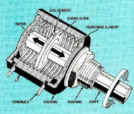
FIG. 9--A CUTAWAY OF A MULTITURN PRECISION POTENTIOMETER shows how the
wiper tracks around the inside of the helical resistance element for high
resolution. 6
Variable resistors
Variable resistors are commonly called potentiometers or pots. These components include a means for changing their nominal resistance values by the manual movement of a contact or wiper over the resistive element. The qualities of variable resistors depend on their resistive elements, the size of those elements, and the configuration or package style of the component.
All potentiometers are the electrical equivalents of three terminal resistors shown schematically at the top of Fig. 8.
Symbol a depicts a voltage divider. However, symbol b depicts a rheostat, organized by connecting the wiper terminal with one other terminal. Thus, the wiper shorts out part of the resistance element so that the value of the resistive element can be changed with each setting.
Figure 8 is a block diagram "tree" showing how potentiometers are classified as general purpose, semi-precision, and adjustable (trimmer). General purpose and semi-precision units are also called volume controls or panel potentiometers.
Resistive elements are classed as wirewound or non-wirewound (e.g. conductive plastic, carbon, and cermet).
Precision potentiometers
A potentiometer with an accuracy of 1% or greater is defined as a precision potentiometer. These variable resistors are generally considered to be instruments rather than electronic components. A close relationship is maintained between the position of the wiper and the potentiometer's resistive (or output) value.
Precision potentiometers were important parts of analog and hybrid computers where accuracy of the output was dependent on the precision of the potentiometer. Precision was determined by such factors as resolution, thermal stability, and repeatability--the ability of the wiper to return to the same point on the resistive element and reproduce the same voltage or current output.
Modern commercial precision
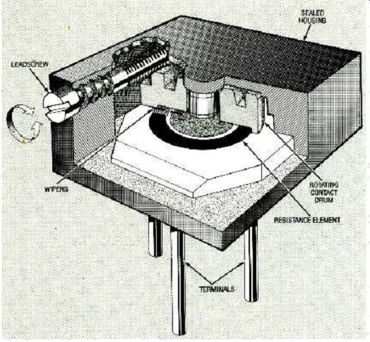
FIG. 11--A CUTAWAY OF A TRIMMER POTENTIOMETER shows the adjustment mechanism.
The three pins permit it to be organized as a voltage divider or rheostat.
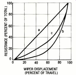
FIG. 10--POTENTIOMETER TAPERS include linear (a), nonlinear logarithmic
(b) and special (c). potentiometers look very much like panel mounted volume
controls. Most are made as applications specific products, but certain commercial
units are available off–the-shelf. The potentiometers can be either single-turn
or multiturn for higher resolution.
Single-turn precision potentiometers have planar (circular) resistive elements, but multi turn precision potentiometers have helical elements. Figure 8 is a cutaway view of a multiturn potentiometer whose wiper rotates and traverses axially down the length of case while tracking the helical resistive element.
Most multiturn potentiometers are actuated with vernier dials to permit repeatability.
Their resistive elements are wirewound or hybrid helixes.
Hybrid elements are wirewound helixes coated with conductive plastic. Up to ten turns may be required for the wiper to track the entire length of the element.
The resistance elements of single-turn precision potentiometers are most likely to be conductive plastic or cermet rather than wirewound today. Conductive plastic elements are made by mixing carbon with a suitable plastic binder to yield a sheet with uniform volumetric resistance. It can be cut or stamped as uniform C-shaped elements or shaped for special functions. This material exhibits good linearity and long rotational life.
Most standard, off-the-shelf precision potentiometers have linear tapers-resistance values that are proportional to wiper movement between the two end terminals as shown in Fig. 10-a.
If the resistance value is not directly proportional to wiper motion, the wiper is said to have a nonlinear resistive element. Tapers are produced by shaping the resistive element. The variation in resistance value (and output) can follow the square law as shown in Fig. 10-b or other mathematical function as shown in Fig. 10-c.
Panel controls
Panel or volume controls are general purpose potentiometers whose setting is determined subjectively. These controls set audio volume in radios and TV's, and brightness on TV and computer CRT's. A precise relationship between wiper setting and resistance value is not required.
Panel potentiometers have wirewound or non-wirewound (e.g. carbon, conductive plastic or cermet) resistance elements.
The performance of these components is related to their resistive elements (e.g. range of values, tolerance, TCR, and power handling ability.) Carbon elements wear with repeated wiper rotation, and cermet elements tend to abrade the wiper.
The elements of panel potentiometers can also be tapered as shown in Fig. 10.
Some panel potentiometers are assembled from modules and have a common shaft. This permits them to be ganged so that one axial shaft motion changes two or more resistive elements all at the same time.
Panel potentiometers are also made for PC board and surface mounting.
Trimmer potentiometers are called "set and forget" components because they are usually set only during final test and checkout of a product. Figure 11 shows a cutaway view of a trimmer. However, trimmers are also reset after circuit repairs, or during instrument recalibration to overcome the effects of component aging. Trimmers are usually inaccessible to the end user.
Made as printed circuit board or surface-mount components, trimmers can have wirewound resistive elements or those made of carbon or cermet. As in panel potentiometers, performance and cost relate to the resistive element selected. Some trimmers can be set directly with a screwdriver, and others are set indirectly with precision multiturn lead-screw wiping mechanisms as shown in Fig. 11. Trimmers with linear resistive elements are set by manually sliding the wiper along the element.
Trimmer case sizes have been standardized. Some trimmers have open cases with their resistive elements exposed, and others are sealed to prevent the intrusion of solder flux and circuit-board flux cleaning solutions.
------------------
Also see: DRAWING BOARD (PLL)