by RAY MARSTON
Learn more about capacitors-how they are made, and how you can apply them more cost-effectively in your circuits.
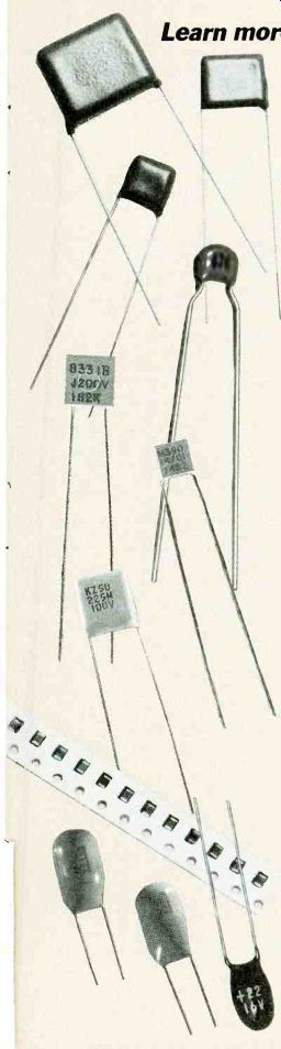
CAPACITORS RANK NEXT TO Resistors as the most widely purchased electronic components. Fixed and variable capacitors for electronics available from commercial sources have capacitance values from a few picofarads (pF) to farads (F). And these components are made from an amazingly wide variety of materials.
The outstanding trend in capacitor design and manufacture over the past 85 years--particularly since the arrival of the integrated circuit-has been miniaturization. The objective of all efforts has been to cram as much capacitance as possible into ever smaller packages, while at the same time increasing their reliability.
To gain a better understanding of this trend, and to appreciate what has been accomplished, it is worth reviewing the fundamental capacitor formulas. The ability of a capacitor to store electric energy is a function of its geometry and the physical characteristics of its dielectric.
The amount of energy that a capacitor can store is given by the equation: Q = CE
... where...
Q = the magnitude of the stored charge in coulombs
C = capacitance in farads
V = applied voltage in volts
Figure 1-a shows the simplest capacitor and identifies its principal parts and physical variables; Fig. 1-b is the accepted schematic symbol in North America for a fixed capacitor, and Fig. 1-c is the accepted symbol for a variable capacitor.
Capacitance in farads is determined by:
C = kA/d
...where k is the dielectric constant (permitivity), the ratio of the ability of a dielectric material to store electrostatic energy to that stored by a vacuum between the same electrodes (see Table 1).
A = directly opposing plate area
d = distance between the plates
Different multiplying factors can be applied to this equation so that the value for C is in microfarads or picofarads when A and d are measured either in inches or millimeters. Nevertheless, important engineering tradeoffs can be seen from both of these equations: To store a given charge, more voltage is needed for a small capacitor than a large one.
If the opposing plate area, A, is held constant, the value of capacitance can be increased by:
a. Decreasing the thickness of the dielectric, h.
b. Using a dielectric with a higher constant, k.
c. Doing both (a) and (b) simultaneously.
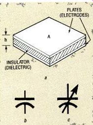
FIG. 1--A BASIC PARALLEL-PLATE capacitor has parallel metal plates or electrodes
separated by a dielectric that can be air or a solid insulator.
While not apparent from the formulas, other facts about capacitors to be considered are: The maximum voltage that can be impressed across a capacitor, without destroying it, depends on the dielectric and the separation of the plates.
For a given dielectric, the allowable maximum voltage can be increased as the distance between the plates is increased.
The volumetric efficiency of capacitors has been improved within the constraints mentioned. How this has been done will be explained in the discussion of each of the. most common capacitor manufacturing technologies.
Advanced circuit manufacturing methods have increased demand for miniature chip capacitors for hybrid circuits and surface mounting. New plastic film and ceramic dielectrics now offer a wider range of operating characteristics than was available ten years ago; metalizing has reduced capacitor weight and size by eliminating metal foil from many film capacitors now being produced.
The quality and reliability of electrolytic capacitors has been improved with more effective methods for etching foils, the introduction of better electrolytes, and improved sealing.
Solid electrolyte tantalum capacitors made as dipped radial or chip units are becoming more popular. Capacitors made from mica and glass have faded away to become specialty items, with their former functions largely performed by multilayer ceramic capacitors. Moreover, ceramic disk caps are rarely specified in new designs; they have been replaced by smaller, easier-to-place ceramic tubular capacitors.
The fabrication of increasing numbers of capacitors within very large scale integrated circuits such as microprocessors and digital signal processors has not reduced sales of discrete capacitors; in fact, the sales of certain kinds of capacitors have increased because of the proliferation of IC's. Moreover, capacitors are necessary in the external circuitry for the dedication of such multifunction linear IC's as compandor and modulation chips. Thin- and thick-film capacitors are being formed on ceramic substrates for networks and hybrid circuits that operate well into the microwave band.
Variable capacitors, still used primarily in radio-frequency circuits, are also being made from improved plastics and ceramics, a departure from their traditional dielectrics of air, glass, and ceramic, to reduce their size, extend their capacitance range, and cut cost.
Capacitor terms
Capacitors are widely specified with a glossary of widely accepted technical terms. A knowledge of these terms will be helpful to anyone who specifies or uses capacitors.
Capacitance. The basic unit for capacitance is the farad, but most capacitors for electronics applications need capacitance values that are only small fractions of a farad: microfarad (pF one-millionth of a farad) and picofarad (pF one-millionth of one-millionth of a farad). Ambient temperature. The actual value of a capacitor depends on the temperature of its environment, known as ambient temperature. Percent capacitance change, a function of temperature. is referred to room temperature, 25 °C. Capacitive tolerance is the variation in capacitance value of the capacitor expressed as a percentage of its value at room temperature, 25 °C, which is referred to as the nominal value.
Temperature coefficient (TC) is the change in a capacitor's capacitance per degree change in temperature, expressed in parts per million per degree Celsius (ppm/°C). The coefficient can be positive, negative, or zero. The letter P indicates that the coefficient is positive: N if negative.
The designation NPO identifies a zero-temperature coefficient.
Rated working voltage is the maximum permissible operating voltage at which a capacitor can be continuously operated at maximum rated voltage (without derating). This rating must be specified as AC or DC because they are not usually equal.
-------------
TABLE 1
DIELECTRIC CONSTANTS | COMMON CAPACITOR MATERIALS
Dielectric k
Vacuum 1
Air 1.0006
Polystyrene 2.5
Polyester 3
Mica 5
Aluminum oxide 7
Tantalum oxide 25
Ceramic (low k) 10
Ceramic (high k) 10010,000
--------------
Surge voltage is the maximum instantaneous voltage to which the capacitor should be subjected; exceeding that voltage will cause the capacitor's breakdown. Surge voltage is higher than working voltage.
DC leakage is the small amount of direct current that flows in a capacitor at a specified voltage. Caused by the presence of free charge carriers within the dielectric, it is the reason why a charge cannot be stored indefinitely in a capacitor; eventually it leaks off.
Insulation resistance.(IR) is the resistance of the dielectric.
High resistance results in low leakage current. This variable is inversely related to ambient temperature.
Capacitive reactance (Xc) of a capacitor is inversely related to the product of capacitance and frequency in accordance with:
Xc = 0.159/fxC ... where 0.159 is a conversion constant
Xc = capacitive reactance (ohms)
f = frequency (hertz)
C = capacitance (farads)
Power-factor (PF) expresses the ratio of energy dissipated to the energy stored in a capacitor, as a percent. It typically exhibits a negative slope below room temperature and positive slope above it.
Equivalent series resistance (ESR), expressed in ohms, is the sum of all internal resistance values of a capacitor.
These include lead resistance, terminal losses, and dissipation in the dielectric. ESR increases with frequency.
Impedance (Z) of a capacitor is the total opposition it offers to the flow of alternating current at a given frequency: Z = Xc2 + (ESR)2
where Z = impedance (ohms)
Xc2 = capacitive reactance (ohms)
ESR = equivalent series resistance (ohms)
Capacitive impedance is inversely proportional to frequency and temperature; ideally, it equals capacitive reactance.
Dissipation factor (DF) of a capacitor is the ratio of energy dissipated to energy stored in the dielectric. DF is a figure of merit for the quality of a capacitor.
DF = ESR/Xc X 100%
Ideally capacitors have low values of DF over wide temperature ranges.
Q or Quality factor is the ratio of energy dissipated to energy stored, so it is the reciprocal of dissipation factor at low frequencies.
Q` = 1 /DF = Xc/ESR
The highest quality capacitors have high Q's.
Ripple current is the result of a periodic AC voltage wave superimposed on the DC voltage applied to the capacitor. Ripple current flowing through the ESR of a capacitor can generate heat, raising the temperature of the capacitor.
Volumetric efficiency is a measure of relative capacitance per unit volume. One capacitor has a higher volumetric efficiency than another capacitor of the same size (volumetric dimensions) if it is able to store more charge, or has a higher capacitance rating.
Capacitor applications
Capacitors have many different applications in electronic circuits: Blocking-limiting the flow of direct current or low frequency alternating current without significantly affecting the flow of high-frequency AC. Bypassing-providing a low-impedance path around a circuit component to permit the flow of alternating current Coupling /decoupling-coupling or decoupling alternating signals between circuits and systems.
Energy storage--storing electric energy for later release to power a device or circuit.
Filtering--removing the DC component from a signal.
Smoothing--reducing the ripple on an input signal
Timing-providing capacitance value in timing circuits.
Tuning--providing capacitance value for tuning in a tank circuit.
Fixed capacitors
Figure 2 is a diagram showing how fixed capacitors are classified as electrostatic and electrolytic. Electrostatic capacitors are so named because an electrostatic charge is stored between opposing plates. They are named for the dielectrics between their plates. This can be air or a vacuum or such solid materials as plastic film, ceramic, mica, and glass.
Electrostatic capacitors are further classified by packaging method: leaded or non-leaded (chip); radial or axial leaded; molded, conformal coated, or dipped in an encapsulant, typically epoxy. A film capacitor can be further classified by the specification of its plastic film such as polyester or polycarbonate.
Electrolytic capacitors are made of metals, normally either aluminum or tantalum, that form extremely thin anodic oxide layers of high-dielectric constant and good electrical characteristics during electrolytic processing. These capacitors are classified by the metal from which their anodes are made-aluminum or tantalum-and capacitor configuration: wet foil, wet slug, or dry slug (solid electrolyte).
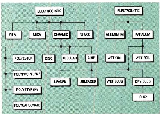
FIG. 2--POPULAR FIXED CAPACITORS are organized as electrostatic and electrolytic,
and identified by their dielectric and package style.
Film capacitors
Film capacitors are made with thin dielectric plastic films such as polyester (Mylar), poly-carbonate, polystyrene and polypropylene that is 0.06 mil (1.5 micrometers) to over 0.8 mil (20 micrometers) thick. The electrodes of film capacitors can be metal foil (film/foil) or metal directly deposited on the film (metalized). Film/foil capacitors are made of dielectric film sandwiched between tin or aluminum foil plates (about 0.25-mil thick). They are most widely specified for energy storage, pulse discharge, and arc suppression applications.
The plates of metalized capacitors are very thin vacuum-deposited layers of aluminum or zinc, which permits these capacitors to be smaller and lighter than film/foil capacitors with the same capacitance ratings.
These capacitors can be made as shown in Fig. 3, or the metalized film can be cut into rectangles and stacked. The stacks are then leaded and molded in a protective encapsulant package.
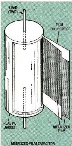
FIG. 3--VIEW OF PLASTIC-FILM capacitor shows how metalized: film dielectric
(with leads connected) is rolled into a cylinder and jacketed with molded
or conformally coated plastic.
Self-healing is a very important feature of metalized-film capacitors. A localized dielectric breakdown caused by a transient overvoltage will not necessarily cause capacitor failure because the metalized film around the fault evaporates without shorting the adjacent metalized plates. This response isolates the fault and effectively restores the electrical properties of the capacitor.
Both film/foil and metalized film capacitors are made with axial or radial leads in a variety of case sizes. They can be hermetically sealed in tubular or rectangular metal cases, or encapsulated by molding or con-formally coating with epoxy.
Film capacitors are most widely specified for capacitance values from 500 picofarads to 10 microfarads. (Refer to Table 2.) Their working voltages typically range from 50 volts DC to 630 volts DC although they can have higher ratings. Capacitance tolerance is typically from ± 1% to ± 10% Film dielectrics The four most widely used film dielectrics are: Polyester (trade named Mylar) capacitors are the most popular general-purpose film capacitors. This film permits high volumetric efficiency, low leakage, and a moderate temperature coefficient. Some film /foil and metalized units can operate to 125 °C at 50% of rated voltage.
Metalized polyester units can perform blocking, coupling, decoupling, bypass, and filtering.
Polycarbonate capacitors have operating temperatures from-55 °C to as high as +125°C with proper voltage derating.
Capacitive tolerances can be as low as ±5 %. This dielectric film offers high insulation resistance and stability.
Polystyrene capacitors have characteristics that are similar to those of polypropylene, but they have lower volumetric efficiency. They have capacitive tolerances as low as 1 %. Film/foil units are widely used in inductive capacitive filters.
Polypropylene capacitors have higher volumetric efficiency than polyester capacitors.
Except for AC rating, their characteristics are similar to those made from polystyrene.
They have tolerances as low as ±2 %. These capacitors are specified where precision, reliability, and low losses are important: e.g. tuning, filtering, and timing.
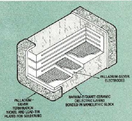
FIG. 4--CUTAWAY VIEW OF A CERAMIC MULTILAYER CHIP capacitor shows noble-metal
electrodes deposited on thin layers of ceramic dielectric which are then
pressed and fired to form a monolithic unit.
Ceramic capacitors
There are three ceramic capacitor styles: single-layer disc, single-layer tubular, and monolithic multilayer. There are three principal classes of ceramic dielectric based on their k rating: Class I, II, and III. Low-k materials have linear characteristics, and their properties are independent of frequency over their normal range. They are suitable for resonant-circuit or filter characteristics. High-K ceramics have very high effective dielectric constants. They are suitable for coupling and decoupling applications.
Disc ceramic capacitors are made by metalizing both surfaces of a thin low-k (Class III) ceramic disc with silver-based ink to form the electrodes, firing the disk, and soldering on radial leads. They are jacketed by dipping in phenolic resin or epoxy. These capacitors are being replaced by tubular ceramic units made of the same materials that save circuit board space and permit automatic parts placement.
Tubular ceramic capacitors are made by coating the inner and outer surfaces of Class III ceramic tubes with silver-based thin-film ink, firing, and attaching leads to the tube before jacketing it by epoxy dipping.
Monolithic multilayer ceramic (MLC) capacitors are made by screening thin-film, precious metal-based conductive ink on thin layers of "green" or unfired layers of higher k (Class II and III) ceramics. The screened layers are then stacked (up to 40 layers), compressed, and fired to form monolithic capacitors, as shown in Fig. 4.
If the MLC capacitor is to be a chip capacitor for a hybrid circuit or surface-mounting, conductive-metal terminations are plated on its ends, as shown in Fig. 4. The terminals of surface-mount chips are further plated with lead-tin alloy to improve the terminal-to-pad solder joints.
Demand for MLC chips has risen with the worldwide growth of surface mounting.
Chip MLC's will withstand the molten-solder temperatures encountered in reflow and wave soldering. They are available in standard sizes to fit the grasping tools in automated pick and place machines. The most common sizes are 0.08 x 0.05 inch (0805), 0.125 x 0.063 inch (1206), and 0.05 x 0.225 inch (2225).
----------------
TABLE 2
CHARACTERISTICS OF POPULAR FIXED CAPACITORS
----------------
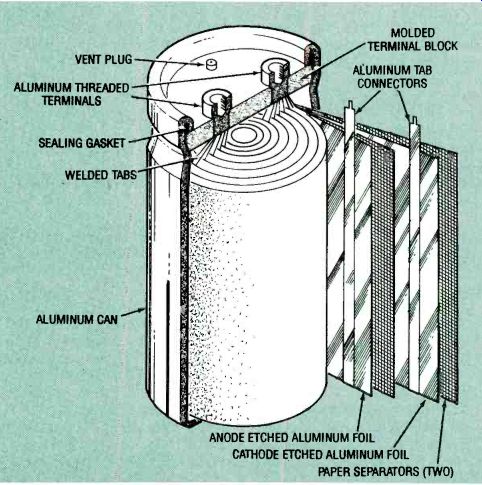
FIG. 5-VIEW OF AN ALUMINUM ELECTROLYTIC CAPACITOR shows how the cathode
(porous paper spacer filled with liquid electrolyte) is sandwiched between
the oxidized aluminum anode foil and cathode connection foil, rolled into
cylinder, and then sealed in an aluminum can.
Cylindrical leadless capacitors are also made for surface mounting. These capacitors have metalized-band contacts on the ends of their epoxy-coated bodies for soldering to lands of surface-mount circuit boards.
For conventional through-hole mounting, axial or radial leads are attached, and the chip is jacketed by dipping or molding in epoxy. MLC capacitors are specified for bypassing noise to ground, timing, and frequency selection.
Ceramic dielectrics
Ceramic dielectric materials are classified by dielectric constant k as Class I, Class II and Class III: Class I dielectrics are made by mixing magnesium titanate (for a positive temperature coefficient) with calcium titanate (for a negative coefficient) to form a dielectric material with low k values, and properties essentially independent of frequency. They exhibit ultra-stable temperature coefficients of ± 30 ppm/°C over the temperature range of-55° to + 125 °C. Class I includes NPO (negative, positive, zero), also known as COG and BY. Class II dielectrics are high-k materials (called ferroelectrics) based on barium titanate. With the addition of barium stanate, barium zirconate, or magnesium titanate, their dielectric constants can be lowered from values as high as 8000 for increased temperature stability.
These dielectrics include general purpose X7R (BX) and Z5U (BZ). Class III dielectrics were developed primarily for ceramic disc capacitors because they permit high volumetric efficiency. But this introduces a tradeoff between high leakage resistance and low dissipation factor. Class III capacitors have low working voltages.
Other electrostatic capacitors
The dielectric in a mica capacitor is mica, a natural mineral that is chemically inert and very stable. The capacitor is generally made as a "sandwich" of alternating layers of tin-lead foil plates and mica. These capacitors can operate at temperature up to + 150 °C. Silvered mica capacitors offer greater mechanical stability and more uniform characteristics. They are made by screening and firing a thin layer of silver on the surface of the mica to form the plates.
Glass capacitors are made by stacking alternate layers of thin glass dielectric in a sandwich structure similar to that of the mica capacitor. They are specified where temperature stability is a requirement.
Electrolytic capacitors
The dielectrics of aluminum and tantalum electrolytic capacitors are oxides formed by electrochemical reaction with those metals. There are three styles of electrolytic capacitor: wet foil, wet slug, and dry or solid slug.
Aluminum electrolytic capacitors are wet foil units, but tantalum capacitors are also available as wet-slug and solid slug units. They can be polarized or non-polarized.
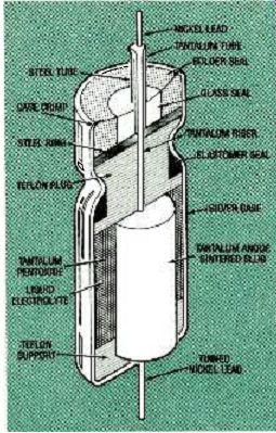
FIG. 6--CUTAWAY VIEW OF WET-SLUG tantalum capacitor shows tantalum slug
filled with wet-electrolyte sealed in a silver case.
All electrolytic capacitors exhibit high capacitance per unit volume (high volumetric efficiency). An aluminum electrolytic capacitor can store four, five or more times the charge of an equivalent-size film capacitor, and a tantalum capacitor can store three times as much charge as an equivalent aluminum capacitor.
However, aluminum electrolytic capacitors have higher DC leakage and lower insulation resistance than electrostatic capacitors. Moreover, they have higher power losses because of their higher equivalent series resistance (ESR). The anodes of aluminum electrolytic capacitors are made from high-purity aluminum foil that has been electrochemically etched to increase its effective surface area. A thin aluminum-oxide-dielectric layer, about 0.01 micron, is then grown on the etched foil in another electrochemical process. The enlarged surface area of the etched foil provides a far larger dielectric surface than would be possible with unetched foil.
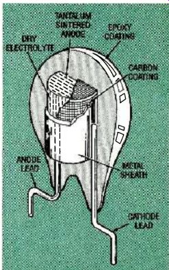
FIG. 7--CUTAWAY VIEW OF A SOLID tantalum capacitor jacketed by dipping
in epoxy.
A porous paper spacer filled with a liquid electrolyte is sandwiched between the etched and oxidized anode foil and another aluminum cathode foil. The liquid electrolyte is the actual cathode, but the cathode foil is in contact with the liquid electrolyte and is needed to complete the electrical circuit.
After attaching a series of connecting tabs to the foils, the "sandwich" is rolled, as shown in Fig. 5, and inserted in an aluminum can, which is then sealed. However, the sealed can has an overpressure vent.
Direct current must flow in only one direction in a polarized electrolytic capacitor. Even short-term current reversal could destroy the oxide dielectric and short-circuit the capacitor. A " + " mark on the case identifies its positive terminal.
Aluminum electrolytic capacitors are made with radial or axial leads, and some styles for switchmode power supplies have spring-metal terminals that snap into circuit board holes. An external plastic sleeve permits off-ground applications for the capacitor.
Nonpolarized aluminum electrolytic caps are essentially two polarized capacitors back-to-back with their cathode terminals connected. The anode terminals make the external circuit connection, while the cathode terminals are isolated by an insulator. Both foils are anodized to form oxide barriers, and they share a common electrolyte-filled porous spacer.
A nonpolarized capacitor has half the capacitance of a comparably sized polarized capacitor with the same voltage rating. Although not as efficient as polarized capacitors, the nonpolarized units are used for AC motor starting and other AC control applications.
Tantalum capacitors
Tantalum electrolytic capacitors are available in three forms: wet-foil, wet slug, and dry slug.
Wet-foil tantalum capacitors are made in about the same way as aluminum electrolytics. As a group, tantalum capacitors exhibit higher volumetric efficiency, more stable characteristics, higher operating temperature ranges, and longer shelf lives than aluminum capacitors. However, they cost more and have lower voltage ratings.
Both wet and dry slug tantalums are made from porous pellets of tantalum. The anode slug is formed by pressing tantalum powder and a binder in a mold, and firing it in a vacuum furnace (sintering) to bond the powder and drive off the binder.
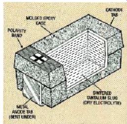
FIG. 8--CUTAWAY VIEW OF A SOLID tantalum capacitor chip for surface mounting
applications.
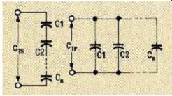
FIG. 9--CONNECTING CAPACITORS in series yields a total capacitance that
is less than that of the lowest-value unit a), but connecting them in parallel
yields a total capacitance equal to the sum of all unit values.
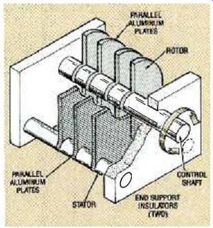
FIG.10--SIMPLIFIED DRAWING of a tuning capacitor shows a concept that is
used in many variable capacitors.
The tantalum oxide dielectric is electrochemically formed in the porous pellet.
Figure 6 is a cutaway view of a wet-slug tantalum capacitor with an acid electrolyte. Its volumetric efficiency about three times that of a comparably sized foil unit. Moreover, wet-foil tantalums are the most reliable of all capacitors.
The high cost of wet-foil and wet-slug tantalums makes them too expensive for most consumer and industrial applications. However, those high-reliability capacitors are widely specified for military electronics and avionics. Military specifications MIL-C-3965 and MIL-C-39006 govern the procurement of military-style wet-foil and solid-slug units.
The solid-anode or dry-slug unit, shown in Fig. 7, is the most popular and economical tantalum capacitor. It has a thin film of manganese dioxide chemically deposited on its tantalum dioxide dielectric to act as a second electrode. Solid-slug capacitors can be sealed in metal cases, or protected by dipping in epoxy as shown in Fig. 7. The solid-slug units have the longest life and lowest leakage of any tantalum caps. Chip capacitors for surface mounting, as shown in Fig. 8, are made by the same process.
Capacitor identification.
Today the capacitor's nominal value (and sometimes its tolerance) are printed on its body where space permits. Values such as 47 and 68 are typically in microfarads, while values such as 120 or 4700 are usually in picofarads. A capacitor might also be marked with its working voltage: for example, 63V or 100V.
Some capacitors are still marked with colored bands based on the EIA system used for identifying resistors. The colors of the bands are read from left to right. A black band represents zero, brown represents one, and red, orange, yellow, green, blue, and violet represent the digits two to seven, in that order. Grey represents eight, and white represents nine. As in resistor coding, a gold band denotes a capacitive tolerance of 5%, while a silver band denotes 10% You might encounter capacitors with obsolete coding schemes in old radios or TV's or at surplus sales. Some of those codes are based on colored dots, spots or "hash marks." It is wise to consult a radio engineering handbook or data reference book published before 1970 if you want to find out how to interpret those codes if you plan to use them in your circuits and are in doubt about their ratings.
Connecting capacitors
Figure 9 illustrates capacitors connected in series and parallel.
The formula for calculating the effective value of two capacitors in series is:
CTS = C1 XC2 /C1 +C2
For two or more capacitors in series it is:
CTS = + 1 /C2 + 1 /C3 + 1/ Cn
For capacitors in parallel the formula is:
XTp= C1 +C2 +C3 +Cn
Variable capacitors
For many years the most prominent variable capacitors were those used to tune radio receivers, transmitters, and oscillators. However, in the latest transistorized equipment they have been largely superseded by varactors or voltage variable capacitors. These are silicon or gallium arsenide PN junction diodes that make use of the variation of junction capacitance with reverse bias. Nevertheless, the design concept embodied in the tuning capacitor lives on in a wide range of miniature, PC board mounted variable capacitors for many different tuning applications.
Figure 10 is a simplified sketch of an air-dielectric tuning capacitor. Its capacitance value can be changed by rotating its control shaft so that the movable set of metal plates (rotor) meshes in different positions with respect to the fixed set (stator). Its capacitance value is greatest when the rotor is fully meshed with the stator.
The rotor plates of tuning capacitors can be shaped so that, with shaft rotation, capacitance variation is linear or nonlinear.
For example, it might follow a nonlinear logarithmic or square law function. Two or more tuning capacitors can be ganged together so that they vary in unison, simultaneously tuning separate circuits to different frequencies.
Trimmer capacitors are "set and forget" variable capacitors made for infrequent adjustment. Many different types are available for commercial and industrial applications. Vane types are miniaturized versions of the tuning capacitor shown in Fig. 10, except that layers of solid dielectric, typically plastic, are inserted between the rotor and stator plates.
Vane-type trimmers with body diameters of less than a half inch are made for PC-board mounting. They have plastic cases and dielectrics of polypropylene, polyethylene, poly-carbonate, or PTFE films. These trimmers are made for screwdriver and/or key adjustment.
There are also simpler trimmer capacitors that permit more limited capacitance variation for high-frequency tuning applications.
------------------
Also see: Link | --Link | --FORCE-SENSING RESISTORS