Give your PC the ranging ability of RADAR with this month's addition to last month's Experimenter project.
By RONALD M. JACKSON
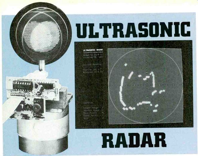
IT'S DIFFICULT TO IMPRESS PEOPLE with a home computer. Even if the computer has a 486 processor running faster than blazes, from the outside it just looks like a tan box. There's not much you can bring up on the screen that will impress them either--they've seen it all before on TV. However, this month's project puts a live-action radar-like display in high-resolution color graphics on your home computer screen-and it's guaranteed to impress. People will be amazed as a blip moves about on the computer's "radar" display, following their movements about the room.
The system works as follows: An ultrasonic rangefinder measures the distances to surrounding objects. (Note that because ultrasonic energy rather than radio frequency is used, this project is more like sonar than radar.) A stepper motor rotates the transducer, giving full 360° coverage. The ultrasonic rangefinder and stepper motor are controlled and interfaced to your home computer by the Experimenter interface presented last month.
The software, written in Microsoft's Quick BASIC for PC-compatible computers, is available on the Electronics Now BBS (516-293-2283), or on disk from the source mentioned in the Parts List. A Macintosh version is also available.
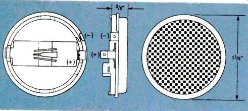
FIG. 1--THE ULTRASONIC TRANSDUCER acts as both a transmitter and receiver.
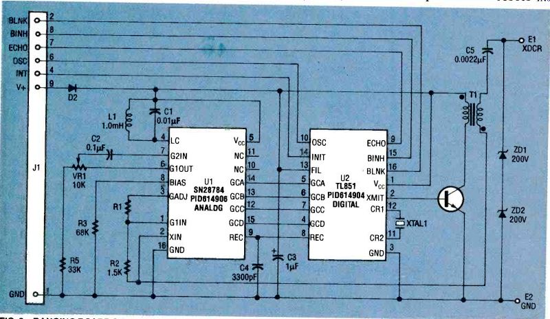
FIG. 2--RANGING BOARD SCHEMATIC. The ranging board provides the high
voltages required to run the transducer, sensitive amplifiers
for echo detection, and control logic.
The rangefinder
Our project uses the same ultrasonic transducer that is used in Polaroid cameras. Note that we will not be building the transducer unit because it is not available as a kit-only as a preassembled surplus unit from the source mentioned in the Parts List. An ultrasonic rangefinder emits a brief pulse of high-frequency sound. Any object hit by the sound produces an echo. The distance to the object is determined by measuring the time delay between the transmission of the original pulse and the return of the echo, which is displayed.
The Polaroid rangefinder is made up of two parts: a transducer and a ranging board. The transducer, shown in Fig. 1, acts as both a speaker and a microphone. It emits the ultrasonic pulse and "listens" for the echo. The ranging board (Fig. 2) provides the high voltages required to run the transducer, sensitive amplifiers for echo detection, and control logic. The only adjustment on the ranging board, VR1, changes the sensitivity of the echo detector. The transducer is mounted on top of the output shaft of a stepper motor, which gives the transducer a 360° field of view. The ranging board mounts beside the stepper motor. Figure 3 shows the entire radar assembly.
The Experimenter controls the ranging board, measures the round-trip time of the pulses. controls the stepper motor, and communicates with your computer. Figure 4 shows the connections between the transducer, ranging board, and the Experimenter. The ranging board uses a nine-conductor flexible cable. The connector for this cable can be installed in the X1 connector mounting area on the Experimenter. The cable has a black stripe on it to indicate pin 1.
The ranging board's power requirements are normally under 100 milliamps, but peak at about 2 amps during the transmit period. Power passes through the GND (pin 1) and V+ (pin 9) signals on the flex cable to connector J1. Due to the inductance of the cable, the ranging board might experience a supply voltage drop of about 4 volts (on a 5-volt supply!) during the transmit period. That can cause the ranging board to malfunction.
To prevent that, install a capacitor of 3000' or greater on the ranging board at J1 between V+ and ground. To ensure that the circuitry on the Experimenter is not affected by the sudden power demand, add a 3001,..F capacitor on the Experimenter end of the cable. It can be added in the wiring grid area adjacent to X1.
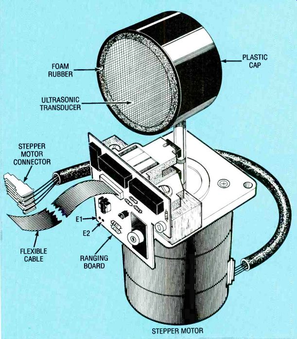
FIG. 3--THE TRANSDUCER IS MOUNTED to the stepper-motor output shaft.
The ranging board is also mounted to the stepper motor.
Figure 5 shows a timing diagram of the ranging-board signals. When the Experimenter sets INIT high, the ranging board sends sixteen high-voltage drive pulses to the transducer. It takes about 360 microseconds to transmit the pulses. The Experimenter waits one millisecond to allow time for pulse transmission and for the transducer to settle down. Then the Experimenter sets BINH high to start the driver "listening" for an echo. If an echo is detected, the ranging board sets ECHO high. The Experimenter ensures the time from BINH going high to ECHO going high. Then the Experimenter resets INIT and BINH low. If no echo is detected in about a half second, the Experimenter cancels the measurement.
The measured time is sent to the computer, which then calculates the distance based on the speed of sound. (The speed of sound in air is about 1100 feet per second, but it varies with temperature, humidity, and barometric pressure.) You can measure the speed of sound for your existing local weather conditions with the program DISTANCE.BAS, which is contained in the self-un-archiving ZIP file on the Electronic Now BBS (516-293-2283) called EXPER1.EXE. Since the Experimenter measures time with 10 microsecond resolution, this program can calculate distances to within about a hundredth of an inch!
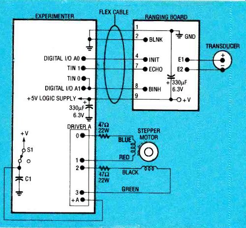
FIG. 4--THE CONNECTIONS between the transducer, ranging board, stepper
motor, and the Experimenter. Capacitors must be added across the power
supply on both the Experimenter and ranging boards. The power to driver
A can be wired to the power switch S1 (as shown), or connected to an
external power supply or battery. The choice of power source will depend
on your selection of stepper motor, and the way the Experimenter is
powered.
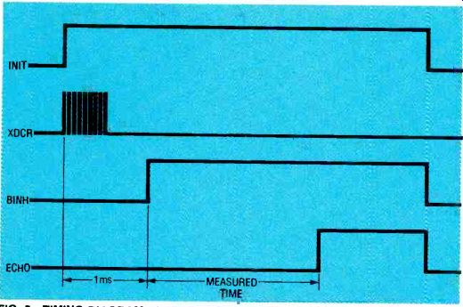
FIG. 5--TIMING DIAGRAM of the ranging-board signals for this project.
The Experimenter sets INIT high, then the ranging board sends
pulses to the transducer. The Experimenter waits for the pulse transmission
and for the transducer to settle down.
Then the Experimenter sets BINH high to start the driver listening for an echo. If an echo is detected, the ranging board sets ECHO high. The Experimenter measures the time from BINH going high to ECHO going high.
The stepper motor
The project uses a stepper motor that rotates the ultrasonic transducer so it scans around the room. A stepper motor differs from an ordinary DC motor that has two wires connected to brushes inside the motor. As the armature rotates, the brushes connect successive commutator bars to windings to provide torque. The motor speed depends on how heavily it is loaded and how much voltage is supplied.
By contrast, a stepper motor has separate wires to each winding. Energizing a winding causes the armature to rotate slightly, typically a few degrees.
By sequentially energizing the coils, the motor can be made to rotate through 360°. By controlling exactly when each winding is energized, the motor can be made to turn through a specified angle at a precisely controlled speed.
A stepper motor is used in this project because it gives precise control of motor-shaft location. If an ordinary DC motor were used, we couldn't control the shaft position and wouldn't be able to take the distance readings at evenly spaced positions. By controlling the number of steps and step rate, the stepper motor will turn the exact angle required between each pulse transmission.
Thanks to the Experimenter's built-in stepper-motor control, the sequencing of the stepper-motor's coils is handled automatically. Your computer tells the Experimenter how many steps it wants the motor to take between readings, and the Experimenter handles all of the timing and sequencing required to step it there.
There are many types of stepper motors available. Low-cost, light-duty stepper motors have either two coils, three coils, two coils with center taps, or four separate coils (see Fig. 6). The Experimenter can drive any of those stepper motors, with drive voltages from 4.5 to 36 volts and currents up to 1 amp.
The numbers given in Fig. 6 show which driver output to connect to each wire of the stepper motor. If you don't have a data sheet for your stepper motor you will have to figure out the coil configuration with an ohmmeter.
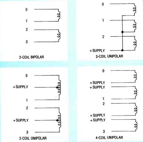
FIG. 6--COMMON STEPPER MOTORS have either two coils, three coils,
two coils with center taps, or four separate coils. The Experimenter
can drive all these stepper motors.
TABLE 1-- STEPPER MOTOR DRIVE TYPES
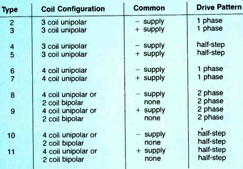
The Experimenter must be "told" the coil configuration of the stepper motor so that it can provide the proper sequencing of outputs. Table 1 shows the available drives for the four stepper-motor coil configurations. Some configurations can be successfully driven with several different kinds of drives.
In choosing between different drives, you must make tradeoffs between the motor's power consumption, torque, and resolution. For example, a unipolar stepper motor with its common leads connected to the + supply can be driven in modes 7, 9, or 11. Mode 7 (one-phase drive) minimizes power consumption, because only one coil is active at any time, although this reduces torque. Mode 9 (two-phase drive) runs two coils simultaneously, providing maximum torque, although the power consumption is doubled.
Mode 11 (half-step drive) alternates between driving two coils and one coil, doubling the number of steps per revolution.
Stepper motors are usually labeled with the step angle (or steps per revolution), maximum coil voltage, and coil resistance (or maximum current). If you use a stepper motor with coil voltages of twelve volts or less, you can run both the stepper motor and the Experimenter from the same power supply.
Some stepper motors draw more current than a small power supply can provide, so a rechargeable battery pack is usually the most economical power alternative.
Let's look at one example of a suitable stepper motor. The motor has four wires terminated in a connector: blue, red, black, and green, in that order.
An ohmmeter shows that the coils are arranged in a two-coil bipolar configuration: blue paired with red and black paired with green. The label says that it's a 1.8° per step motor. That corresponds to 200 steps per revolution in the two-phase drive mode (type 8), or 400 steps per revolution in the half-step drive mode (type 10). The maximum DC voltage listed on the motor is 4.25 volts, with a current of 1.7 amps: it is a heavy-duty ball-bearing motor. We don't need the torque that this motor can produce at its full power rating for this project. We will limit the current to a reasonable level by adding series resistors to the motor leads. If we were building a project that required higher torque, we could add power transistors to the Experimenter's driver outputs, and run the motor at its full rated current.
Let's calculate the value of the series resistors. Suppose we want to run the Experimenter, ranging board, and motor from an unregulated 9-volt, 500-milliamp power supply. The Experimenter and ranging board consume about 100 milliamps each, leaving about 300 milli-amps for the motor, or about 150 milliamps for each coil.
That is less than a tenth the motor's rated capacity, but in this low-torque application it will be adequate. At that low current level, the voltage drop across each driver is about 0.7 volt, for a total drop of 1.4 volts.
If we substitute the correct numbers into the equation:
E_SUPPLY-E_DROP
R_SERIES—R_MOTOR
'CHOSEN …we get…
R_SERIES = 9-1.4 / 0.150-2.5
With those numbers we arrive at a series resistor value of 48 ohms. The closest standard values are 47 and 51 ohms. The series resistors can be installed in the wiring grid area on the Experimenter.
Be sure to use resistors with adequate power-handling capacity. From the equation P = I^2R we can calculate the required power rating (0.152 x 48) of 1.08 watts, so 2-watt (or larger) resistors should be used.
Remember to connect power to the +A input on driver A. You can obtain power from the power switch to C1. That way no power will be drawn when the Experimenter is switched off.
Assembly In building the radar unit, two electrical contacts must be maintained while the transducer is rotating. Figure 7 shows how that was done on the prototype. Start with a brass tube with a 1/4-inch inside diameter about 3 inches long. That tube will provide the ground connection between the ranging board and the ultrasonic transducer. Insulate one end of the 3-inch tube with electrical tape or heat-shrink tubing, and then slide a short ring (about ½ inch long) of slightly larger inside diameter brass tubing over the insulation. Another piece of tape or heat-shrink tubing can be used to hold the outer ring in place over the insulation just make sure that most of the ring remains exposed. Drill a small hole in the side of the longer tube just above the shorter ring.
Solder an insulated wire to the shorter ring, and run the wire through the hole and up and out the far end of the longer tube. The outer ring and the wire connected to it will provide the positive connection between the ranging board and the transducer.
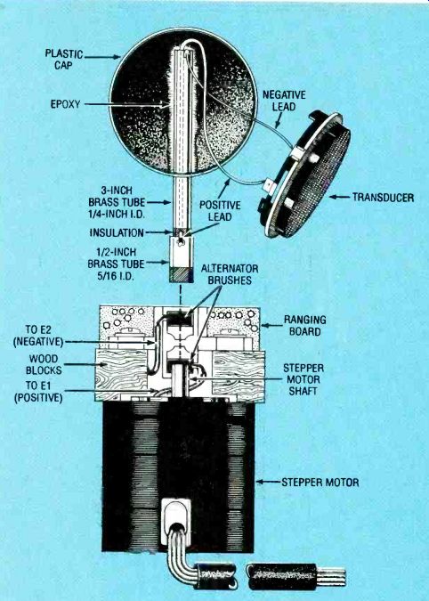
FIG. 7--TWO ELECTRICAL CONTACTS must be maintained while the transducer
rotates. Here's how that was done on the prototype.
Drill a hole the same diameter as the long tube in the side of a plastic jar lid, as close as possible to inner top surface of the lid. Slide the lid onto the end of the tube farthest from the outer ring, and glue it in place. (Sanding the mating plastic and brass surfaces will allow the glue to hold better.) Solder one of the two clips provided with the ultrasonic transducer to the wire from the outer ring, and slide the clip onto the inside terminal ( + ) of the transducer. Solder another insulated wire to a point on the longer brass tube inside the lid. Solder the other end of that wire to the unused transducer clip, and slide the clip onto the outside terminal (-) of the transducer. Pay attention to polarity! Mount the transducer in the lid by surrounding it with a strip of foam rubber for a snug fit. The longer tube can now be bonded to the shaft of the stepper motor with epoxy.
Automotive alternator brushes make excellent contacts for linking the ranging board to the long tube and ring.
You can buy the brushes at most automotive stores for a few dollars, or a complete brush assembly with mounting hardware for less than $10. There are many different styles of brushes and assemblies, and some are easier to adapt than others.
Choose one that has a convenient size and shape to work with. You might need to file some parts of the assembly, or remove unneeded metal fittings. The assembly can be mounted to the stepper motor with small wood blocks.
Complete the connections by running wires from the brushes to the ranging board. Again, observe the correct polarity! The longer tube is ground, and it connects to the E2 terminal on the ranging board (the black wire with the red stripe). The outer ring is positive, and it connects to the E1 terminal (the plain black wire). Although the ranging board produces 400 volts when operating, it does so only in brief pulses of current low enough so that it is not dangerous-but it will give you a mild shock if you touch the right place.
The ranging board can be glued to the wood blocks or the brush assembly. If the 300 µF capacitor installed across J1 pins 1 and 9 interferes with mounting the ranging board, move the capacitor to the front of the board on U1 between pin 16 (GND) and pin 5 (V +).
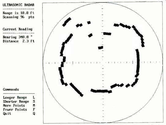
FIG. 8--THE RADAR IN OPERATION. The ultrasonic "RADAR" can
detect and display objects from about 6 inches to 35 feet. Here
the maximum range has been set to 15 feet.
ULTRASONIC RADAR
Range is 10.0 ft
Scanning 96 pts
Current Reading Bearing 348.8 °
Distance 2.3 ft
Commands Longer Range L Shorter Range S More Points M Fewer Points F Quit Q
Software
Two programs were written for the ultrasonic radar, and both are contained in the self-un-archiving ZIP file (EXPERI.EXE) on the Electronics Now BBS. Both programs were written in Microsoft's Quick-BASIC. DISTANCE.BAS is a simple distance-measurement program. It pulses the rangefinder several times per second and reports the distance measured with 0.01-inch resolution over a range from about 6 inches to 35 feet. You can calibrate the unit for the speed of sound at your location by placing a flat object, such as a box, a carefully measured distance from the transducer. When you run the program, it will report the distance it measured, based on the default value for the speed of sound (1100 feet per second). If the reported distance is more than the actual distance, decrease the speed of sound parameter by pressing the "1" key.
It decreases the parameter by 10 feet per second. Pressing the "2" key decreases the speed by one foot per second. If the reported distance is less than the actual distance, increase the speed of sound parameter. Pressing the "4" key increases the parameter by 10 feet per second; pressing the "3" key increases the parameter by 1 foot per second.
-------------
SOURCES
The following parts are available from Fascinating Electronics, PO Box 126, Beaverton, OR 97075. For VISA or MasterCard orders call 1-800-683-KITS, weekdays 10:00 AM to 5:00 PM, Pacific Time.
Ultrasonic transducer, ranging board, cable, connector, and capacitors--$69.90
PC compatible or Macintosh software on either 5.25or 3.5-inch disk (please specify machine and format)--$9.90
Experimenter in kit form--$149.90
Assembled and tested Experimenter $199.90
9-volt 500 mA power supply $11.90
There is a limited quantity of the 4.25-volt, 1.7-amp, 200-step-per-revolution, surplus/used stepper motors available (includes series resistors) $14.90 Please include $3.40 for shipping and handling with your order. Foreign orders, please inquire for prices and availability.
----------------
You can include the speed–of-sound parameter you determined in the radar program to make it more accurate. The speed of sound parameter, and other initialization parameters, are read by the radar program from the file RADAR.DAT. The graphical radar program is easy to use. For a high-resolution color radar display, your computer will need EGA or VGA display electronics and a color monitor. If your computer just has CGA, the radar program will provide a lower resolution black and white display, as shown in Fig. 8.
Each rangefinder distance reading is plotted on the display in real-time. It provides scale information with bars of different colors and lengths drawn along the axes. Tens of feet are marked by long green bars; five-foot marks are red; and one-foot marks are short green bars.
Half-foot marks are short black bars, and quarter-foot marks are green dots.
On the left side of the display the program reports the present range values and the number of scanning points in each revolution. The bearing and distance values are updated for each rangefinder measurement.
Listed at the lower left are the commands you can give the program while it is running. Pressing the "L" key increases the displayed range (up to 35 feet). Pressing the "S" key decreases the displayed range (down to 5 feet). Pressing the "M" key causes the drive motor to scan more points per revolution (up to the resolution of the drive motor selected). Pressing the F key reduces the points in the can (to a minimum of 12, depending on motor resolution). You can modify RADAR.DAT ext file with any text editor or word processor. Each parameter is followed by a comment bout its function. The first parameter allows you to select a monochrome display, which is useful if you want to make a hard copy by pressing the print-screen key. (You also must set p the graphics print driver in DOS.) The speed-of-sound value you determined is set next. The next few parameters specify the stepper motor used; the drive type, steps per revolution for your motor at that drive type, and the motor speed in milliseconds-per-step. The last parameters adjust for the characteristics of he rangefinder and radar display. You can leave these values t their defaults. Be sure to save any changes that you make to RADAR.DAT as a text or ASCII le.
The QuickBASIC source code or the radar program can be downloaded from the Electronics Now BBS. However, it is also available on disk, along with the DISTANCE program, n both source and executable form from the source given in his article. Versions for the Macintosh computer are also available.
The relative difficulties of converting the radar program to turn on other types of computers will depend on how closely the version of BASIC on that machine resembles Microsoft's Quick BASIC. You can contact Fascinating Electronics (see supplier list) to determine if anyone has already performed he conversion for your type of computer. If so, the program will probably be available to you at little cost. If not, you might want to consider making your translation available to other hobbyists through Fascinating Electronics.
Also see: SCREEN Printing PC BOARDS