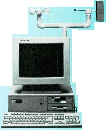
Build a computer-controlled weather-monitoring station and become an expert on local weather conditions.
By RONALD M. JACKSON
THE BAROMETRIC PRESSURE IS falling rapidly, dropping by almost an inch of mercury in 12 hours. A big storm is on the way. Relative humidity begins a slow rise as cloud cover increases. The wind rapidly picks up speed. Gusts peak at over fifty miles an hour. The relative humidity increases sharply and air temperature drops. Steady heavy rains begin, sending the relative humidity over 96 %. The downpour lasts an hour. Over one inch of rain falls in that time. The wind direction changes from southwest to northwest as the storm front passes. Front passage is confirmed as the barometric pressure begins a slow rise. As the cold air scours out the warm, the temperature drops ten degrees. With the weather station presented in this article, your computer can monitor every facet of the storm.
A weather monitor
The weather affects everyone. But instead of just being a source of rained-out picnics, the weather can be a source of endless fascination. Driven by the forces of heat from the sun and the rotation of the earth, modified by both continental and local topology, the weather is a constantly changing panoply of winds, heat, moisture, and pressure. This month's project is a professional caliber instrument that will to help you unlock the secrets of the weather.
This computerized meteorological station uses the Experimenter (presented in the July and August issues of Electronics Now) to link weather instruments to your computer.
Any PC-compatible computer with CGA, EGA or VGA graphics can be used. A Macintosh software version is in development, and may be available by the time you read this. Because of the extensive measurement capabilities built into the Experimenter, the electronics for this project are relatively simple.
With the standard software package, this project can measure and display a wide range of weather conditions with great accuracy. However, a professional version of the software can be purchased. It permits measurements to be stored on disk so that they can be recalled and displayed graphically on the screen or printed on laser or dot-matrix printers. Minute–by-minute information can be recorded for 24-hour periods to aid in weather forecasting.
Hourly data and daily minimum/maximums are stored for historical analysis.
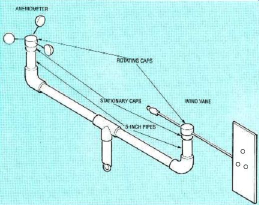
FIG 1--THE ANEMOMETER AND WIND VANE mount on a single PVC pipe assembly.
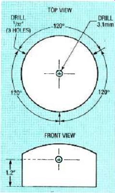
FIG. 2--ANEMOMETER ROTATING CAP. Drill three 5 1/2-inch holes, evenly
spaced, in a 2-inch PVC end cap, 1.2 inches up from the open end. Drill
one 3.1 mm hole in the exact center of the top of the cap.
By using the alarm capabilities in the software, along with the relay and eight driver outputs on the Experimenter, you can program the station to take actions based on weather conditions. Perhaps you would like to automate a greenhouse so that when the temperature drops too low or rises too high, an exhaust fan or heater will be activated; if the relative humidity dropped too low, a mist system or lawn sprinklers could be triggered.
Because we've already covered the electronics in the Experimenter, most of this article is mechanically oriented. Let's get right down to building the mechanical elements of the weather station.
Construction
You might want to build only part of the weather station because the software can be easily configured for the particular sensors you choose to include.
You can have a system working with as little as one instrument.
Instruments can be purchased completely assembled and tested, or you can build them yourself. Complete kits of pre-drilled, ready-to-assemble parts are also available for quick and easy construction. For those with a well-equipped shop, kits with only the hard-to-find parts are also available.
All instruments can be calibrated to professional levels of accuracy. Calibration procedures that do not require special equipment are included for each instrument.
The electronics are simple enough to be added in the wiring-grid area on the Experimenter. For those who dislike point-to-point wiring, or want the most reliable system possible, a circuit board can be made from the foil patterns that will be provided next month, or one can be purchased from the kit supplier.
Wind and rain Which way is the wind blowing? Is it a gale or a zephyr? How much rain fell last night, and how much fell in that last downpour? The wind vane, anemometer, and rain gauge are easy to assemble. If you choose to assemble those instruments from the kits of already drilled parts, you can skip the sections on preparing materials. But, if you have a well equipped shop and know your way around a hardware store, you can use the hard-to-find parts kit and buy the other components locally.
The wind vane and anemometer are mounted on a single assembly composed mostly of PVC pipes and fittings, as shown in Fig. 1.
Building the anemometer
The anemometer consists of a rotating assembly (including wind cups and a rotating cap), and a stationary base. The rotating cap turns a stainless steel shaft which is supported vertically on a sharp pin, and horizontally by a sintered bronze bushing. Rotation is detected by a magnetic switch. If you are using the complete kit you can skip this section on preparing materials and go right to the section on assembly.
The rotating and stationary caps are made from schedule 40 PVC end caps, available at most plumbing supply stores. Be sure to use only schedule 40 PVC pipe and fittings; lighter grades might not hold up well in cold or rough weather.
Figure 2 shows the construction of the rotating cap.
Drill three 5/32-inch holes evenly spaced around a 2-inch PVC end cap, 1.2 inches from the open end of the cap. Drill a 3.1 millimeter hole through the exact center of the top of the cap.
Be sure that the holes are perpendicular to the cap. If they are not, the anemometer's accuracy will be degraded.
The stationary cap is shown in Fig. 3. Some PVC caps have molding bumps on their outside diameters. If the 1 1/2-inch stationary cap has any that could rub on the inside of the rotating cap, they must be sanded or filed off. The stationary cap requires two holes:
In the exact center of the cap drill a 0.25 cinch hole for the sintered bronze bearing. At 9/16-inch from the center, drill a 5/16-inch hole for the magnetic sensor.
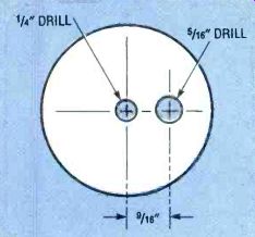
FIG. 3--ANEMOMETER STATIONARY cap. Drill a 1/4-inch hole in the exact
center of the top of a 1 1/2-inch PVC end cap. Drill a 5/16-inch hole
offset 9/16-inch from the center of the top.
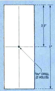
FIG. 4--ANEMOMETER VERTICAL pipe.
Cut a 5-inch long piece of 1 1/2-inch PVC pipe. Drill two 3/32-inch holes on opposite sides of the piece, 21 inches from each end.
The stationery cap mounts on a 5-inch piece of 1 1/2-inch diameter schedule 40 PVC pipe. Drill two 3/32-inch holes on opposite sides of the PVC pipe, 2.5 inches from each end. See Fig. 4. The wind cups are hemispheres of tough, pliable plastic (actually non-perforated Wiffel balls cut in half), with holes on opposite sides made near the cut edge. The pieces of the anemometer are now ready for assembly.
For best appearance and longest life, use only stainless-steel hardware on the anemometer.
The wind cups are fastened to the rotating cap with 4-inch 8-32 machine screws. See Fig. 5. Slip a lock washer and a flat washer on a 4-inch screw, … push the screw through … the holes into a wind eon another lock … thread two nuts ?' on the screw. Slip lock washer, then screw through the o, and out of the wind … another lock washer … screw and thread another on the screw. Move and tight the nuts to clamp the wind cut in place. Adjust the nuts so that the wind cup is round. Repeat for the other two wind cups.
Now attach the wind cups to the rotating cap. Thread a nut about 1/2-inch on the screw, then slide on a lock washer. Thread the screw into one of the holes in the side of the rotating cap.
On the inside of the cap, slip on a lock washer and then thread a nut onto the screw. Adjust the inside nut so it is flush with the
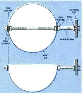
FIG. 5--ATTACHING THE WIND CUPS. The wind cups secure to the rotating
cap with 4-inch long machine screws.
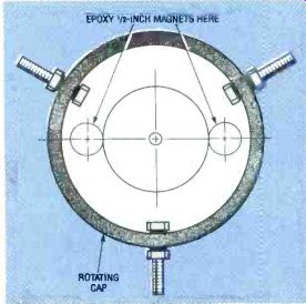
FIG. 6--ANEMOMETER MAGNETS. Two 1/2-inch diameter magnets must be
epoxied under the top of the rotating cap.
[…]
Gently tap the bronze bead into the center hole of the stationary cap, from the inside on the cap outward. The flange on the bearing should be pressed flush against the inside surface of the cap. The fit should be tight enough that the bearing is held solidly. Using the plastic nuts provided, secure the magnetic switch in the second hole so that it extends 3/8-inch above the top of the stationary cap.
See Fig. 7.
Cut a 1 1/2-inch long piece from a one-by-two cedar board (which actually measures about ¾-by 1½-inch). This will form part of the support for the rotating assembly. Sand or file the corners of the wood block as necessary so that it fits snugly into the pipe. Slip the wood block into the pipe, and slip the stationary cap lightly in place.
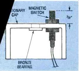
FIG. 7--THE BEARING AND MAGNETIC switch install in the stationary
cap as shown here.
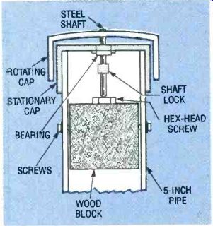
FIG. 8--THE ANEMOMETER SECTIONS go together as shown here.
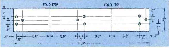
FIG. 9--WIND VANE TAIL. This can be made from aluminum flashing, available
at hardware stores.
Slip the stainless steel shaft through the brass bearing and press it lightly into the wood to make a small indentation. Remove the rotating assembly, stationary cap, and the wood block. Install a No. 10 1/2-inch screw at entation in e end of the t will rest in . n top of theing assembly ary cap, slide a o the stainless to about 1/2-inch … bushing), and .lace. This will preting assembly from of the stationary cap wind. Apply a light f oil to the stainless t and a dab of lithium n the hex-head screw h the bearing is impregnated with oil, this will help to reduce friction further.
Push the wood block back into the tube. Align the 3/4-inch sides of the block with the 3/32-inch holes in the side of the 5inch pipe. The stationary cap will mount on the end of the tube nearest the hex-head screw on the wood block. Slip the magnetic switch wires out through the tube through the large space along the side of the wood block. Grasping the sides of the stationary cap only (do not press down on the rotating cap), force the stationary cap solidly onto the tube.
By reaching through the open end of the tube, adjust the vertical position of the wood block so that the point of the shaft supports the rotating assembly.
Rotate the assembly to verify that the magnets do not hit the magnetic switch, and that the nuts do not drag on the stationary cap. The anemometer should turn easily when you blow on the cups. If not, determine the cause of the drag. Rotate the assembly while using an ohmmeter to verify that the magnetic switch opens and closes. Secure the wood block in position with two No. 4 1/2-inch sheet-metal screws, threaded through the 3/32-inch holes in the tube. The anemometer is now finished.
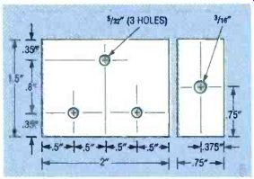
FIG. 10--TAIL MOUNTING BLOCK. The wind vane tail mounts on a wood
block.
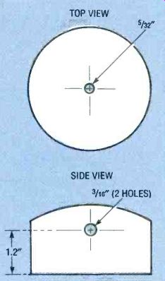
FIG. 11--WIND VANE ROTATING CAP. Make the wind vane rotating cap from
a 2-inch PVC end cap.
Building the wind vane Like the anemometer, the wind vane consists of a rotating assembly (including the tail, counter balance, and rotating cap), and a stationary base.
Wind direction is translated into two voltages by a dual-wiper potentiometer. The rotating assembly is fastened to a ball bearing unit, press fit into the stationary cap. A length of flexible tubing links the rotating assembly to the potentiometer shaft.
If you purchase a complete kit, you can skip this section on preparing materials and go right to the assembly. To prepare the tail, cut a 3-by-17.6-inch piece of thin-gauge aluminum. Aluminum flashing, available at many hardware stores, has the right thickness.
Punch nine 5/32-inch holes in the aluminum as shown in Fig. 9. Fold it along the lines indicated in the figure, both toward the same side. The tail in the kit is anodized for improved corrosion resistance; if you are making your own, and you live in a wet climate, you might want to paint it. Painting the aluminum will increase the tail's weight, so you might need to use a larger counterweight.
The tail mounts on a wood block with the measurements shown in Fig. 10. Use a durable, moisture-resistant wood such as Cedar. Drill three 5/32-inch diameter holes in the face of the block, and one 3/16-inch diameter hole down the length of the block as shown in the figure.
Make the counterweight for the wind vane from a 1 ½ ounce, egg-shaped fishing weight. Drill a 3/16-inch diameter hole through the weight lengthwise so that it will slide onto a No. 10 screw. Since lead is a soft metal with a low melting point, use a fresh drill bit, a low drill speed, and a dab of oil to avoid melting the lead.
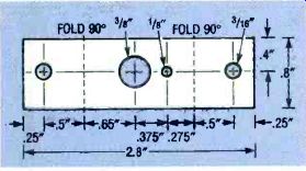
FIG. 12--POTENTIOMETER MOUNTING bracket. Make the potentiometer mounting
bracket from a 0.8- by 2.8-inch piece of 0.032-inch thick aluminum.
As with the anemometer, the parts for the wind vane are made from schedule-40 PVC. Make the rotating cap from a 2-inch PVC end cap as shown in Fig. 11. Drill a 5/32-inch diameter hole in the exact center of the top of the cap. Drill two 3/16-inch diameter holes on exactly opposite sides of the cap, 1.2inches up from the open end of the cap. Be sure that these holes are perpendicular to the cap.
Make the stationary cap from a 1 1/2-inch PVC end cap. Sand or file off any molding bumps that might rub on the inside of the rotating cap. Drill a 39/64-inch hole in the exact center of the cap. A 5/8-inch outside diameter, 1/4-inch inside diameter flanged ball bearing unit installs in this hole. Using a reaming bit, enlarge the hole to a few thousandths under 5/8-inch to permit press-fitting of the ball bearing unit.
Cut a 5-inch length of 1 1/2-inch PVC pipe. Drill two 5/32-inch holes on opposite sides of the pipe, 2.5 inches from one end; the potentiometer mounting bracket will bolt inside through these holes. The holes are drilled in the same positions as in the anemometer tube, but the drill bit is larger.
Construct the potentiometer mounting bracket from a 0.8inch by 2.8-inch piece of 0.032-inch thick aluminum. Punch one 3/8-inch diameter hole, two 3/16-inch diameter holes, and one 1/8-inch diameter hole as shown in Fig. 12. Then make two 90° folds in the bracket in the indicated positions. It is essential that the folds be made at exactly the same distance from the 3/8-inch potentiometer mounting hole. If the distances are wrong, the potentiometer will be off center, which will degrade the sensitivity of the wind vane. The pieces of the wind vane are now ready to be assembled. Be sure to use only stainless-steel machine screws and other hardware on the wind vane.
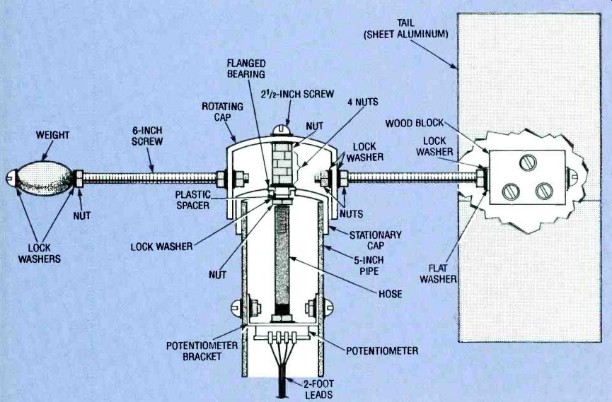
FIG. 13--THE WIND VANE SECTIONS go together as shown here.
Use Fig. 13 as a visual aid for the following procedures. Slip a lock washer and a flat washer on a 6-inch long No. 10-24 screw, then slide the screw through the 3/16-inch diameter hole running the length of the wood block. Slip another flat washer and lock washer on the screw, and secure with a hex nut.
Thread a hex nut about 1/2-inch on the screw, slip on a lock washer, then run the screw into one of the 3/16-inch holes in the side of the rotating cap. Slip a lock washer and thread on a hex nut so that it is flush with the end of the machine screw. Rotate the screw so that the wood block is vertical with the two holes below and the single hole above, then securely tighten the hex nut against the outside of the rotating cap.
Slip a lock washer down the length of the other 6-inch screw.
Slide the lead weight on next, followed by another lock washer. Thread a hex screw down to the lead weight and tighten it.
Thread another hex nut about 1-inch on the screw, slip on a lock washer, and run the screw into the 3/16-inch hole opposite the tail. Slip on a lock washer then thread on a hex nut. The hex nuts will be adjusted later on so that the lead weight exactly balances the tail.
Use a vise to press the ball bearing unit into the stationary cap from the top side. Place blocks of wood on either side of the center hub so that the jaws of the vise press only on the flange and do not put pressure on the ball bearings. Press in the flange flush with the outside of the cap.
Slip a lock washer on a 2 1/2 inch No. 8-32 machine screw, and thread the screw down the 5/32-inch hole in the top of the rotating cap. Slip another lock washer on the screw, thread on a hex nut, and tighten it securely. Thread another four hex nuts on the screw and tighten.
Slip a lock washer on the screw, then push the plastic spacer on.
Slide the stationary cap with the bearing in it over the screw and onto the plastic spacer. Slip on a lock washer, thread on a hex nut, and tighten it. Verify that the rotating assembly turns freely, without rubbing on the stationary cap.
Now slip the tail section over the wood block and align the three holes. Secure it in place with three 1-inch No. 6-32 machine screws. Be sure to use lock washers under the screw heads and hex nuts.
Then the wind-vane assembly sideways, and run the counter weight screw in or out as necessary to precisely balance the weight of the tail. When balanced, remove the stationary cap from the rotating assembly and tighten the hex nuts on the counter-weight screw to secure it in position.
PARTS and KITS
The following kits are available from Fascinating Electronics, PO Box 126, Beaverton OR 97075-0126. You can call 1-800-683-KITS with VISA and Master-card orders, catalog requests, and technical questions 24 hours a day, 7 days a week. Please include $3.40 for US shipping and handling with any order. Canadian shipping and handling is $5.00, with payment in US dollars. Foreign orders, please inquire for prices and availability.
NOTE: The following kit descriptions are also to be used as parts lists. If you are gathering the parts together on your own. you'll need all parts listed under the "Complete Kit" headings to build each unit.
ANEMOMETER
Complete kit-$37.50
(3) 3-inch diameter plastic hemispheres, punched
(1) oil-impregnated bronze bearing, 0.126 x 0.252 x 3 1/2-inch, flanged
(1) stainless-steel shaft, 0.1247x 3-inch, pointed on one end
(1) shaft lock, 1/8-inch
(1) magnetic switch, 1.5 x 5/16-inch, with hex nuts
(2) disk magnets, 1/2-inch diameter
(1) 2-inch schedule-40 PVC cap, precision drilled
(1) 1 1/4-inch schedule-40 PVC cap, precision drilled
(1) 1 1/2-inch schedule 40 PVC pipe, 5 inches long, drilled
(1) wood block, ¾ x 1 1/2x 1 1/2inches
(2) No. 4 stainless-steel sheet-metal screws, 1/-inch long
(3) 8-32 stainless-steel machine screws, 4 inches long
(15) 8-32 stainless-steel hex nuts
(3) No. 8 stainless-steel flat washers
(18) No. 8 stainless-steel lock washers, internal tooth
(1) No. 10 stainless-steel hex-head sheet-metal screw, 1/2-inch
Hard-to-find parts
kit-$17.50
(3) 3-inch diameter plastic hemispheres, punched
(1) oil-impregnated bronze bearing, 0.126 x 0.252 x 3-inch, flanged
(1) stainless-steel shaft, 0.1247x 3-inch, pointed on one end
(1) shaft lock, 1/8-inch
(1) magnetic switch, 1.5 x 5 /,6-inch, with hex nuts
WIND VANE
Complete kit-$39.90
(1) dual-wiper potentiometer
(1) ball bearing, 1/4-inch ID, 5 1/2-inch OD, flanged
(1) plastic spacer, 1/2-inch ID, 1/4-inch OD
(1) tail fin, anodized aluminum, punched and folded
(1) potentiometer mounting bracket, punched and folded
(1) 1 1/2-oz. lead egg-shaped fishing weight, drilled
(1) 2-inch schedule-40 PVC cap, precision drilled
(1) 1 1/2-inch schedule-40 PVC cap, precision drilled
(1) 1 1/2-inch schedule-40 PVC pipe, 5 inches long, drilled
(1) wood block, ¾ x 1 1/2x 2 inches, drilled
(1) hose, 1 1/2 inches long, 1/8-inch ID
(3) 6-32 stainless-steel machine screws, 1-inch long
(3) 6-32 stainless-steel hex nuts with lock washers
(6) No. 6 stainless-steel flat washers
(3) No. 6 stainless-steel lock washers
(1) 8-32 stainless-steel machine screw, 2 1/2 inches long
(2) 8-32 stainless-steel machine screws,'/ inch long
(6) 8-32 stainless-steel hex nuts
(2) 8-32 stainless-steel hex nuts with lock washer
(6) No. 8 stainless-steel lock washers
(2) 10-24 stainless-steel machine screws, 6 inches long
(7) 10-24 stainless-steel hex nuts
(2) No. 10 stainless-steel flat washers
(8) No. 10 stainless-steel lock washers Hard-to-find parts kit$15.50
(1) dual-wiper potentiometer
(1) ball bearing, 1/4-inch ID, 5 1/2-inch OD, flanged
Assembled and tested anemometer & wind vane on "T" mount with 100 foot cable and modular connector $159.90
Attach 2-foot wires to the four terminals on the dual-wiper potentiometer. Label the wires 1 through 4 from left to right. Fasten the potentiometer to its bracket with its 3/8-inch hex nut and lock washer. The potentiometer shaft should point in the direction opposite that of the bracket flanges.
Run a 1 1/2-inch long piece of 1/8-inch inside-diameter hose about 0.5-inch onto the No. 8 screw in the rotating assembly.
Push the other end of the hose down the length of the potentiometer shaft. Grasping the assembly carefully, press the stationary cap onto the 5-inch pipe while watching for the holes in the potentiometer bracket to line up with the holes in the side of the pipe. It might be necessary to remove the assembly and adjust the position of the hose on the screw and potentiometer shaft to get the bracket holes to line up when the assembly is pushed fully in place. Install two 1/2-inch No. 8-32 machine screws, with lock washers, through the holes. Use hex nuts with captive lock washers inside the tube to secure the bracket to the screws.
The wind vane is now finished.
------------
RAIN GAUGE
Complete kit-$29.90
(1) magnetic switch, 1.5x 5/,s-inch with hex nuts (Hamlin Mfg)
(1) disk magnet, /-inch diameter (1) downspout adapter, 2x 3x 3inct-es, drilled (1) measuring spoon, Rubbermaid #2235 '/2 TBSP, drilled (1) plastic funnel, 8-inch diameter (spout smaller than ' /c inch in diameter) (1) 3-inch diameter schedule-40 PVC pipe, 3 inches long, drilled (1) brass rod, '/32-inch diameter, 2.75 inches long (2) No. 6 stainless-steel sheet-metal screws, 1/2-inch long (2) cocktail straw sections, 3/4-inch long Hard-to-find parts kit-$5.90 (1) magnetic switch, 1.5x 5/,s-inch with hex nuts (Hamlin Mfg)
Assembled and tested rain gauge with 50-foot cable and modular plug-$59.90
SENSORS
Temperature sensor kit-$15.90
(5) _M334Z current sources (National Semiconductor)
(5) 2.26-kilohm, 1% resistors
(5) 0.01 µF capacitors
(1) dual-wall heat-shrink tube, 3/16-inch diameter, 6 inches long
(1) DB25M connector, with shell Humidity sensor kit-$29.90
(2) humidity sensors (Philips 2322 691 9001)
(2) 555 timer ICs
(2) 0.1 µF disk capacitors
(4) 1 megohm, 1% resistors
(1) dual-wall heat-shrink tube, 1/2-inch diameter, 3 inches long
Assembled and tested temperature and humidity sensors--$99.90
Includes:
One humidity sensor and one temperature sensor on a 50-foot cable with a mocular plug
Four temperature sensors and one humid sensor connected to a DB25 connector with shell One humidity sensor and one temperature sensor on a 10-foot cable One temperature sensor on a 50-foot cable Two temperature sensors on 30-foot cables (Custom cable lengths are available, inquire for pricing.)
-----------
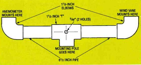
FIG. 14--WIND INSTRUMENT MOUNTING. A simple, yet sturdy mount for
the wind instruments can be made from PVC pipe.
----------
CONDITIONING BOARD AND BAROMETER
Signal conditioning board and barometer kit-$49.90
(1) signal conditioning board
(2) TLC2274 op-amps (National Semiconductor)
(1) 74HC393 dual counter (Harris)
(1) AD621 instrumentation amplifier (Analog Devices)
(1) SCC15A pressure sensor (Sensym)
(1) 20 kilohm multiturn potentiometer
(16) 0.1 uF disk capacitors
(2) 1 megohm, 5 %,1/4-watt resistors
(2) 10-kilohm, 5 %, 1/4-watt resistors
(5) 499-kilohm, 1 %,1/4-watt resistors
(7) 100-kilohm, 1 %,1/4-watt resistors
(1) 1 %, 1/4-watt resistor
(1) 13.7-kilohm, 1 %, 1/4-watt resistor
(1) 12.7-kilohm, 1 %,1/4-watt resistor
(1) 10.0-kilohm, 1 %,1/4-watt resistor
(1) 2.87-kilohm, 1 %,1/4-watt resistor
(1) 1kilohm, 1%, 1/4-watt resistor
(1) DB25M connector
(3) 6 contact modular jacks
Bare signal-conditioning
PC board only-$19.90
Assembled and tested signal-conditioning board and barometer--$99.90
Includes: Signal conditioning circuitry for all sensors
Both DB25 and modular connectors installed
Barometer that requires calibration to your location
SOFTWARE
Professional version software for PC--$39.90
Professional version software for MAC--$49.90
THE EXPERIMENTER
Experimenter kit--$149.90
Optional analog supply--$4.90
Assembled and tested
Experimenter with analog option $199.90
For more information on the Experimenter, see the July and August 1993 issues.
-------------
Mounting
A simple yet sturdy mount for the wind instruments can be built from two 6 1/2-inch sections of 1 1/2-inch schedule-40 PVC pipe, two 1 1/2-inch 90° elbow fittings, and one 1 1/2-inch "T" fitting (see Fig. 14). Use cement formulated specifically for PVC (available where the pipe is sold) to bond the pieces together. Directions for using the cement are provided on the label; you won't use much, so buy the smallest amount available.
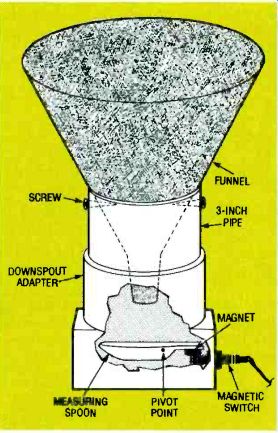
FIG. 15--THE RAIN GAUGE is configured as shown here.
Drill a 5/32-inch diameter hole in the center of both sides of the "T" fitting. Cement the two 6 1/2-inch pipe sections in the arms of the "T" Cement the elbows on the pipe sections, setting the assembly on a table top to make all the connections line up properly. Run a 2 1/2-inch long No. 8-32 machine screw through the hole, and secure it with a hex nut and lock washer. Slip the wind instruments into the two elbows. Run their wires through the pipes and out through the "T." Tie the connecting cable to the No. 8-32 screw, then connect the wires to the wind instruments. An appropriate length of pipe can be fitted to the bottom of the "T" to support the assembly. Run the cable down the inside of the supporting pole, and cement the pole to the "T" Telephone wire is suitable for the cable, and is available in six-conductor cables. Be sure to record which signal connects to which color wire! If you use a flat cable, connect the magnetic switch to the first two conductors, then the four numbered potentiometer wires, in sequence, to the next four conductors.
Building the rain gauge
The rain gauge, shown in Fig. 15, is built around a 2-inch by 3inch downspout adapter. A 3inch diameter PVC pipe connects the downspout adapter to a large funnel. The funnel collects rain water and channels it into a small measuring spoon, which acts as a tipping bucket.
The measuring spoon is hinged and balanced so that when sufficient water collects, the spoon tips, dumping the water. A small magnet mounted on the spoon triggers a magnetic switch each time the spoon tips. With the components specified, the rain gauge has a resolution greater than one hundredth of an inch. If you purchase the complete kit you can skip this section on preparing materials and go right to the section on assembly.
Drill the downspout adapter as shown in Fig. 16. Drill a 5/16-inch diameter hole for the magnetic switch in the middle of the 2-inch wide face of the downspout adapter, 1 inch up from …
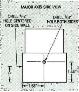
FIG. 16--RAIN GAUGE DOWNSPOUT adapter. A 2-inch by 3-inch downspout
adapter forms the base of the rain gauge.
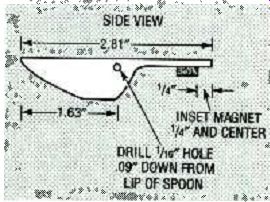
FIG. 17--RAIN GAUGE MEASURING spoon. The measuring mechanism in the
rain gauge uses a ½ tablespoon measuring spoon.
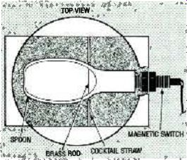
FIG. 18--MEASURING SPOON installation. The top view of the downspout
adapter is shown.
... the bottom. Drill a 1/26-inch diameter hole on each of the 3-inch wide faces, 1.63 inches from the face with the magnetic switch hole, and 1.44-inches up from the bottom.
Cut the excess length off of the measuring-spoon handle as shown in Fig. 17, reducing the overall length to 2.81 inches.
Drill 1/16-inch diameter holes on each side of the spoon's bowl, 1.63 inches from the front edge and 0.09-inch down from the top. Glue the 1/2-inch diameter magnet to the handle of the spoon, 1/4-inch from the end of the handle.
Referring to Fig. 18, cut a 2 3/4-inch long section of 1/22-inch diameter brass rod, and cut two 3/4-inch long sections from a cocktail straw. Cut a 3-inch long section of 3-inch diameter schedule-40 PVC pipe, and drill two 1/8-inch diameter holes on opposite sides of the pipe 0.375 inch from one end.
Using the plastic nuts provided, install the magnetic switch in the 5/16-inch diameter hole in the downspout adapter with the switch's wire leading outside the adapter. Adjust the nuts so that the other end of the switch extends 3/4-inch inside the adapter.
Insert the 2 3/4-inch long brass rod through one of the 1/16-inch diameter holes into the downspout adapter. Slip a 3/4-inch long section of plastic cocktail straw on the brass rod. Then slip the rod through the two holes in the measuring spoon, through the other 3/4-inch long piece of cocktail straw, and into the other 1/16-inch diameter hole in the downspout adapter. The handle on the spoon should rest on the magnetic switch. Seal the holes with the tip of a soldering iron to prevent the brass rod from slipping out.
Insert a 3-inch section of 3 inch diameter schedule-40 PVC pipe into the downspout adapter. Place an 8-inch plastic funnel on top of the PVC pipe. Make sure that the spout on the funnel is centered over the spoon bowl and is perpendicular to the adapter. If the separation from the funnel spout and the bowl of the spoon is too great, trim the 3-inch PVC pipe shorter. Secure the funnel to the pipe with two No. 6 sheet-metal screws through the '/a-inch diameter holes in the pipe.
Next month: That's all we have room for this month. Next month we'll make the electrical connections to the mechanical devices that you should have finished by then.
Also see: Link | --WEATHER STATION (part 2)