by RONALD M. JACKSON
Here comes the rain-let's make sure our weather station is ready for it.
IN LAST MONTH'S ARTICLE. Construction details for an anemometer, wind vane, and rain gauge were described. Now it's time to build the sensors to measure temperature and humidity and complete the weather station. Experimenter's connections to your computer were described in Electronics Now, July and August 1993. This month the weather station's connections to the Experimenter are described.
Air sensors
"It's not the heat, it's the humidity." Although sometimes it's both! But in either case, the weather station has the data you need. Five temperature sensors, with tenth-of-a-degree resolution, provide accurate temperature information. You can place one indoors, one outdoors, one upstairs, one downstairs, and one, perhaps, in the attic or deep freezer.
Two humidity sensors provide inside and outside relative humidity information, with 1% resolution. You might use the information to calculate the heat index, or to monitor conditions in a greenhouse.
Changes in barometric pressure are generally the most useful weather prediction indicators. A falling pressure trend usually means that stormy weather is on the way, while a rising trend portends sunshine. The weather station uses a solid-state pressure sensor to make accurate, stable, high-resolution barometric pressure measurements. Although not possible with the "freeware" program, a professional version of the software permits all weather data to be stored on your computer's hard disk. Graphing features make it easy to see and interpret pressure trends.
The signal conditioning electronics for the temperature and humidity sensors can be wired point-to-point in the wiring grid area on the Experimenter board. With a tight layout, all of the components will fit on the board. However, be aware that every fourth pad on the top and bottom rows of the wiring grid are connected to +5 volts and ground, respectively. Those pads are convenient for supplying power to logic ICs, which have power and ground connections in the standard locations of upper right and lower left.
But you must be careful to avoid inadvertent connections to +5 volts and ground when wiring other circuitry.
As an alternative to point-to-point wiring, you can make your own signal conditioning board using the foil patterns provided here. A high-quality PC board is also available from the source given in the Parts List.
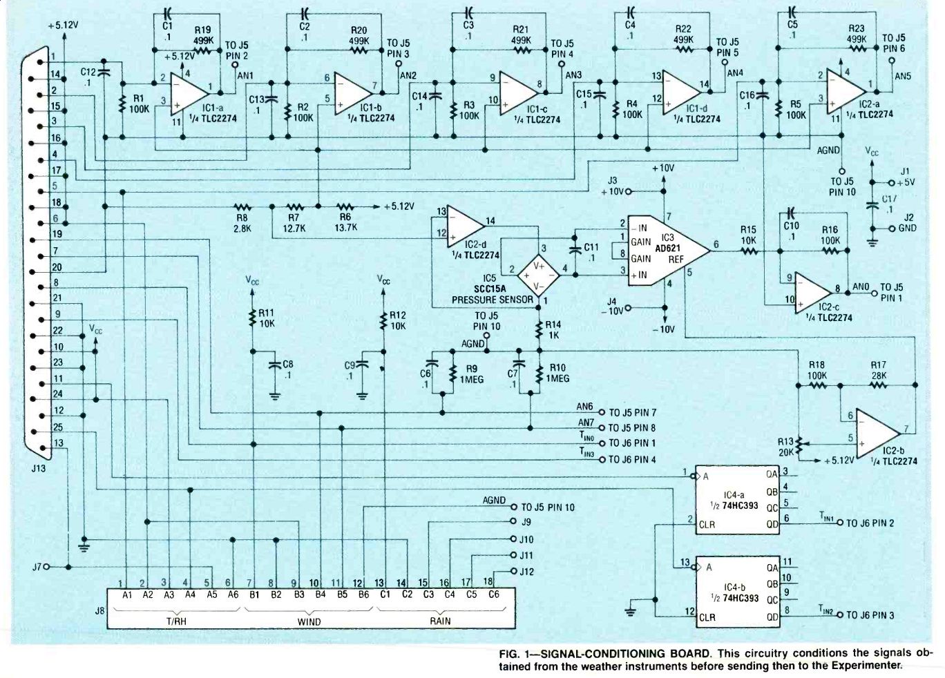
Fig. 1
Signal-conditioning board
None of the meteorological sensors connect directly to the Experimenter. They all require some signal conditioning from the circuitry shown in Fig. 1.
The op-amps, RC filters, and digital prescalers prepare the outputs of various sensors so that the Experimenter can measure them with maximum accuracy. If your Experimenter board does not have the analog supply option. you should add it. Many sensors use the analog inputs, and the optional analog supply will assure the highest accuracy in readings.
The through-hole plated circuit board from the kit supplier, with solder mask and component identification screened on both sides of the board, simplifies construction and improves circuit reliability. Figure 2 is the part-placement diagram. Be sure to clean all residual solder rosin from the board, which can provide leakage-current paths that will cause loss of accuracy in the temperature and pressure measurements.
Inputs and outputs that connect the signal conditioning board to the Experimenter are labeled on the board by silk-screening. These connections must be made to the pads of the same name on the Experimenter. Don't forget to wire the +10 and 10-volt supply inputs on the conditioning board to the power pads of IC5 pins 2 and 6 on the Experimenter board.
Temperature sensors
The weather station temperature sensors are LM334Z current sources. Because their output is current, rather than voltage, the sensors can be located 100 feet or more from the weather station without the series resistance of the wire leads affecting the reading.
Each LM334Z requires a 2.26-kilohm bias resistor for setting the nominal output current. A 0.01-microfarad capacitor across each sensor enhances its stability. Both components can be soldered directly across the leads of the LM334Z as shown in Fig. 3.
The completed temperature sensors should be sealed in a 1.2-inch long piece of 3/16-inch diameter dual-wall heat-shrink tubing. This special tubing has an inner layer of hot-melt gap-filling adhesive; when the tube is heated, the adhesive melts and forms a moisture-proof seal around the leads. If an end of the tube does not close up completely, use a pair of pliers to gently squeeze it shut while the glue is still liquid. Use only a hot-air gun or hair dryer to shrink the tubing, and don't allow the tubing to burn.
----------------------
PART NUMBERS FOR SIGNAL-CONDITIONING BOARD
Resistors
R1-R5, R16, R18100,000 ohms, 1% R613,700 ohms, 1% R712,700 ohms R8-2870 ohms, 1% R9, R10-1 megohm, 5% R11, R1210,000 ohms, 5% R1320,000 ohms, multiturn potentiometer R14-1000 ohms, 1% R1510,000 ohms, 1% R1728,000 ohms, 1% R19-R23--499,000 ohms, 1%
Capacitors
C1 C16-0.1 uF, ceramic
Semiconductors
IC1, IC2
TLC2274 op-amp (National Semiconductor) or equivalent
IC3-AD621 instrumentation amplifier (Analog Devices)
IC474HC393 dual counter (Harris) or equivalent
IC5SCC15A solid-state pressure sensor (Sensym)
Other components
J13-Male DB25 connector
J14-Female DB25 connector
J8 Triple
6-contact modular phone jack
---------------
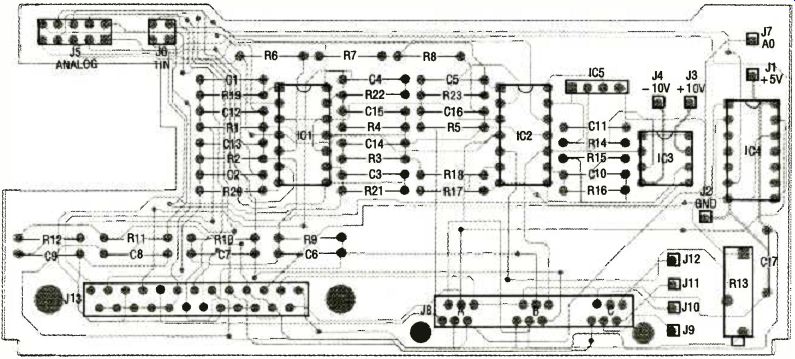
FIG. 2--PARTS PLACEMENT DIAGRAM. Position the parts on the signal-conditioning
board as shown here.
------------------
The male DB-25 connector, J13, on the signal conditioning board makes it easy to connect remotely mounted sensors. Figure 4 shows how the various sensors connect to J13. The positive leads of the temperature sensors connect-with appropriate lengths of wire-to pins 14-18 of J14, a female DB-25 connector that plugs into J13. The output leads of the temperature sensors connect to pins 1-5 of J13. You can also connect the leads from temperature sensor number 5 to pins 1 (output) and 2 ( + V) of J8a, one-third of a triple 6contact modular jack. The modular jack is a more convenient way to connect outdoor sensors.
------------------
PARTS AND KITS
The following kits are available from Fascinating Electronics, PO Box 126, Beaverton OR 97075-0126. You can call 1-800-683-KITS with VISA and Mastercard orders, catalog requests, and technical questions 24 hours a day, 7 days a week. Please include $3.40 for US shipping and handling, with any order. Canadian shipping and handling is $5.00, with payment in US dollars. Foreign orders, please inquire for prices and availability.
NOTE: The following kit descriptions are also to be used as parts lists. If you are gathering the parts together on your own, you'll need all parts listed under the "Complete Kit" headings to build each unit.
-----------------
Once the temperature sensor outputs reach the signal conditioning board, resistors R1R5 convert the current outputs from the five sensors into voltage outputs of about 10 millivolts per degree Kelvin (absolute). The voltage divider R6-R7R8 provides a bias voltage to offset the temperature range from absolute zero to more common ranges. The TLC2274 op-amps IC1a-IC1-d and IC2-a, along with R19-R23, provide a gain of 5, amplifying the temperature-sensor outputs to 50 millivolts per degree Celsius. Capacitors C1-C5 and C12-C16 provide low-pass filtering to remove electrical noise from the temperature readings.
Humidity sensors
Relative humidity is the ratio of the water vapor in the air to the maximum amount of water vapor that the air can hold at the ambient temperature and pressure. It is expressed as a percentage. The humidity sensors used here are capacitors whose values change in proportion to the humidity level. A timer circuit converts the capacitance value to a frequency that is prescaled and then measured by the Experimenter.
The circuit that converts the capacitance of the sensor into a frequency must be located very close to the sensor so that stray capacitance from long lead wires has no effect on humidity readings. However, once converted into a frequency, the signal can be sent over long wire runs back to the Experimenter without being affected.
As indicated in Fig. 4, humidity sensors 1 and 2 get power (+ 5 volts) from pins 10 and 24, respectively, of the DB-25 connector J13. Ground connections are provided on pins 23 and 12. Humidity inputs go to pins 11 and 25. The signal-conditioning board also provides connections for humidity sensor 2 on pins 3-6 of modular jack J8-a. That allows you to connect outdoor temperature and humidity sensors to the signal-conditioning board with a single 6conductor phone cable and modular plug.
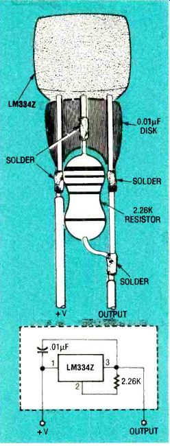
FIG. 3 TEMPERATURE SENSOR. The LM334Z is used as a current output
temperature sensor. A 2.26-kilohm bias resistor and 0.01 µF capacitor
are soldered directly to the leads of the device (see text).
Simple 555 timer circuits convert the capacitance of the humidity sensors to frequency.
The frequency outputs then go to IC4, a 74HC393 dual divider located on the signal-conditioning board. The 74HC393 pre-scales the outputs (through a divide-by-16 operation), and sends the results to the timer inputs TIN1 and TIN2 on the Experimenter.
The circuit that does the frequency conversion can be wired directly on the 555 timer as shown in Fig. 5. Solder a 1 megohm, 1% resistor between pins 7 and 8 on the bottom of the 555 timer. Solder another 1 megohm, 1% resistor between pins 7 and 2, and continue the wire from pin 2 to pin 6. Solder a 0.1 microfarad disc capacitor between pins 1 and 8, and bend the capacitor over so that it rests on the top side of the 555.
If a humidity sensor and a temperature sensor will share a modular-plug connection to J8a, the first two conductors in the cable are used by the temperature sensor, and the next four by the humidity sensor.
--------------------
ANEMOMETER
Complete kit-$37.50 (3) 3-inch diameter plastic hemispheres, punched
(1) oil-impregnated bronze bearing, 0.126x 0.252x 4-inch, flanged
(1) stainless-steel shaft, 0.1247x 3inch, pointed on one end
(1) shaft lock, 1/2-inch
(1) magnetic switch, 1.5x 5 /,s-inch, with hex nuts
(2) disk magnets, 1/2-inch diameter
(1) 2-inch schedule-40 PVC cap, precision drilled
(1)1 1/2-inch schedule-40 PVC cap, precision drilled
(1) 1 1/2-inch schedule 40 PVC pipe, 5 inches long, drilled
(1) wood block, 3/4x 11 x 1 ½ inches
(2) No. 4 stainless-steel sheet-metal screws, 1/2-inch long
(3) 8-32 stainless-steel machine screws, 4 inches long
(15) 8-32 stainless-steel hex nuts (3) No. 8 stainless-steel flat washers (18) No. 8 stainless-steel lockwashers, internal tooth (1) No. 10 stainless-steel hex-head sheet-metal screw, 1/2-inch Hard-to-find parts kit-$17.50 (3) 3-inch diameter plastic hemispheres, punched (1) oil-impregnated bronze bearing, 0.126x 0.252x 3/8-inch, flanged (1) stainless-steel shaft, 0.1247x 3inch, pointed on one end (1) shaft lock, 1/2-inch (1) magnetic switch, 1.5x 5/6-inch, with hex nuts
-------------------
WIND VANE
Complete kit-$39.90 (1) dual-wiper potentiometer (1) ball bearing, 1/4-inch ID, %-inch OD, flanged (1) plastic spacer, 1/2-inch ID, 1/4-inch OD (1) tail fin, anodized aluminum, punched and folded (1) potentiometer mounting bracket, punched and folded (1) 1 1/2-oz. lead egg shaped fishing weight, drilled (1) 2-inch schedule-40 PVC cap, precision drilled (1)1 1/2-inch schedule-40 PVC cap, precision drilled (1) 1 1/2-inch schedule-40 PVC pipe, 5 inches long, drilled (1) wood block, 3/4x 1 ½ x 2inches, drilled (1) hose, 11 inches long, 1/2-inch ID (3) 6-32 stainless-steel machine screws, 1-inch long (3) 6-32 stainless-steel hex nuts with lockwashers
(6) No. 6 stainless-steel flat washers (3) No. 6 stainless-steel lockwashers
(1) 8-32 stainless-steel machine screw, 21/2 inches long (2) 8-32 stainless-steel machine screws, Y2 inch long (6) 8-32 stainless-steel hex nuts (2) 8-32 stainless-steel hex nuts with lockwasher (6) No. 8 stainless-steel lockwashers (2) 10-24 stainless-steel machine screws, 6 inches long
(7) 10-24 stainless-steel hex nuts
(2) No. 10 stainless-steel flat washers
(8) No. 10 stainless-steel lockwashers Hard-to-find parts kit-$15.50
(1) dual-wiper potentiometer
(1) ball bearing, 1/4-inch ID, 3/8-inch OD, flanged
Assembled and tested anemometer & wind vane on "T" mount with 100 foot cable and modular connector--$159.90
---------------------
A humidity sensor's converted frequency output can interfere with the temperature signal if the two signals are conducted in the same cable. For that reason, digital output Ao from the Experimenter can be used to turn the humidity sensor off when temperature readings are taken. The Ao signal is routed to pin 13 of J13 and to pin 6 of J8a, which lets the sixth wire in the telephone cable connect the AO line to pin 4 of the 555 assembly. If a humidity sensor does not share a cable with a temperature sensor, jumper pin 4 of the 555 assembly to the + 5-volt supply at pin 8.
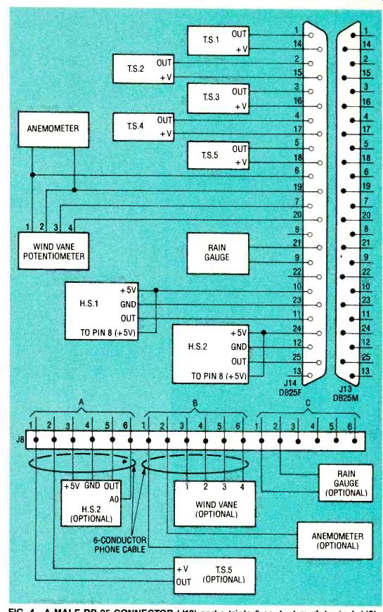
FIG. 4--A MALE DB-25 CONNECTOR (J13) and a triple 6contact modular
jack (J8), mounted on the signal-conditioning board, allow easy
hookup of remotely located sensors.
Attach three or four leads to the 555 timer assembly depending on whether or not it will be sharing a cable with a tempera-ture sensor. (Remember to jumper pin 4 of the 555 to pin 8 if only three leads are to be used.) Use color-coded cabling or label the wires.
Slip a 1 1/4-inch long piece of 1 1/2-inch diameter dual-wall heat-shrink tubing over the 555 timer assembly, and then solder the humidity sensor to pins 6 and 8 of the 555. Its polarity is unimportant.
Use a hot-air gun to shrink the tubing over the 555 timer assembly. (Note that too much heat can damage 555.) Use pliers to gently squeeze the tubing closed as the hot-melt glue cools to seal both ends around the wires. Take care not to get the humidity sensor hot, as it can be damaged.
Now wire the three or four connections from the humidity sensor back to the signal-conditioning board as shown in Fig. 4.
---------
43
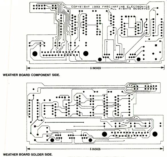
WEATHER BOARD COMPONENT SIDE
WEATHER BOARD SOLDER SIDE.
------------------
RAIN GAUGE
Complete kit-$29.90 (1) magnetic switch, 1.5x s/s-inch with hex nuts (Hamlin Mfg.) (1) disk magnet, '/c inch diameter (1) downspout adapter, 2x 3x 3inches, drilled (1) measuring spoon, Rubbermaid No. 2235 '/2 TBSP, drilled (1) plastic funnel, 8-inch diameter funnel (spout must be smaller than '/s-inch in diameter)
(1) 3-inch diameter schedule-40 PVC pipe, 3 inches long, drilled (1) brass rod, '12-inch diameter, 2.75 inches long (2) No. 6 stainless-steel sheet-metal screws, '/-inch long (2) cocktail straw sections, 3/4-inch long Hard-to-find parts kit-$5.90 (1) magnetic switch, 1.5x 5/+s-inch with hex nuts (Hamlin Mfg.) Assembled and tested rain gauge with 50-foot cable and modular plug--$59.90
--------------------
Barometer
Barometric pressure, caused by the atmosphere, constantly varies as high- and low-pressure systems circulate around the world. The first meteorologists used mercury barometers to measure barometric pressure. A mercury barometer has a column of mercury that rises and falls in accordance with the barometric pressure.
At sea level on a typical day, air pressure will support a column of mercury about 30 inches tall, abbreviated 30 in Hg. Pressure can increase to about 31 inches during fair weather, or decrease to 28 inches or lower during a storm. At higher elevations, normal pressures are lower; the normal barometric pressure at 5,000 feet above sea level is only about 25 in Hg.
The weather station measures air pressure with a Sen-sym SCC15A resistive-bridge pressure sensor (IC5). Op-amp IC2-d drives a constant current of 0.5.milliamperes through the bridge. Instrumentation amplifier IC3, an Analog Devices AD621, amplifies the very small signal from the SCC15A by a factor of 100. The AD621 requires plus and minus 10-volt power supplies.
Op-amp IC2-b, in conjunction with multiturn potentiometer R13. lets you compensate for pressure readings at your elevation. Op amp IC2-c amplifies the signal by 10, providing an output greater than 5 millivolts for each hundredth-of-an-inch of mercury.
The pressure sensor can be seen in Fig. 6.
The SCC15A pressure sensor is sensitive to light. To prevent changes in ambient light from affecting pressure measurements, put a small cover of opaque black plastic (or paper) over the sensor. The sensor is also sensitive to mechanical stress, so do not bend the sensor leads after the sensor has been calibrated.
Software
The standard software for the weather station is available on the Electronics Now BBS (516293-2283) as a self-un-archiving ZIP file called WEATHER.EXE. When you start the weather software you have the choice of beginning to take measurements, setting up the station, or exiting back to DOS. You can select functions by clicking on the function button with a mouse, or by holding down the Alt-key and pressing the highlighted letter in the button's name.
The setup menu lets you specify the instruments that are currently installed in your weather station. You can run the system with as few as one instrument and add new instruments at any time. The setup menu also lets you specify thecom port to which the Experimenter is connected. A setting is also available to simulate the Experimenter. Although this does not actually collect data, it's useful for demonstrating the software.
Selecting the calibration function connects the computer to the Experimenter and brings up the calibration menu.
-------------------
SENSORS
Temperature sensor kit-$15.90
(5) LM334Z current sources (National Semiconductor)
(5) 2.26-kilohm, 1% resistors
(5) 0.01 µF capacitors
(1) dual-wall heat-shrink tube, 3/16-inch diameter, 6 inches long
(1) DB-25M connector, with shell Humidity sensor kit-$29.90
(2) humidity sensors (Philips 2322 691 9001)
(2) 555 timer ICs (2) 0.1 µF disk capacitors
(4) 1 megohm, 1% resistors
(1) dual-wall heatshrink tube, 1/2-inch diameter, 3 inches long
Assembled and tested temperature and humidity sensors--$99.90
Includes: One humidity sensor and one temperature sensor on a 50-foot cable with a modular plug Four temperature sensors and one humidity sensor connected to a DB-25 connector with shell (includes one humidity sensor and one temperature sensor on a 10-foot cable, one temperature sensor on a 50-foot cable, and two temperature sensors on 30-foot cables)
Custom cable lengths are available, inquire for pricing.
--------------------
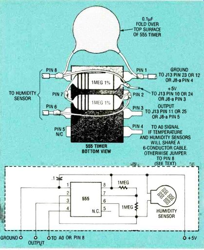
FIG. 5--WIRING A HUMIDITY SENSOR. Resistors are placed under the 555
timer IC as shown. A 0.01 µF capacitor is located on the top side of
the timer (see text).
The calibration menu displays the present readings from all of the instruments. This is very useful for debugging purposes. The function buttons in the calibration menu allow you to enter new calibration values for each of the sensors. Exiting from the calibration menu returns you to the setup menu.
When you select "begin," the computer starts to collect and display data. If your computer has a display capable of EGA graphics or better, a graphical display of all measured values appears; if not, a text display is shown. The professional version of software begins collecting data and storing it on your computer's hard disk.
Pressing the space bar causes the program to leave the graphic display and present a menu.
The professional version of the software provides you with selections for graphing stored data onscreen, or printing or plotting it. Data collection continues uninterrupted during these operations. You can also return to the calibration menu or DOS, but doing so will cause data collection to stop.
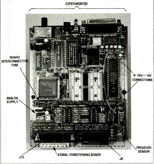
FIG. 6-THE WEATHER BOARD is mounted directly on the Experimenter as
a daughterboard. Note the pressure sensor is located on the weather
board.
Calibration
All that's left to complete the weather station is the calibration of the weather instruments. Let's start with the anemometer.
Anemometer. The anemometer's magnetic switch connects across pins 6 and 19 of the DB-25 connector J13. The signal-conditioning board also provides connections to pins 1 and 2 of modular jack J8-b if you prefer to use a separate connector for each of the wind instruments.
The R-C filter and pull-up resistor formed by R11 and C8 eliminates contact bounce that can occur when the magnetic switch opens and closes. The resulting filtered signal goes to TINO on the Experimenter. The Experimenter uses the wave-form's falling-edge to falling-edge time measurement function (Experimenter command C0 8) to measure the duration of a half rotation of the wind cups.
The weather station software has a default calibration factor, based on sample anemometers, that converts from the measured time duration to a wind speed. The accuracy of the default calibration factor is high, and no further calibration is usually necessary. However, if you determine a more accurate value for your particular anemometer, you can change the calibration factor in the calibration menu.
Wind vane. The electrical interface for the wind vane is very simple. Pins 1 and 4 of the wind vane's potentiometer connect from the analog supply to ground through pins 6 and 20 of J13. The two potentiometer wipers, pins 2 and 3, connect to pins 19 and 7 of J13. The wind vane can also be connected to pins 3-6 of modular jack J8-b.
The potentiometer gives the wind vane very good resolution of one degree with no "dead-band" in the readings due to the dual-wiper potentiometer. A wind vane offset value can be entered in the software's calibration menu. You can adjust this value to align the wind vane's direction readout with true North, rather than moving the mounting for alignment. If you find that the wind vane display rotates in the opposite way from the actual wind vane, just reverse the order of the four wires going to the potentiometer.
The wind instruments must be located away from obstructions that would block the wind.
Although mounting the instruments on top of an eighty-foot tall tree would be ideal, mounting on a five-foot pole in a field away from trees and buildings or on a three-foot pole strapped to a chimney should also be adequate.
CONDITIONING BOARD AND BAROMETER
Signal conditioning board and barometer kit-$49.90 (1) signal conditioning board (2) TLC2274 op-amps (National Semiconductor) or equivalent (1) 74HC393 dual counter (Harris Semiconductor) or equivalent (1) AD621 instrumentation amplifier (Analog Devices)
(1) SCC15A pressure sensor (Sensym)
(1) 20 kilohm multiturn potentiometer
(16) 0.1 µF disk capacitors
(2) 1-megohm, 5%, 1/4-watt resistors
(2) 10 kilohm, 5 %, 1/4-watt resistors
(5) 499-kilohm, 1 %, 1/4-watt resistors
(7) 100-kilohm, 1 %, 1/4-watt resistors
(1) 28.0-kilohm, 1 %, 1/4-watt resistor (1) 13.7-kilohm, 1 %, 1/4-watt resistor (1) 12.7-kilohm, 1 %, Y4-watt resistor (1) 10.0-kilohm, 1 %, 114-watt resistor (1) 2,87-kilohm, 1 %, 1/4-watt resistor (1) 1kilohm, 1 %, 1-watt resistor (1) DB-25M connector (3) triple 6contact modular jack Bare signal-conditioning PC board only-$19.90
Assembled and tested signal-conditioning board and barometer--$99.90
Includes:
Signal-conditioning circuitry for all the sensors Both DB-25 and modular connectors installed
Barometer that requires calibration at your location
SOFTWARE
Professional version software for PC--$39.90
Professional version software for MAC--$49.90
THE EXPERIMENTER
Experimenter kit-$149.90
Optional analog supply-$4.90
Assembled and tested Experimenter with analog option-$199.90 For more information on the Experimenter, see the July and August 1993 issues.
-------------
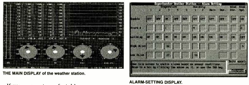
THE MAIN DISPLAY of the weather station. ALARM-SETTING DISPLAY.
If you are not comfortable working on your roof, you might call in a local contractor who installs and services TV antennas, as the mounting problems are very similar. Just be sure to test the wind instruments fully before installing them on the roof! Rain gauge. The electrical interface for the rain gauge is identical to that of the anemometer because both use the same type of magnetic switch.
The magnetic switch connects to pins 9 and 21 of J13. The signal-conditioning board also provides connections for the rain gauge at modular jack J8-c, pins 1 and 2.
The Experimenter counts pulses on the rain-gauge signal and converts the count into a rainfall reading. The software uses a default calibration factor based on measurement of typical units. To enter a new calibration factor based on your particular rain gauge, start the program and go to the calibration screen. Set the rain gauge in a 1-quart measuring cup under a slowly dribbling faucet.
The rain count should slowly increment. When the measuring cup is filled to the 1 quart mark, stop the water. This amount of water is equivalent to 2.3 inches of rain (based on an 8-inch funnel diameter). Divide the count number by 2.3, and the result is the number of counts your rain gauge produces for 1 inch of rain. Select the rain calibration from the software menu and enter the number you just calculated. Your rain gauge is now precisely calibrated.
Temperature sensor. A 32° Fahrenheit bath provides an ideal temperature reference.
Take crushed ice made from distilled water (or snow, if available) and put it in a cup with enough cold distilled water (or melted snow) to make a thick slush. Immerse the temperature sensors, secure in their protective tubing, in the slush.
Run the weather station software and select the calibration menu. Import the voltage readings from each sensor at this temperature for the 32 °F reference point by selecting the "import value" button on the screen.
To achieve the highest accuracy, perform a calibration at a second temperature point.
Put warm water (95 to 100 °F) in a thermally insulated container and immerse both the temperature sensors and an accurate thermometer. Enter the thermometer's reading in the temperature calibration menu, and import the voltages measured on each of the temperature sensors. Your temperature sensors will now be fully calibrated.
Humidity sensor. Verify that the sensor works by checking that the output for the sensor reads roughly 4000 microseconds in the calibration menu. If you exhale deeply on the sensor, the water vapor in your breath should make the reading increase.
To calibrate the humidity sensors, place them in a closed container with a wet cloth or sponge. Allow the container to sit overnight so that the interior air and humidity sensors can become completely saturated.
Go to the calibration screen in the weather station software, and select humidity and import the values from each sensor for 100% relative humidity. The humidity sensors will now be fully calibrated.
Barometer. Barometric pressure varies with respect to elevation. Multiturn potentiometer R13 is used for elevation compensation. To calibrate your sensor, you must determine the local air pressure. You can learn this by calling your local airport. Pilots refer to this pressure as the "altimeter setting." Once you have a value for your present local barometric pressure, start the program and go to the calibration menu. Find the nearest pressure and calibration value from Table 1 and adjust R13 to set the voltage reading to the value nearest the current pressure. You will not need to adjust R13 again, as all further barometer calibration will be done in software. Select the "baro" calibration button.
That will bring up a menu that allows you to specify the current pressure, and transfer the voltage reading corresponding to that pressure. This provides one calibration point.
To adjust for your pressure sensor's sensitivity the barometer must be calibrated at a second pressure. When the barometric pressure has changed significantly, you can provide the second calibration point.
Determine the current local pressure, enter the calibration menu and "baro" function, type in the current pressure for the second point, and import the current voltage reading. The barometer is now calibrated.
Also see: 100 Watt DUMMY LOAD