By Joseph J. Carr, CET
The voltage regulator is the circuit that keeps the output voltage of a do power supply steady under certain varying conditions. Voltage regulators are required because some electronic circuits won't operate at all, or will operate erratically, if the applied do voltage is not well regulated.
There are at least two sources of variation in the do power supply voltage. Perhaps the most obvious is the normal variation present in the ac line voltage. We normally specify the line voltage (in the USA) as 110Vac or 115Vac. In reality, however, the line voltage is rarely either of these figures and may vary markedly over the course of a normal day. The usual range is 105 Vac to 125 Vac, with some brownout conditions permitting as low as 95 Vac (fortunately, a rarity). The other source of output voltage variation is due to changing load current. An ideal do power supply has an internal resistance of 0 ohm (it is a perfect voltage source), but this ideal is never realized in practice: All do power supplies have internal resistance. Theoretically, we could compute this internal resistance by measuring the open-terminal (i.e. no load current) output voltage, and the short circuit load current.
Don't actually try to make this measurement, however, because the power supply may destroy itself when shorted out. The internal resistance is merely V /I.
We can illustrate the effect of internal resistance on output voltage using a circuit such as Figure 1.
Voltage source V in series with resistance R, the internal resistance, can be used to represent a practical supply. When the load RL is disconnected, a voltmeter connected across the terminals will read a certain value which we will call V. If switch S1 is closed, however, the power supply will deliver a current into load RL. Because current is now flowing, there will be a voltage drop across R, equal to the Ohm's law value IR,. This voltage must be subtracted from V, to find the voltage available for RL. In other words, V the output voltage when S1 is closed, will be V,-(IR,). We express the voltage regulation properties of the do power supply in the form of a percentage of regulation, which is computed using a scenario as in Figure 1 from the equation: REG(%) = (V-V,)/V Where: V is the open-terminal voltage, and V,, is the output voltage under load.
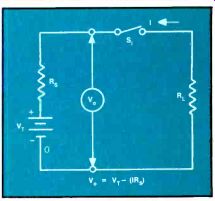
Figure 1. Internal source resistance causes variation of the output voltage
of a power supply.
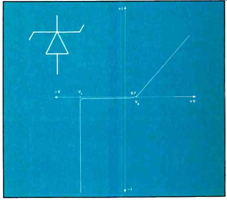
Figure 2. The zener diode (A) has a characteristic curve (B) with a steady
voltage over a wide range of currents in the third quadrant.
Zener diode voltage regulators
The zener diode is the simplest form of voltage regulator device available. Figure 2A shows the normal circuit symbol for the zener diode, while Fig. 2B shows the standard zener I-vs-V curve for such a device. Note in Figure 2B he that positive applied voltages cause the diode to operate just like any other PN junction diode. The current is limited to a small reverse leakage current from zero to the junction potential point (approximately 0.6V to 0.7V for silicon rectifiers), above which the forward current increases rapidly in an Ohm's law manner.
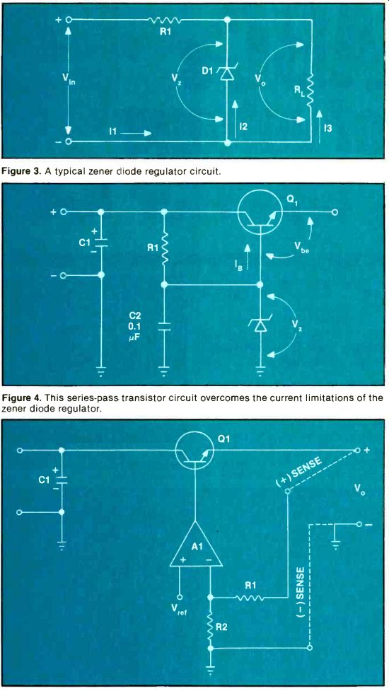
----------- Figure 3. A typical zener bode regulator circuit.
Figure 4. This series-pass transistor circuit overcomes the current limit zener diode regulator.
Figure 5. This circuit with its sense lines servos out IR drop in the power-supply lines.
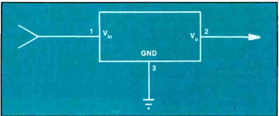
Figure 6. Voltage regulators are available in three-terminal IC packages,
such as this one.
The current is limited to leakage values in the reverse bias region, i.e. the region where the diode anode is negative with respect to its cathode. That is, until the reverse bias reaches a critical avalanche point, or zener voltage V,. At that point, the reverse current suddenly increases very sharply. Although there is some variation in the zener potential, it is for many practical purposes stable despite variations in-V. Thus, we can use the zener diode in this mode for voltage regulation.
A typical zener diode voltage regulator circuit is shown in Figure 3. Voltage V1 is the voltage across a filter capacitor in a do power supply; resistor RL represents the load; resistor R1l is a series resistor used to limit the current flowing in an avalanching diode; and Dl is the zener diode.
Note that output voltage V, is the same as zener voltage V,. We know from Kirchoff’s Current Law (KCL) that I1 = I2 + I3, where I3 is the load current drawn from the power supply and I2 is the zener current.
Limitations--The zener diode is not the ideal voltage regulator as some believe. It is limited in practical power supplies to low and moderate level operating currents.
For higher current levels, most designers use one of the other regulator circuits described in this article. These use the zener diode as a reference voltage source for a higher current pass element.
When precise voltages, or superior thermal stability, are needed, then use band gap zener diodes.
Series-pass voltage regulators
The current limitation of zener diodes can be overcome by using a series-pass transistor, such as Q1 in Figure 4. The high current is handled by the transistor, while the zener diode is used to set the potential at the base of the transistor. The nominal output voltage will be V,-Vbe. The maximum output current is approximately the product of base current I and the beta of transistor Q1.
Another series-pass circuit is the feedback regulator shown in Figure 5. In this circuit, a sample of the output voltage and a reference potential are applied to the differential inputs of a feedback amplifier (Al). When the difference between VA and V,4 is nonzero, the amplifier drives the base of transistor Q1 harder, thereby increasing the output voltage. The actual voltage will be stable at a point determined by The circuit in Figure 5 shows a feature that is highly useful in high current power supplies, especially where the supply must be operated more than a few inches from the load. The voltage divider R1/R2 takes the sample of output voltage V. that drives Al. The lines from the positive output and negative output to the voltage divider are separate from the main current-carrying lines. This allows us to place these sense lines at the points in the actual circuit where the value of V. must be maintained at a precise value. In a microcomputer using TTL devices, for example, we care little whether the voltage is + 5V at the output of the dc power supply, but care a lot that the voltage at the microcomputer printed circuit board is +5Vdc. If we connect (+) SENSE to the + 5Vdc bus, and () SENSE to the ground bus, then the feedback power supply will keep the voltage at the rated value at the PCB, not at the power supply! This method servos out IR drop in the power supply lines.
Three-terminal IC voltage regulators
Voltage regulators for low current levels (up to 5A) are reasonably simple to build now that simple 3-terminal IC regulators (Figure 6) are available.
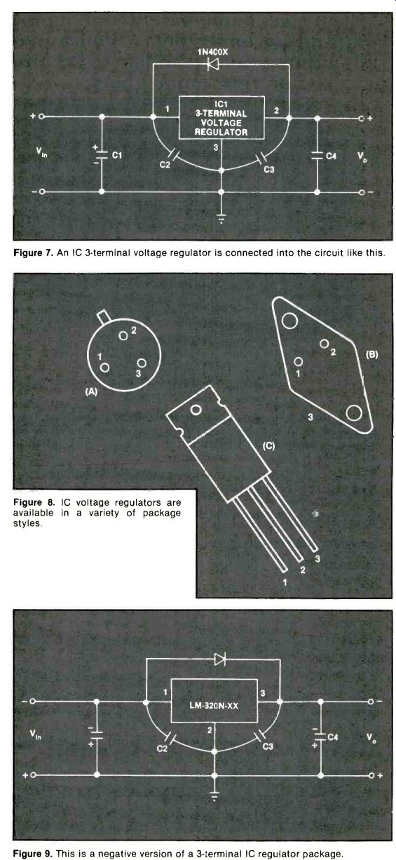
---- Figure 7. An IC 3-terminal voltage regulator is connected
into the circuit like this.
Figure 8. IC voltage regulators are available in a variety of package styles.
Figure 9. This is a negative version of a 3-terminal IC regulator package.
The circuit used with positive 3-terminal regulators is shown in Figure 7, while typical package styles are shown in Figure 8.
Capacitor C1 is the normal filter capacitor, and should have a value of at least 1,000µF per ampere of load current (some authorities insist on 2,000µF/ampere). Capacitor C4 is used to improve the transient response to sudden increases in current demand (something that happens in digital circuits). Capacitor C4 should have a value of approximately 100µF/ ampere load current. Capacitors C2 and C3 are used to improve the immunity of the regulator to transient noise impulses. These capacitors are usually 0.1µF to 1µF, and are to be mounted as close as possible to the body of the voltage regulator IC1.
In cases where there are frequent failures of 3-terminal voltage regulators you might consider three possible causes: a) too-high differential input-output voltage, b) high voltage input transients and c) circuit charge dumping back into the regulator circuit.
Let's consider the last of these first.
Diode D1 is not shown in a lot of circuits, but is highly recommended for applications where C4 is used, or there are other high circuit capacitances. If the diode is not present, then charge in C4 would be dumped back into the regulator when the circuit is turned off; that reverse current has been implicated in poor regulator reliability. The diode should be a 1A type at power supply currents up to 3A, and larger for higher current levels. For most 1A or less supplies, a 1N4002, 1N4003, 1N4004 or 1N4007 is sufficient (these diodes easily are found on the mail-order and TV-servicer markets). Adding the diode won't hurt the circuit, and may keep dreadful dogs from coming back.
Several 3-terminal IC voltage regulator packages are shown in Figure 8. The H package (Figure 8A) is used at currents up to 100mA, the K package (Figure 8B) at currents up to 1A (3A to 10A in some special cases) and the T package (Figure 8C) at currents to 750mA. These ratings are based in part on the internal power dissipation, which leads us to another failure mechanism. When the differential input-output voltage (V.-Vin) is very high, heat generation also is large. In these cases, poor reliability is often traced to insufficient heat sinking. Adding (or in creasing the size of) a heatsink could keep the set going long past the warranty date.
There are two general families of IC regulator. Some are designated 78xx, in which the xx is replaced with the fixed output voltage rating. Thus, a 7805 is a 5V regulator, while a 7812 is a 12V regulator. The LM-3.¢0y-xx series also is used. The y is the package style (H, K or T) while the xx is the voltage. Thus, an LM-340K-05 is a 1A, 5V regulator in a similar-to-T03 type-K package; an LM-3.40T-12 is a 12V, 750mA regulator in a plastic TO-220 power transistor package.
Negative versions of these regulators are available under the 79xx and LM-320y-xx designations.
Figure 9 shows the typical circuit.
Note that the diode is reversed, as are the polarized filter capacitors (C1 and C4). Note also that the pin-outs on the voltage regulator device are different from those of the positive regulator. There are zillions of blown negative regulators in the trashcans of people who failed to remember this little difference when wiring a negative regulator! The minimum input voltage to the 3-terminal IC voltage regulator is 2.5V higher than the rated output voltage. Thus, for a + 5V regulator, the minimum in put voltage is 7.5Vdc. The power dissipation is proportional to the voltage difference between this in put potential and the output potential. For a 1A regulator, therefore, the dissipation will be 2.5W if the minimum voltage is used, and considerably higher if a higher voltage is used. It is recommended that as close as possible to the minimum be used. For + 5V supplies used in digital equipment, a 6.3Vac filament transformer is sufficient.
When fullwave rectified and filtered with 1,000µF/ampere or more, the output voltage will be approximately + 8Vdc.
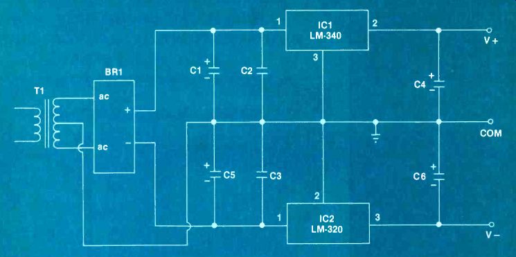
-- Figure 10. A dual-polarity dc power supply using one positive
and one negative IC voltage regulator.
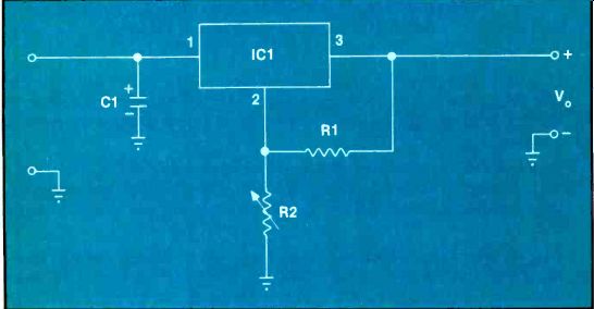
Figure 11. This is typical of a circuit using an LM-317 or 338 voltage regulator.
Figure 10 shows a dual-polarity do power supply such as might be used in operational-amplifier-based equipment, some microcomputers and other applications. The voltage regulator portion of the circuit is merely a combination of Figures 7 and 8. The transformer/ rectifier section bears some explanation, however. The rectifier is a 1A bridge stack, but is not used fullwave. The center-tap on the secondary of transformer T1 establishes a zero-reference, so the bridge consists of a pair of half-wave bridges connected to the same ac source. Thus, the (-) terminal of the bridge stack drives the negative voltage regulator, and the (+) terminal drives the positive voltage regulator.
Because Figure 10 is half-wave rectified, the 1,000µF/ampere rule is scrapped, and a 2,000µF/ampere preferred. Because this is a 1A supply, therefore, C1 and C5 are rated at 2,000µF. Also because of the halfwave rectification, the transformer rating must be greater than would be required for normal fullwave service. Because of the half-current rule, and the fact that the halfwave rectifier is less efficient than the fullwave, it is recommended that the secondary of T1 deliver at least 2.8 times the amount of current available from both V- and V+ . Adjustable IC voltage regulators The LM-317 and LM-338 voltage regulators are capable of delivering up to 1.5A and 5A, respectively, at voltages up to + 32Vdc.
Figure 11 shows a typical circuit for these regulators. In some cases, fixed resistors provide a fixed output voltage, while in others a potentiometer is used to provide adjustable voltage. The input voltage must be 3V higher than the maximum output voltage.
The output voltage is set by the ratio of two resistors, R1 and R2, according to the equation: V,, = (1.25V) ((R2/R1) + 1)
An example from the National Semiconductor, Incorporated Linear Databook shows 120 ohm for R1, and a 5k ohm potentiometer for R2. This combination produces a variable output voltage of 1.2Vdc to 25Vdc, when V;,, is >28Vdc.
Diode D1 can be any of the series 1N4002 through 1N4007 for LM-317 supplies, and any 3A type for LM-338 supplies.
Troubleshooting In general, troubleshooting the IC 3-terminal regulator is simple: measure the pin voltages. A bad regulator generally produces a voltage that is either too high or too low. If the other pin voltages are near normal, then it's a reasonably sure bet that the IC regulator is bad. Although faults such as low input voltage, an open ground line on the printed circuit board, or a short in the output circuit can counterfeit a bad regulator problem, these are easily checked out.
Reliability problems
Earlier I mentioned three main causes of reliability problems. Two of these have been discussed. The last, destruction of the device by high voltage transients, can be found most often in equipment operated from poor ac power lines, or in close proximity to machinery that places transients on the line.
A lot of industrial electronics equipments fail for this reason.
The voltage regulator may be protected by: A.) ensuring that 0.1µF to 1.0µF capacitors shunt the input and output terminals of the IC voltage regulator; and, B.) a metal oxide varistor (MOV) device shunts the ac power lines that feed the power supply.
Parts substitution
There are remarkably few 3-terminal fixed and adjustable voltage regulators on the market.
I recommend technicians keep at least the National data book on hand for purposes of locating and identifying suitable substitutes when parts for equipment being serviced are either too hard to obtain or are too costly. Any number of sources, both industrial and mail order, offer lower prices on generic 3-terminal regulators than some of the regular sources that a servicing technician might rely on.
Renovating older equipment
During the time when I serviced biomedical electronics equipment in a large eastern hospital, there were many times when older equipment arrived in our shop with a burned up do voltage regulator circuit. In most of these equipments, the voltage regulator was on a separate plug-in printed circuit board. Those circuits were made from discrete transistors, and output ± 12Vdc at less than 1A. We often made new circuit boards (the older ones being unavailable) from Vector perfboard (the kind with a card-edge connector on one end). The circuitry was merely K-packaged LM-series 3-terminal IC regulators: LM-340K-12 for + 12Vdc and LM-320K-12 for-12Vdc.
Conclusion
All sorts of electronic equipment, consumer, industrial, commercial and military are being designed with 3-terminal IC voltage regulators. There are only a few generic types on the market, and you can substitute these generics for the part numbered versions of the same devices in equipment that you service.
Also see: Link | --Why do components fail?