In this installment of Op Amps we will give you some very practical background in active filters and try to take the mystery out of their basic design and operation.
By Bernard B. Daien
In the last few years, op amps have been developed for use with a single power supply. In the main, they are in tended for ac inputs (audio). Many of these devices are "Current Differencing Amplifiers" (CDAs), sometimes referred to a "Norton Amplifiers," or "current mirror amplifiers." These op amps are quite different in use, and deserve a little discussion . . .
Current differencing amplifiers
CDAs are designed to operate with an input voltage swing that can go down to zero, or up to full power supply voltage. The output swing goes to within a quarter volt of ground, and up to within one volt of the supply voltage. A good example of this op amp is the LM3900, a quad op amp (four in a package), which works well in audio circuits, is very inexpensive, and commonly available.
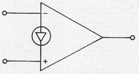
Fig. 1. The current differencing amplifier. Symbol used for CDA (current differencing
amplifier). This amplifier operates with a current input, and the inputs look
like a forward biased diode to the signal source.
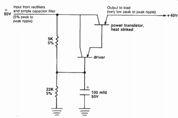
Fig. 2. An electronic ripple filter. The base of the driver is tied to a voltage
divider which provides close to 42 volts base voltage This voltage is easily
filtered (because of the low current involved) by the 100 mfd capacitor The
driver functions as an emitter follower, driving the power transistor (another
emitter follower) The output of the power transistor is close to + 40V. but
with very low ripple, since its base drive comes from a filtered source The
output dc will stay at 80 % of the dc input, as the dc input changes, hence
is not regulated it is filtered as if by a series iron cored inductor and a
very large shunt capacitor (an LC filter).
The manufacturers of CDAs have been trying to establish a new op amp symbol, to differentiate between conventional op amps and CDAs. The symbol is shown in Figure 1. There is a very good reason for emphasizing on a schematic that a CDA is being used … the input of a CDA is a current, while in most op amps the input is a voltage. In fact, the input of a CDA looks much like a forward biased diode, or an emitter base junction of a bipolar transistor (which it is). Now you already know that if you attempt to drive the emitter base junction of a transistor with an input greater than 0.6 volts, the diode (junction) simply conducts, and clamps the voltage to 0.6 volts. Any attempt to increase the input voltage simply results in a larger input current. Stated another way, a forward biased silicon junction is a good 0.6 volt voltage regulator, functioning much like a zener (except of course, that it is forward biased). The CDA input therefore behaves in a similar manner. As a result, if you wish to drive a CDA from a voltage source, YOU MUST use a series resistor between the source and the CDA input.
Normally, with a conventional op amp, using the inverting input, we do the same thing BECAUSE THE INVERTing INPUT IS A VERY LOW IMPEDANCE due to the feedback being applied to it. However, the NON INVERTING INPUT IS NORMALLY A VERY HIGH IMPEDANCE, which is NOT the case with the CDA. Thus the CDA requires a series input resistor for both the inverting, and the non-inverting inputs.
Of course, if you are driving the CDA with a current source, a high impedance generator ... as discussed earlier i this series, then the resistor may be omitted. (A high impedance source limits the current due to the internal impedance of the generator itself). Since much of our electronic equipment operates with a single power sup ply, CDAs are attractive for such uses as active filters. Generally these applications use more than one op amp, and the dual and quad op amps are very small and inexpensive, and thus particularly attractive for such circuitry. CDAs are made in multi op amp packages, as previously mentioned; thus the use of CDAs is growing for these applications.
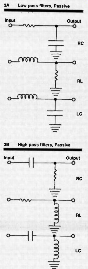
Fig. 3. Passive filters Note: Active filters use only RC and op amps to duplicate
these basic filters, and others. 3A Low pass filters, Passive 3B High pass
filters. Passive
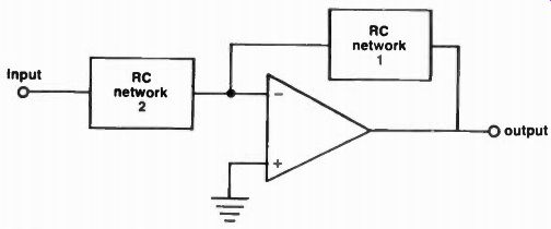
Fig. 4. A basic active filter with a single feedback path Note: This is a
“single feedback path" circuit because only one RC network is in the feedback
loop (The other is simply in series with the input.) This filter has two RC
networks, each providing 6 db per octave roll off (a change of 2X in amplitude
for a 2X change in frequency). Both RC networks together provide 12 db per
octave roll off, or a 4X change in amplitude for a 2X change in frequency (Twelve
db per octave is also 40 db per decade, or a 100X change in amplitude for a
10X change in frequency) Additional RC networks can be added to provide faster
roll offs, since the op amp provides gain to offset the losses.
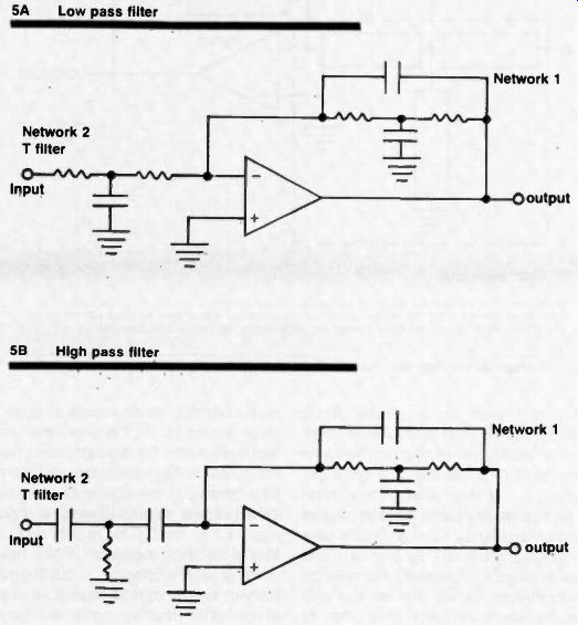
Fig. 5. Single feedback active filters 5A Low pass filter 5B High pass filter
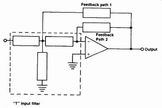
Fig. 7. A basic active filter with multiple feedback paths Note: Each
block represents a resistor or a capacitor. The input filter is a "T" as
in the single feedback active filters. There are now two feedback paths from
the output to the input. Each feedback path connects to a different point on
the T input filter Fewer parts are needed in the multiple path active filters.
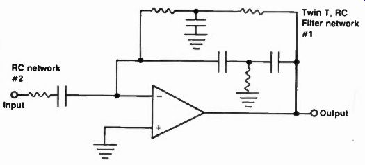
Fig. 6. A single feedback, bandpass, active filter.
Active filters
The active filter generally eliminates the need for inductors . . . and audio inductors are large, heavy, and expensive. (Mounting them on a printed circuit board is a problem in itself). Active filters can be readily made to cover frequencies down to a fraction of a cycle per second . . . or even lower. They come in high pass, low pass, band pass, and notch filters. They have as much gain as desired, are small, light, cheap, and easily "tuned" or "aligned." Active filters come in such variety that we can only discuss some of them here, due to space limitations . . but the examples given will enable the reader to better understand the basic active filters, and hopefully, pursue the subject further, with enough understanding of the topic to facilitate self study.
Active filters are used increasingly in power supplies, to reduce ripple. You must be careful to differentiate between an electronic "filter" and a "voltage regulator" however. It is true that a voltage regulator also reduces ripple ("filters"), but it does this by holding the output dc level constant, which results in quite a bit of dissipation as the powerline voltage rises, since the regulator must hold the output voltage constant, and there fore "absorbs- the difference between the input and output voltages, and dissipates it as heat. (This is only partially true of switching regulators, which have much greater efficiency . . . but the majority of simple voltage regulators used in consumer electronic equipment today are still the straight "Series type transistor regulator," or, even worse, a brute force "shunt type" zener regulator). An electronic filter is shown in Figure 2, along with the explanation of its operation. Notice that if the input dc voltage rises, the output voltage will also rise. In the case shown, the output voltage will always be close to 80% of the input voltage, but with a much lower voltage. Due to the gain of the transistors, which are active devices, the circuit behaves like a passive filter with very large filter elements. Thus relatively small capacitors are made to appear as large capacitors and inductors, saving weight, size, cost, and power. The use of such electronic filters contributes materially to the light weight of modern portable High Fidelity, and Television receivers.
Active filters also have several other desirable features . . . some of them not so obvious. For example . . . active filters can be designed to have very high input impedance, reducing loading on high impedance sources. They can also be designed to have very low output impedance, thus being able to drive a wide variety of loads. Active filters also can provide a very high degree of isolation, or buffering. And, of course, they provide voltage, current, or power gain.
On the other hand, active filters also have a few disadvantages. An active filter cannot be free of connections to the supply, and to ground, as, for example, a parallel tuned "absorption trap" which is free of all connections to anything else. They also cannot be used at high power levels, or high voltage levels, as in transmitter use. Finally, and perhaps most significant, when an active filter is used for ripple suppression, as in a power supply, it does not have energy storage capability. Thus the filter is unable to hold the output voltage up during momentary drops of outages in the supply. This can be very important in certain applications.
Most discussions of active filters are concerned with the theoretical considerations, and replete with mathematical formulae. As a result it is very difficult to build an active filter for practical use.
This discussion will be in two general areas ... the theory, and ... some practical filters you can easily modify for the particular frequencies you want to use. It turns out that the active filters with the most THEORETICAL advantages are not easily adapted to use with simple computations and adjustments . . . while the filters which seem to offer fewer advantages, are easier to calculate, adjust, and use, and therefore are most practical. After our discussion concerning HOW active filters work, there will be a collection of practical circuits you can easily build, adjust and use.
Ho w they work A variety of R C, and R L passive filters are shown in Figure 3, and they are certainly familiar to the average technician.
Active filters simply do the same job, but use R C networks to replace the coils.
And when we replace LC networks, again we use only R and C components to the job.
This is possible because the active filter has the ability to PHASE INVERT signals. If you think about it, an inductor causes a phase lag in current of 90°, while the capacitor causes a current lead of 90°. Thus the capacitor is 180° out of phase with the inductor. If we use a capacitor to cause a 90° leading current, then phase invert the current, the result will be a lagging 90° current ... or an inductive current! Thus a simple bipolar transistor in a common emitter circuit, along with a capacitor and a few resistors, can behave like an inductor ... since the transistor is a phase inverter. More about this later.
Using the gain of an amplifier, with inverting and non inverting inputs, we can also create simple feedback loops from output back to input. We can use negative feedback to reduce gain ... and if the negative feedback loop contains a capacitor in it, we can reduce the gain on a frequency selective basis.
Using positive feedback, on the other hand, we increase gain ... and if we use a capacitor in the positive feedback loop we can increase gain on a frequency selective basis. Thus we can use feedback loops to create frequency selective networks, and the result will appear at the output of an op-amp.
Further, we can put a simple A/C net work in series with the input to the op amp, thus we have three frequency determining networks. Finally, it is possible to put another R/C network in the output of the active filter, thus obtaining a total of four frequency selective net works, which can work so as to add together in cumulative effect forming high pass or low pass filters . . . or combine in such a way as to form band pass and band stop filters.
It is possible that we could use passive RIG networks to do some of the same things ... but passive networks all have losses, and combining several of them results in a very small signal ... in the noise." This happens be cause passive networks obtain their roll offs by reducing gain only, whereas an active filter can start at some gain, level, and, after roll off, still yield a useable signal level. Further, passive filters need some sort of isolation, or buffering, to prevent undesirable reactions between them . . . and the op amp in the active filter provides this action.
The basic, most commonly discussed active filter is shown in block diagram in Figure 4. One RC network is used in the feedback loop between the output and the INVERTING input (negative feedback, frequency selective), and the other RC network is inserted between the signal source and the input to the amplifier. Figure 5 shows how this circuit can be implemented for high pass, and low pass functions, by merely reversing the positions of some of the R's and C's. This circuit is known as the "single feedback active filter" because it has one RC filter in the feedback to THE INVERTING INPUT, (and one RC filter in the input, but not in the feedback loop). This provides a roll-off of 12 db per octave (the gain is changed 4X for each 2X change in frequency). Or, stated another way, the roll off is 40 db per decade (100X change in amplitude for a 10X change in frequency). Both the high pass and low pass single feedback active filters used a complex RC filter in the feedback loop, and the reader is urged to review both "bridged T" and "Twin T" RC filters, since they have common application in active filters, and their review here would take more space than would be practical in this series.
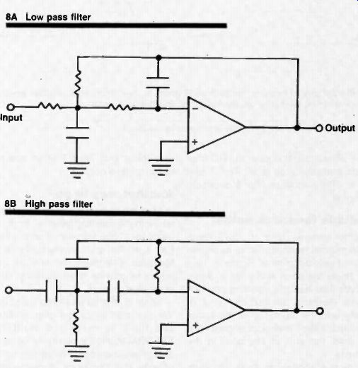
Fig. 8. Multiple feedback active filters.
Note that positions of A and c are reversed for high pass and low pass versions.
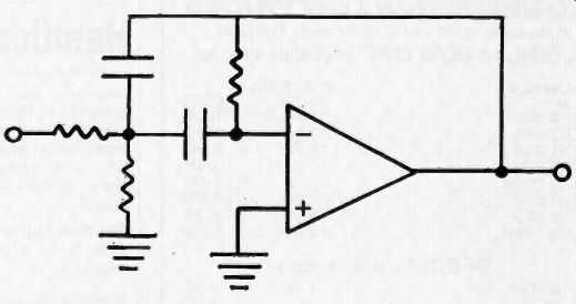
Fig. 9. A multiple feedback bandpass active filter.
It is also useful to use the single feed back active filter to form a bandpass filter, although in this case the RC filter in the feedback loop is a "Twin T net work." The bandpass filter is shown in Figure 6.
Multiple feedback paths
Another general class of active filters uses multiple feedback paths, as shown in the block diagram of Figure 7. Like the single feedback active filters, these circuits also use the inverting configuration, therefore the output is out of phase with the input. Unlike the single feedback filters, fewer components are required, but gain is sacrificed in the process.
Figure 8 shows low pass and high pass multiple feedback active filters, while Figure 9 shows the bandpass version. Note that Twin T filters are not used in these circuits.
Another way to go In all of the above circuits, the feedback was into the inverting input . . . negative feedback. Thus we started with a high gain amplifier, and by means of inverse feedback, selectively reduced the gain so as to provide the frequency characteristics desired.
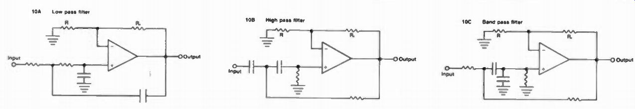
Fig. 10. Active lifters using positive and negative feedback.
Note the use, of negative feedback via R, and R to inverting input to establish low closed loop gain. Positive feedback to non-inverting input then causes frequency selective gain increase.
There is another way to go about this.
We can start with a low gain amplifier, and then, by means of POSITIVE FEEDBACK into the non inverting input, selectively increase the gain so as to provide the frequency characteristics desired. Naturally you can spot this type of amplifier because it has the feedback loop with the RC networks, connected back to the non-inverting input terminal.
Figure 10 shows the high pass, low pass and band pass filters using this type of circuit. Notice that the inverting input is fed from a simple voltage divider, which has a flat frequency response, thus fixing the gain of the amplifier at some relatively low level (compared to the amplifier's open loop gain). The feedback into the non-inverting input (positive feedback), has RC frequency shaping networks included, and thus establishes the active filter response curve, by increasing the op amp circuit gain over the level set by the negative feedback. Since it is necessary to first set the op amp gain by means of the negative feedback, in this type of active filter, it is called a "controlled source" active filter.
Still more .. .
There are other types of active filters, and we will discuss them in the last part of this series ... in order to cover a basic introduction to the scope and variety of active filters. Some practical active filters will be shown, along with in formation useful for modifying them for the reader's specific needs. We will be covering low pass, high pass, band pass, and notch filters. Also to come are trouble-shooting tips for op amps and suggestions as to where to obtain further information.
(source: Electronic Technician/Dealer)
Also see: Operational Amplifiers, Part 1
Opamps, part V -- Practical active filters and troubleshooting