(source: Electronics World, Apr. 1968)

By PAUL MUCHNICK / Manager, Advanced Product Development Dept., Sorensen
Operation, Raytheon Co.
The author received both his B.E.E. and M.E.E. degrees from New YorkUniversity where he also engaged in research and teaching in the areas of control-system design and high-speed camera shutters. For the past seventeen years, he has been with Sorensen, working in power-supply design, development. He is former chairman of the Standards Committee of the NEMA Electronic Power Supply Group. He holds five patents in the power supply field, has been a contributor to several engineering handbooks, and authored numerous published and unpublished reports and articles.
He is a member of the IEEE, Tau Beta Pi, and Eta Kappa Nu.
Characteristics of various types of regulators for a.c. power lines, including ferroresonant, saturable reactor, SCR, electromechanical, and fast-response.
A.C. SIGNAL, may be defined in terms of amplitude, frequency. and phase. An a.c. regulated power supply usually regulates only the amplitude parameter of the incoming a.c. line. If the power supply also regulates the frequency, then it must almost certainly mean that the input and output voltages are non-synchronous. Such devices are commonly referred to as frequency-stabilized power supplies.
The a.c. regulated power supplies may be divided into two main categories, depending on whether or not the input and output frequencies are synchronous. Synchronous frequency units are called a.c. line voltage regulators, a.c. voltage stabilizers, or a.c. line conditioners. These devices regulate the input line for peak, average. or r.m.s. amplitude, while retaining the frequency characteristics-but probably introduce a phase shift.
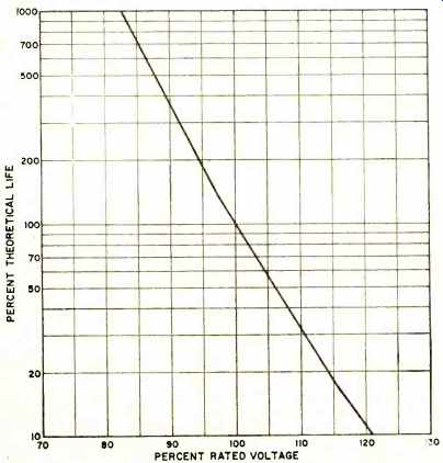
Fig. 1. With just a 10% over-voltage applied to incandescent lamps, life
expectancy is only about 30% of the rated value.
The non-synchronous types are called inverters when the device operates from a d.c. source or frequency changers when the input is a.c. There are specialized types of frequency changers whose inputs and outputs are harmonically related: these sometimes carry the more descriptive terms frequency doublers, triplers, etc. This group of power supplies may be either self-excited or driven by a low-power oscillator.
The National Electrical Manufacturers Association (NEMA) recommends that commercial a.c. supply voltage should be maintained to ±10% constancy. Yet there are a great many applications where such variations are too great to provide either reliable performance or consistent and reproducible data. In addition, momentary and intermittent heavy loads cause even wider voltage variations that result in erratic performance and equipment malfunction. Even relatively small over-voltages will seriously reduce the life of incandescent lamps or ninny other devices that are connected to the a.c. line (Fig. 1) . To reduce or eliminate these problems, a.c. line regulators are installed in equipment, power benches or groups of benches, individual assembly lines, and entire plants.
It is therefore not surprising that this type of regulator occupies a position of prime importance in the power supply market.
The size of the a.c. line regulator market is as difficult to estimate as is the d.c. regulator market which has received considerably more attention. Bearing in mind that such estimates may vary by as much as 10 to 1, it is believed that the market for the electronically controlled static (non-mechanical) types is in excess of $7 million per year with a relatively shallow growth of less than 10% a year. The market for ferroresonant a.c. regulators is possibly half this size.
The Variety of Designs
These a.c. line regulators are made in a great variety of electrical and mechanical designs for an extremely broad range of applications. The various designs include:
1. ferroresonant regulator, 2. electronically controlled saturable-core reactor regulator, 3. silicon controlled rectifier regulator, 4. electronically controlled electromechanical regulator, and 5. the amplifier or fast-response regulator.
These types are available in capacities that range from as low as 15 VA in ferroresonant types to several hundred kVA for electromechanical types. Still larger capacities are available in induction and tap-changing types. The output voltage settings of regulators may be fixed, or adjustable over either narrow or wide limits. The acceptable range of input frequency is generally relatively narrow with degeneration of setting, regulation, and harmonic distortion occurring around a nominal value. Percent regulation can vary over the extremely wide range of better than 0.01% for line and load to almost 10% for load.
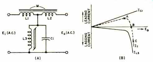
Fig. 2. (A) Equivalent circuit of constant-voltage transformer or ferroresonant
regulator. (B) Current-voltage characteristics of the shunt components
C1 and L3 used.
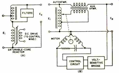
Fig. 3. (A) Autotransformer-reactor regulator. (B) Electromechanical
regulator uses motor-driven autotransformer.
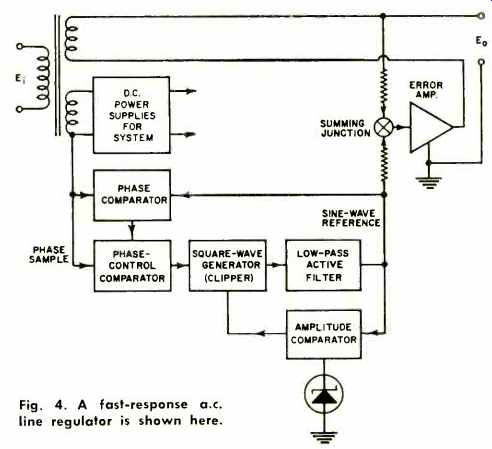
Fig. 4. A fast-response a.c. line regulator is shown here.
Speed of response varies from microseconds to a full second response. Output distortion is another important parameter. Some units introduce considerable amounts of distortion such as peak clipping or other nonlinearities resulting from the use of saturable-core inductors, while others operate on the incoming waveform to actually filter out harmonics.
1. Ferroresonant Regulator: The constant-voltage transformer or ferroresonant regulator is a relatively simple open-loop regulator depending solely upon saturation of iron-core material for regulating action. They are extremely economical and reliable, and are self-protecting for overloads in that shortcircuit current is limited to about 200% of rating. They have no moving parts or external adjustments.
While this type of regulator is excellent for fixed loads that do not require extremely rapid response (e.g., filament power) , it has some disadvantages. The saturation of some of its components results in considerable distortion of the output-voltage waveform (unless special low distortion types are used Editor) , load regulation is generally poor, and output voltage setting is heavily dependent on input frequency.
The equivalent circuit for the regulator is shown in Fig. 22A. L1 and D2 are linear chokes while L3 is self saturating. The L3-C1 combination has a current-voltage relationship as shown in Fig. 12B. Over the region A-B (on the curve of total shunt current) this network draws a capacitive current that produces a drop across L1 of such a polarity as to make E. greater than E;. Over the region B-C the current drawn is inductive, resulting in E. being smaller than E;. This correction is by no means perfect, so a compensation winding L2 coupled to L1 is added to the circuit to improve its operation.
The output voltage level of this regulator may be varied by several means. These include: variation of L3-C1 product; variation of turns or the amount of iron used in L3; and variation of core material of L3. A variation in the impedance of the linear chokes will shift the input operating range.
Special ferroresonant designs with low harmonic distortion are available, but other characteristics may suffer.
2. Electronically Controlled Saturable-Core Reactor Type: The circuit in Fig. 3A is typical of the basic design of this closed-loop regulator. Regulated output is obtained by controlling the d.c. current through the control winding of the saturable-core reactor, thereby varying its inductance. The result is that corrective voltages are produced at the autotransformer which add or subtract vectorially from the input voltage. The entire closed-loop system consists of an r.m.s. voltage detector on the output, comparison to a reference, generation of an error signal, and amplification to generate reactor drive power.
Since the circuit is non-linear in operation, distortion is generated in the system. This is reduced by the addition of harmonic filters across the autotransformer. Only odd harmonic filters are required.
This regulator has a response time of 0.02 to 0.15 second. Its output setting is only slightly affected by frequency, and line and load regulation can be 1 or 2 orders of magnitude better than the ferroresonant type. The output is easily adjustable. Disadvantages include, in addition to the 3% or 4% of generated harmonic distortion, an appreciable phase shift that varies with line and load setting.
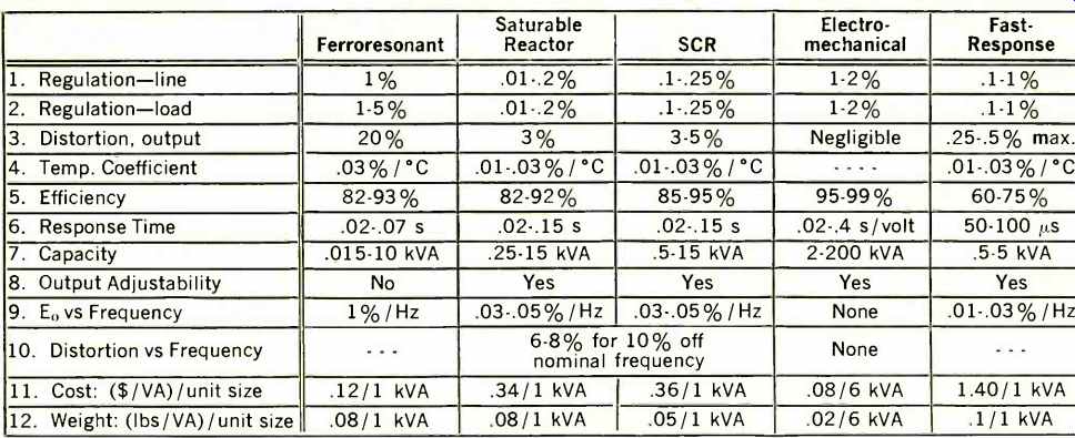
Table 1. Summary of the most important characteristics of the a.c. line
regulators described here.
3. Silicon Controlled Rectifier Regulator: These regulators are all-solid-state versions of the saturable-core reactor type just described. The major difference is the substitution of SCR's for reactors. Inasmuch as the SCR is not as rugged as the reactor for overloads, this regulator usually has an over-current protection system included in the form of special protective circuitry and /or fuses. The temperature-limited vacuum-diode r.m.s. detector used in saturable-reactor systems is replaced by a solid-state detector which may not perform as well, so performance may suffer in some areas (e.g., E. vs frequency). In the larger sizes, these units are less expensive, more reliable, and smaller than the previous design.
4. Electronically Controlled Electromechanical Regulator: The simple design philosophy of this buck-boost system yields a regulator that produces almost negligible distortion and phase shift, insensitivity to frequency, and very high efficiency. The disadvantages are slow response and recovery time, rather poor regulation of 1% to 2%, and some maintenance required due to moving parts and contacts. Economic advantages over the SCR type units appear only above 5 to 10 kVA levels. The unit consists of a voltage-.sensitive bridge, a control circuit. and a motor-driven variable autotransformer (Fig. 3B). The system is quite easily adapted to three-phase regulation by mounting three autotransformers on a common shaft.
5. Fast-Response Regulator: These units use vacuum tube or solid-state amplifiers to add to or subtract power from the incoming a.c. line. They have very fast reaction time. approaching 50 us, hence the ability to not only regulate r.m.s. levels but reduce incoming harmonics by acting as a filter.
A typical block diagram of such a regulator is shown in Fig. 4. A sample of the input voltage first has its phase compared to the sine-wave reference and corrected to an 180° out-of-phase condition. It is then squared and clipped to develop a symmetrical square wave. The amplitude is kept constant. Filtering then follows to produce a stable, pure AC sine-wave reference signal. This reference and the output are compared and the error is amplified to correct the output level. Regulators of this type are most advantageous where incoming transients or distortion is great enough to affect measurements adversely.
A summary of the characteristics of the various a.c. line regulator: is given in Table 1.
Non-synchronous poker supplies generate their output by first rectifying the input power and then applying the resultant d.c. to some type of power oscillator and /or amplifier. These systems are discussed in other articles in this Special Section. Regulation schemes include high gain feedback amplifiers: r.m.s. detection of the output to control the d.c. voltage level feeding the inverter: and controlled variable loads, such as SCR's, on the output of the power supply.
The generation of three-phase regulated voltage is a particularly interesting problem. Because of the variable mature of phase shift through the inverters (due to changes in line and load) . two voltages are usually generated and regulated. A third circuit regulates the phase angle between them. The third output voltage is generated by adding these two voltages and shifting the resultant by 180 degrees.
POWER SUPPLY MODULES
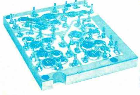
Fig. 1. Hybrid assembly of a stepping motor-drive power supply. The three
light sections are an aluminum-oxide coating over a metallic substrate.
Copper is flame-sprayed on the oxide to form a mounting surface for the
active elements. Radiators are not used.
HI-PAC (high-density packaging), developed by Solitron Devices, is a method of coating metallic substrates with aluminum-oxide to provide a low thermal resistance path. Copper is flame-sprayed on the aluminum-oxide surface to form a base for electrical interconnections. The result is a system with a high built-in heat-sinking potential. In addition, the process greatly facilitates multilayering, through-hole connections, and around the corner circuitry.
The copper surface is ideal for mounting chip components because it eliminates the need for stud bases and transistor cans as heat dissipators. The thermal resistance of the mounting board, from chip to substrate, is less than 0.7° centigrade per watt and the dielectric insulation is rated at 500 volts per mil.
As an example of what is attainable with the Hi-Pac process, a power hybrid assembly for a stepping motor-drive power module is shown in Fig. 1. Each of the three sections contains a Darlington pair (5-ampere transistor driving a 20-ampere device) and another 5ampere unit to supply motor field current. Each section is step operated at a peak current of 17 amps and an average current of 8 amps, at 80 volts d.c. Each section also dissipates 48 watts (120 watts peak). The assembly, less components, is about 3 1/2 x 3 1/2 x 3/8 inches-a very small package for the high power rating of the module.
Most Hi-Pac power modules have been developed for special customer applications. In the near future, however, Solitron expects to develop a standard line of hybrid power modules.