The 6BN6 Gated-Beam Tube. Another approach to a combined limiter-discriminator combination, one that differs considerably from any of the previous circuits, is provided by the 6BN6 gated-beam tube. This tube, designed by Dr. Robert Adler of the Zenith Radio Corporation, possesses a characteristic such that, when the grid voltage changes from negative to positive values, the plate current rises rapidly from zero to a sharply de fined maximum level. This same maximum value of plate current remains, no matter how positive the grid voltage is made. Current cut-off is achieved when the grid voltage goes about 2 volts negative.
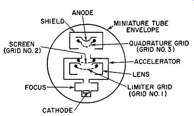
Fig. 9.28. The internal construction of the beam-gated tube.
The reason for this particular behavior of the tube stems from its construction. (See Fig. 9.28.) The focus-electrode, together with the first accelerator slot, forms an electron gun which projects a thin-sheet electron stream upon grid 1. The curved screen grid, together with the grounded lens slot and aided by the slight curvature of grid 1, refocuses the beam and projects it through the second accelerator slot upon the second control grid.
This grid and the anode which follows are enclosed in a shield box. Internally, the focus, lens, and shield electrodes are connected to the cathode.
The accelerator and the screen grid receive the same positive voltage be cause both are connected internally.
The foregoing design is such that the electrons approaching the first grid do so head-on. Hence, when grid 1 is at zero potential or slightly positive, all approaching electrons pass through the grid. Making the grid more positive, therefore, cannot increase the plate current further. When, however, grid 1 is made negative, those electrons that are stopped and repelled back toward the cathode do so along the same path followed in their approach to the grid. Because of the narrowness of the electron beam and its path of travel, electrons repelled by the grid form a sufficiently large space charge directly in the path of other approaching electrons, thus causing an immediate cessation of current flow throughout the tube. In conventionally constructed tubes, the spread of the electron beam traveling from cathode to grid is so wide that those electrons repelled by the grid return to the cathode without exerting much influence on other electrons which might possess greater energy and therefore be able to overcome the negative grid voltage.
It is only when the control grid voltage is made so negative that no emitted electrons possess sufficient energy to overcome it that current through the tube ceases. These differences between tubes may be compared to the difference between the flow of traffic along narrow and along wide roads. Along the narrow road, failure of one car to move ahead can slow down traffic considerably; along the wide road, more room is available and the break down of one car has less effect.
The electron beam leaving the second slot of the accelerator approaches grid 3 also in the form of a thin sheet. Thus, this section of the tube may also serve as a gated-beam system. If this second grid is made strongly negative, the plate current of the tube is cut off no matter how positive grid 1 may be. Over a narrow range of potentials in the vicinity of zero, the third grid can control the maximum amount of current flowing through the tube. However, if the third grid is made strongly positive, it also loses control over the plate current, which can never rise beyond a predetermined maximum level.
So much for the operating characteristics of the tube. Now let us sec how it can be made to function as a limiter-discriminator. A typical circuit is shown in Fig. 9.29.
It has been noted that when FM signals reach the discriminator they contain amplitude variations. When the 6BN6 gated-beam tube is used, these signals are applied to control grid 1. If the signal has received sufficient prior amplification, it will have a peak-to-peak value of several volts.
Upon application to grid 1, current through the tube will start to flow only during the positive part of the cycle and will remain essentially constant no matter how positive the signal may become or what amplitude variations it may contain. Thus, signal limiting is achieved in this section of the tube, the electron beam being passed during the positive half-periods of the applied signal and cut-off occurring during negative half-periods. The groups of electrons that are passed then travel through the second accelerator slot and form a periodically varying space charge in front of grid 3. By electro static induction, currents are made to flow in the grid wires. A resonant circuit is connected between this grid and ground, and a corresponding voltage of approximately 5 volts is developed at grid 3. The phase of this voltage is such that it will lag the input voltage on grid 1 by 90°, assuming that the resonant circuit is tuned to the intermediate frequency. (Because of this 90° difference between grid voltages, grid 3 is often referred to as the quadrature grid.)
The idea of electrostatic induction, while it has not been labeled as such, was encountered in the previous discussion of the 6A8 pentagrid converter.
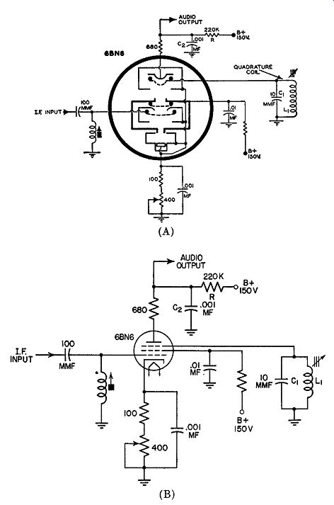
Fig. 9.29. The beam-gated tube connected as a limiter-discriminator.
(A) Tube shown in pictorial form. (B) Tube drawn schematically.
Whenever a group of electrons approach an element in a tube, electrons at that element will be repelled, resulting in a minute flow of current. By the same token, electrons receding from an element will permit the displaced electrons to return to their previous positions. Again, a minute flow of cur rent results, this time in a direction opposite to that of the first flow. If sufficient charge periodically approaches and recedes from an element, the induced current can be made substantial. This is precisely what occurs at grid 3 in the 6BN6.
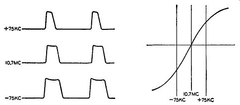
Fig. 9.30. The variation in current pulse duration in the beam gated
tube with frequency modulation.
Fig. 9.31. Discriminator response of the beam-gated tube when connected as shown in Fig. 9.29.
In the gated-beam tube, grids 1 and 3 represent electron gates. When both are open, current passes through the tube. When either one is closed, there is no current flow. In the present instance, the second gate lags be hind the first. Plate-current flow starts with the delayed opening of the second gate and ends with the closing of the first gate. Now, when the in coming signal is unmodulated, and L1C1 of Fig. 9.29 is resonated at the I.F. frequency, the voltage on grid 3 will lag the voltage on grid 1 by 90°. However, when the incoming signal is varying in frequency, the phase lag between the two grid voltages will likewise vary. This, in turn, varies the length of the period during which plate current can flow. (See Fig. 9.30.) Thus, plate current varies with frequency, and the circuit is designed so that the current varies in a linear manner. By placing a resistor in the plate lead, R of Fig. 9.29, we can obtain an audio voltage to feed the audio amplifiers that follow. A typical discriminator response for an FM receiver with a 10.7 -mhz center frequency is shown in Fig. 9.31. Note that this curve does not possess any sharp bends (such as Fig. 9.3 does, for example) at frequencies beyond the range of normal signal deviations. This makes the receiver easier to tune.
In the circuit of Fig. 9.29, a 680-ohm resistor is inserted between the load, R1 and the plate of the tube. By-passing of the I.F. voltage is accomplished by C2, but since this capacitor is placed beyond the 680-ohm resistor, a small I.F. voltage appears at the anode of the tube. Through the interelectrode capacitance that exists between the anode and grid 3, the I.F. voltage developed across the 680-ohm resistor is coupled into L1C1. The phase relations existing in this circuit are such that this feedback voltage aids in driving the tuned circuit.
Bias for grids 1 and 3 is obtained by placing a resistor in the cathode leg of the tube. Since AM rejection, especially at low input signals near the limiting level, is a function of the correct cathode bias, the cathode resistor is made variable. This permits adjustments to be made in the field in order to compensate for tube or component changes.
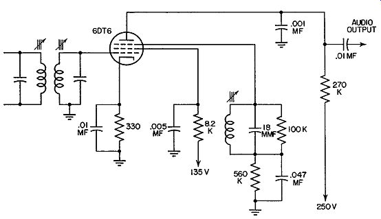
Fig. 9.32. An FM detector circuit using a 6DT6.
The 6DT6 Detector. The 6BN6 tube is, we have seen, of special construction. Recently, another tube has been similarly employed, although its internal structure is very much like an ordinary pentode. However, the only difference is that the control and suppressor grids arc both capable of sharply cutting off the plate current. In this sense they resemble grids 1 and 3 of the 6BN6. The circuit of an FM detector using a 6DT6 (or a 3DT6) is similar to the 6BN6 circuit. (See Fig. 9.32.) So long as the incoming signal is moderate to strong, quadrature-grid detection takes place essentially as it does in the 6BN6 arrangement.
On weak signals, the 6DT6 circuit has a tendency to break into oscillation at the I.F. value. This serves to maintain the detected output signal constant in spite of the fact that weak signals tend to vary consider ably in amplitude due to noise or fading. The oscillations arise because of the feedback which takes place between the suppressor grid and the control grid within the tube. The incoming signal at grid No. 1 locks in with these oscillations and actually causes them to shift in frequency as the modulation moves the signal frequency back and forth. Normal quadrature-grid detection takes place in the oscillating detector. This oscillation boosts the sensitivity of this circuit to weak signals, causing it to deliver a clear output under extremely adverse receiving conditions.
When moderate or strong signals are received, the control grid draws grid current and this loads down the input tuned circuit. This not only kills any tendency to oscillate, but it also broadens the tuning response all of which tends to limit these signals, thereby providing a certain amount of limiter action. In the 6BN6, limiting is achieved within the tube itself.
Tuning in FM Receivers. Proper reception of an FM signal is obtained when the signal is perfectly centered in the R.F. and I.F. tuning circuits.
Since satisfactory location of this center point is necessary if the full ad vantages of FM are to be enjoyed, it is best to incorporate some form of visual indicator into the circuit. To date, two TRIODE PLATE types of indicators have been employed: tuning tubes and tuning meters. The
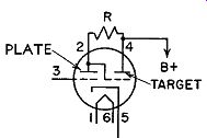
FIG. 9.33. The schematic symbol for a "Magic Eye" tube.
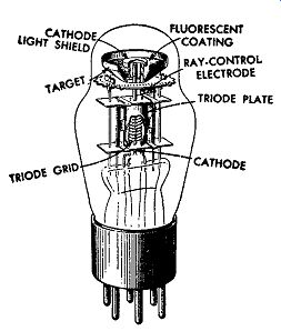
FIG. 9.34. The internal structure of the "Magic Eye" tube
.. tuning tube ( or tuning eye) is a vacuum tube possessing a small fluorescent
screen. From the pattern produced on the screen, it is possible to tell
when the signal is maximum and, sometimes, whether the receiver is exactly
in the center of the channel. The same indications can be obtained with
a tuning meter, this time from the movement of the meter needle.
For a long time, tuning tubes were the most popular form of indicator.
However, recently, there has been an increase in the number of FM receivers using tuning meters. Meters may not be more accurate than tuning tubes (although frequently they are), but their indications are easier for the set user to interpret. On the other hand, meters are more costly, and the less expensive tuning tube often is still preferred.
The following discussion shows typical applications of both types of indicators.
Tuning Tubes. Indications with a tuning tube, such as the 6E5, are obtained visually by means of a fluorescent target. The 6E5 tube contains two main sections: (1) A triode which functions as a d-c amplifier and (2) a fluorescent screen.
In operation, a positive voltage is applied to both the fluorescent screen, known as the target, and the plate of the triode (see Fig. 9.33). Electrons from a cathode which is common to both sections of the tube bombard the target and cause a fluorescent glow. The breakdown illustration in Fig. 9.34 illustrates clearly the common cathode extending through the tube.
In order to have a sector of the 360° of the fluorescent screen serve as the indicator, a thin rod extends up from the triode plate (see Fig. 9.34) and projects into the region between the upper section of the cathode and the fluorescent screen. The rod is known as the ray-control electrode. Since it is attached physically and electrically to the triode plate, it assumes the same potentials as the plate. It is on this attachment that the entire operation of the tube depends.
Referring to Fig. 9.33, when the control grid is biased almost to cut-off, a small current flows to the plate and subsequently through resistor R. The voltage drop across R is very low, placing both the target and the triode plate at almost the same potential. This means, further, that the ray-control electrode projection of the triode plate has practically the same potential as the fluorescent screen.
Electrons leaving the upper section of the cathode are attracted by both the ray-control electrode and the fluorescent screen. Their path is essentially straight, from the cathode to the screen. Thus, the fluorescent screen emits light at all points except directly opposite the thin rod. The electrons are prevented from reaching the screen by the rod and a shadow is observed.
This is shown in Fig. 9.35A.

FIG. 9.35A. The width of the eye when the control grid of the tube is
quite negative.
Fig. 9.35B. The electronic paths in the "Magic Eye" tube when an overlapped pattern is produced.
FIG. 9.35C. The eye opening when the grid becomes more positive.
When the negative voltage on the control grid is increased further, a slight overlapping appears on the fluorescent screen. This is due to the paths taken by the electrons in passing the ray-control electrode on their way to the fluorescent screen. The electrode is nearer the cathode than the fluorescent plate, and it exerts a greater influence over the electrons. Hence, when the electrode reaches the same potential as the screen, which occurs with no plate current in the triode, it attracts more electrons because it is closer to the cathode. Electrons then flow in the manner shown in Fig. 9.35B and produce an overlapped pattern on the fluorescent screen.
For the opposite set of conditions, when the voltage applied to the triode grid becomes less negative, the current flow through the tube and resistance R increases. This raises the voltage drop across R and places the triode plate at a less positive-or more negative-potential than the fluorescent target.
The ray-control electrode also becomes increasingly negative with respect to the fluorescent screen. Electrons leaving the cathode and traveling to the screen will shy away from the ray-control electrode. Thus, very few electrons will impinge on that section of the screen directly behind the ray control. The effect is a dark sector and the "eye" is said to open. The visual effect is indicated in Fig. 9.35C.
In amplitude-modulated receivers, the A.V.C. line is attached directly to the grid and the station tuned in by observing the width of the dark sector on the screen-or, as it is commonly referred to, the shadow. The negative A.V.C. voltage reaches a maximum when the station is correctly tuned in.
This is indicated at the electron-ray tube when the width of the shadow is narrowest. On very strong signals the two light ends of the dark sector not only approach each other but actually overlap.
Connecting the Tuning Eye in the FM Set. In an FM receiver, there are two points where the tuning indicator may be connected. One point is at the limiter grid circuit; the other is at the FM detector.
A simple arrangement is to connect the tuning eye into the grid circuit of the limiter. When two limiters are employed, the connection is made in the grid circuit of the first limiter. Here, the negative voltage developed across the grid-leak resistor is directly proportional to the strength of the incoming signal.
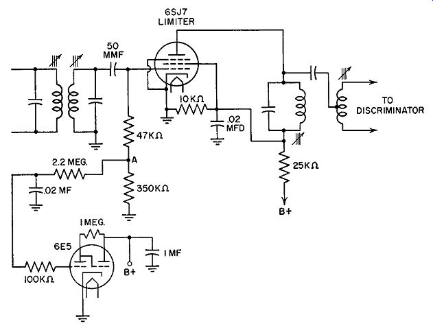
FIG. 9.36. The circuit for connecting a 6E5 tube to the grid of the
limiter stage.
A typical receiver circuit is shown in Fig. 9.36. The voltage across the 350,000 ohm resistor is applied to the grid of a 6E5 tuning-eye tube. Since the voltage at point A is negative with respect to ground, it is of a suitable polarity to be fed to the grid of the 6E5. The stronger the signal, the more negative the voltage at point A and the narrower the eye shadow. In tuning, the listener adjusts the dial until the eye shadow closes as far as it will go.
The 2.2-megohm and 100,000-ohm resistors, together with the 0.02-mf capacitor, form a decoupling unit to prevent the alternating components of the input signal from reaching the grid of the 6E5. The edges of the two sections of the fluorescent target become hazy when this occurs.
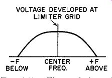
FIG. 9.37. The variation of limiter grid voltage with strong signals.
The disadvantage of the simple arrangement of obtaining the indicator voltage from the limiter grid circuit is due to the fact that, with strong signals, the voltage developed at the grid of the limiter does not permit exact positioning. Fig. 9.37 shows that there is a region about the resonance point where the voltage across the grid-leak resistor of the limiter does not change appreciably. Hence, it becomes possible to tune through a wide range and not obtain a noticeable change in the aperture of the tuning eye. In addition, despite the indications at the grid of the limiter, we still have no way of determining how the discriminator is functioning. Finally, there are receivers which use only partial limiter stages and some other means must be devised if tuning devices arc to be used with these receivers.
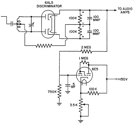
Fig. 9.38. A 6E5 tube connected to the discriminator output.
One method, found in some sets, employs a 6E5 tuning tube that obtains its input from the discriminator output. This is shown in Fig. 9.38. The 6E5 is adjusted to cut-off by variation of the 3500-ohm variable resistor in its cathode circuit. The arm of the 3500-ohm resistor is rotated until the shadow on the fluorescent screen of the 6E5 just closes when no voltage is applied to the grid of the tube. When the set is detuned in one direction, the output from the discriminator is, say, negative and the shadow overlaps.
Detuning in the opposite direction produces a positive voltage and the shadow becomes wider. When the receiver is correctly set, the average voltage from the discriminator is zero and the shadows just close. This is the correct tuning point. The 2-megohm and 750,000-ohm resistors, together with the 0.5-mf capacitor, form a filter that eliminates the audio variations from the discriminator output to the 6E5 and present only an average voltage. The regular audio voltage is still taken from its usual point on the discriminator for the audio stages.
In FM receivers employing ratio detectors, a limiter may not be used.
In this case, a suitable indicating voltage for the tuning eye may be obtained from one of two points in the ratio detector circuit itself. One point, marked
A VC in Figs. 9.24, 9.25, and 9.26, will provide a negative voltage that reaches a negative peak when the station is correctly tuned in. The tuning indicator tube would be connected as shown in Fig. 9.36, except that the end of the 2.2-megohm resistor would go to the A VC point in the ratio detector instead of Point A.
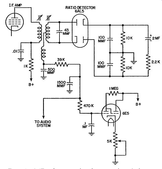
Fig. 9.39. A 6E5 tube connected to the output of a ratio detector.
If the tuning tube is to indicate the center-of-channel, as in Fig. 9.38, it would he connected to that point in the ratio detector where the audio out put is obtained. A typical circuit is shown in Fig. 9.39. Operation of this circuit is identical with the tuning eye circuit in Fig. 9.38.
Other tuning tubes, similar in operation to the 6E5 but possessing differently shaped fluorescent areas, are also available. Thus, the indicating pattern of the EM84/6FG6 is a bar whose length varies with signal strength, becoming longer as the negative voltage on the grid increases. (See Fig. 9.40A.) In the DM70, Fig. 9.40C, the pattern is in the form of an exclamation point. Only the top segment of this pattern varies with signal, the length of the illuminated area decreasing with negative grid voltage. Still another arrangement appears in Fig. 9.40B, this being used in the EM80 tube. In spite of the differences in indication, all of these tubes would be employed in essentially the same manner.
An entirely different type of indicator tube is the 6AF6-G. This contains only an indicator section with two ray electrodes mounted on opposite sides of the cathode and connected to individual base pins. These provide two separate shadow angles in place of the one in the 6E5. Two symmetrically opposite shadow angles are obtained when the two ray-control electrodes are connected together; two unlike patterns are obtained when each ray control electrode is separately connected to a different part of the circuit.
--
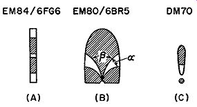
FIG. 9.40. Pattern indications of three tuning tubes. (A) Shaded rectangles
expand and contract lengthwise as negative grid voltage varies. (B) Large
shaded area on top and the two smaller shaded areas below vary in size
as the grid voltage changes. Angle f3 be comes smaller as grid voltage
becomes less negative. This causes angle a to increase. (C) Shaded area
in elongated top segment varies in length as grid voltage is changed.
In each tube, shaded areas (representing fluorescent screens) become
maximum when grid voltage is most negative.
----
In applying the 6AF6-G, it is necessary that each ray electrode receive a fairly good positive voltage, on the order of 60 volts or more. This means that the tube must be tied in to a section of the circuit capable of pro viding this voltage, as well as a fairly large signal swing. One application of the 6AF6-G is shown in Fig. 9.41. The ray electrode at terminal 4 connects to the voltage dropping resistor in the plate circuit of the AM, I.F. amplifier, while the ray electrode at pin No. 3 ties in to a similar point in the FM limiter circuit. From this dual connection, it can be seen that each shadow angle is governed by a different signal, one by AM, the other by FM; therefore, only one of these will be activated when the set is tuned to a signal.
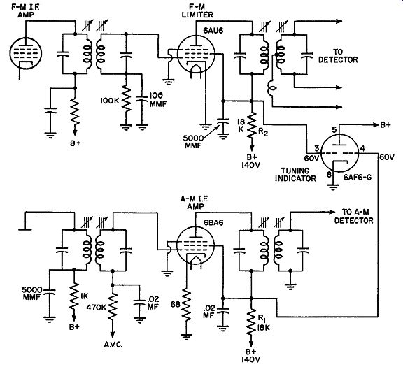
Fig. 9.41. Use of the 6AF6-G tuning indicator in an AM, FM combination
receiver.
Operation of the circuit is fairly simple. When a strong signal is received in the AM circuit, the AVC bias which is fed to the grid of the I.F. amplifier will be most negative. This will cause the plate current to be at its lowest value and the voltage at the top of resistor R1 will be most positive. When the ray electrode is most positive, the shadow is at a minimum.
This, then, is the indication of resonance. A similar action occurs in the FM circuit, except that the limiter tube develops the greatest negative grid bias (by grid-leak action) when a signal is tuned in. This decreases the current flowing through the tube and raises the positive voltage at the top of the resistor R2.
The 6AF6-G tube is, in part, equivalent to that portion of the 6E5 which contains the ray-control electrode. Missing from the 6AF6-G tube is the triode amplifier which is part of the 6E5. As a matter of fact, it will be found that the 6AF6-G is sometimes preceded by two triode amplifiers, one for each ray-control electrode. When this is done, negative grid voltages are required by the amplifiers for tuning indication. This, of course, is similar to the action of the 6E5.
The Electron-Ray Indicator. Another indicator, developed by General Electric, is the 6AL7-GT. This is an electron-ray tube containing a triode and three deflection plates and operating on a principle similar to the "Magic-Eye" tubes. In addition, the tube contains a control grid, located in the triode section of the tube, which can be biased to regulate the brightness of the fluorescent target so that the electron beam can be prevented from reaching the screen when the set is off-station and permitted to reach the screen when the set is tuned to a station. Note that this differs from the action of the control grid in the "Magic-Eye" tubes.
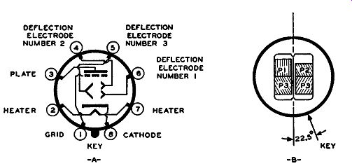
Fig. 9.42. (A) Schematic symbol for the 6AL7-GT tuning indicator. (B)
The fluorescent screen used in this tube.
The fluorescent screen of the tube is rectangular-shaped and divided into quarters. (See Fig. 9.42.) Of the four quarters, however, the top two (shown as P1 and P2 in Fig. 9.42) connect to separate deflection electrodes or plates while the bottom two quarters connect to the same electrode. This arrangement means that, as far as independent variation is concerned, the top two quarters can be varied in size independently of each other whereas the bottom two quarters, being part of the same electrode, will vary in step with each other. The amount of negative bias applied to each electrode controls the size of that portion of the fluorescent screen. The amount of bias on the control grid varies the brightness (but not the size) of all four sections of the fluorescent screen.
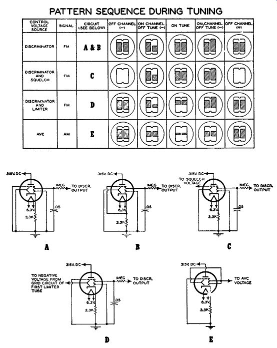
Fig. 9.43. Various applications of the 6AL7-GT tube and the patterns
appearing on its fluorescent target area. (Courtesy G.E.) --- PATTERN
SEQUENCE DURING TUNING.
The chart and circuits in Fig. 9.43 illustrate how the 6AL7-GT indicator can be connected into a circuit and the resulting variation of the fluorescent screen area for off-tune and on-tune conditions. The following explanation will indicate the operation of the tube in each of the circuits shown.
Circuits A and B of Fig. 9.43 show how the tube may be connected so that it operates from the discriminator voltage alone. In each of these two circuits deflection electrodes 1 and 3 are connected to ground, thereby giving them a fixed potential. Hence, none of the fluorescent areas controlled by these electrodes will vary in size, whether the set is tuned to a station or not.
This means that P1 and the left-hand portion of P3 will act as a combined reference area. On the other half of the target, a variable P2 is combined with a fixed P3. P2 is connected to the discriminator and its size will vary according to the voltage it receives (either negative, zero, or positive) from this circuit.
When the station is completely off channel, the discriminator voltage is zero, placing P2 at the same potential as Pl and P3. Hence, both halves of the fluorescent screen will be equal in size. This is true whether the set is off-channel above the desired station or below. Furthermore, it is also true when the set is tuned precisely on frequency. This similarity of indications may appear to be confusing, but actually it is not since music or speech will be heard when the set is correctly tuned to a station and only noise will be obtained for both off-channel positions.
When the set is on channel but off-tune, the average output voltage from the discriminator will be negative on one side of the station and positive on the other side. When the voltage is negative, P2 shrinks in size; when the voltage is positive, P2 becomes elongated. The different connections of the control grid in circuits A and B merely affect the brightness of the total fluorescent area.
In circuit C, we obtain essentially the same tube indications with the exception that a squelch voltage is applied to the control grid, blanking out the fluorescent screen when the receiver is completely off-channel.
In circuit D, P3 receives a negative voltage from the grid circuit of the first limiter tube (if two are used). When the set is completely off-channel, the voltages from the limiter and discriminator are zero, and all electrodes possess the same potential. Hence, the left- and right-hand sides of the target area become equal in size. When the set is on tune, the discriminator voltage is zero, and areas P1 and P2 are equal. At this point, however, the negative voltage from the limiter is quite high, and both quarters of P3 shrink down to practically nothing. On either side of the correct tuning point, the negative grid voltage from the limiter decreases, and the area of P3 increases. However, P2 either will become smaller or larger in size, depending upon which side of the station the set is tuned to.
In circuit E, all deflection electrodes are tied together and all receive the same A.V.C. voltage. Hence, both sides of the target area will vary in step.
This same arrange1aent, with the three electrodes connecting to the grid of the first limiter (if two are used), can serve also as a signal strength meter for FM receivers. If a limiter stage is not used, a practice common with ratio detectors, then the negative voltage may be obtained from the point marked "AVC" in Fig. 9.25 or Fig. 9.27 A. Note, however, that, when the 6AL7-GT is employed in this fashion in FM receivers, its indications are not as useful as they are when employed for center-of-channel location.
[* In a Foster-Seeley detector, the connection would be made to a point such as A in Fig. 9.13. In a balanced ratio detector, the connection would be made to a point such as P, Fig. 9.25. And in an unbalanced ratio detector, the 6AL7-GT would be attached to point C, Fig. 927B.]
Tuning Meters. A tuning meter is generally formed using a 1 ma D'Arsonval type movement. The meter is driven by a triode tube which serves as an amplifier between the meter and the point where the indicating voltage is obtained. The choice of the latter depends on the manner in which the meter is to function. For example, if it is to serve simply to indicate signal strength, then the unit would be connected as shown in Fig. 9.44.
The meter is inserted between R3 and a network of two resistors, R4 and R5.
With no voltage applied to the control grid, R4 is adjusted until the B+ voltage it applies to the meter equals the positive voltage developed across R3. With no voltage difference between the two meter terminals, no current flows through the meter and it indicates zero.
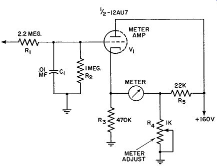
Fig. 9.44. A meter indicating network employed in AM, FM receivers.
The control grid of V 1 is now connected to a point in the circuit where the strength of the incoming signal is revealed by a negative voltage. In an AM receiver, this would be the A.V.C. line. In an FM receiver, this could be the grid of a limiter, or the point marked "A.V.C." in Fig. 9.25 or Fig. 9.27 A. In any event, when the signal is correctly tuned in, the negative voltage applied to the grid of V1 will be highest. This will reduce the current through V1, decreasing the positive voltage developed across R3. If the meter is properly connected, the needle will deflect up-scale.
The same arrangement, using a zero-center meter, will reveal when the center-of-channel of an FM signal is reached. Now R4 is adjusted, with no voltage on the control grid, until the meter needle is at its center zero mark.
The control grid of V1 must now be connected to the FM detector where a zero d-c voltage is developed when the tuner is on-channel, a negative d-c voltage when it is tuned off-channel in one direction and a positive d-c volt-age when it is tuned off-channel in the other direction. Foster-Seeley and ratio detectors can provide such a voltage.
C1 and R1 in Fig. 9.44 function as a d-c filter, removing all signal components from the voltage reaching the grid of the meter amplifier, V1.
Interstation Noise Suppression Systems. As long as a station is tuned in, no difficulty is encountered from background noise. However, as soon as the station is tuned out, the input voltage consists of random noise, too weak to operate the limiter at saturation or beyond. Under these conditions the limiter functions as an amplifier and the amplitude-modulated random voltages produce the familiar loud hiss at the speaker. This is the interstation hubbub, a distracting, hissing, sizzling noise. To eliminate this distraction, many manufacturers have included interstation noise suppression systems generally some simple arrangement that automatically cuts off one or more audio amplifiers when the input signal decreases below a certain level.
The basic idea behind most of these systems involves the use of a tube that is maintained at cut-off as long as sufficient signal voltage is being received. As soon as the input signal decreases, because of a change of dial setting, the flow of electrons is resumed through the tube. This current is made to flow through the first audio-amplifier cathode resistor and biases the tube to cut-off. This condition is maintained until the signal strength of the input of the receiver again increases.
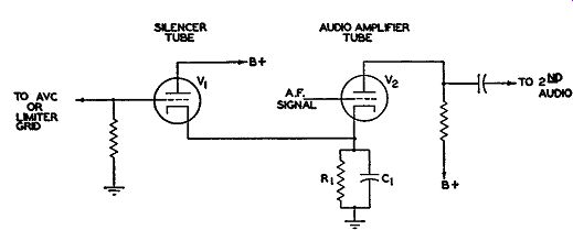
Fig. 9.45. A simple silencer arrangement.
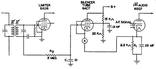
Fig. 9.46. Another possible silencer circuit.
A simple circuit illustration of this principle is shown in Fig. 9.45. V 1 is the silencer, or squelch tube. V 2 is the first audio amplifier. Both tubes have a common cathode resistor and capacitor, R1 and C1. As long as V1 is maintained at cut-off by a negative voltage on its grid, V2 functions normally.
Removal of the negative grid voltage at V1, or at least a decrease to permit an appreciable current to flow, quickly brings V 2 to cut-off because of the excessive voltage appearing across R1. This holding action continues until V1 is again cut off by the application of a negative voltage. Tubes capable of high current flow are chosen for the squelch tube, as this permits decisive control with relatively small negative grid voltages. High-µ. triodes are commonly used. Quite possible, too, is any one of a number of pentodes, al though, in their case, provision must be made for screen voltage.
In an FM receiver, there are two points where the required negative biasing voltage to control the squelch tube may be obtained. One such point is in the grid circuit of the first limiter stage; the other is at the output of the discriminator. In the circuit shown in Fig. 9.46, the grid of the silencer tube is directly connected into the grid circuit of the 6AU6 limiter tube.
The negative voltage developed here is sufficient, with signal reception, to keep the 6AC7 at or beyond cut-off. During these periods, the triode section of the 6SQ7 operates normally as the first audio amplifier. As soon as the negative voltage is removed from the grid of the 6AC7, a high current flows through R1 and biases the 6SQ7 to cut-off. The 6AC7 has a mutual conductance of 9000 micromhos and is capable of large currents with relatively small negative voltage changes on its grid. R2 and C1 form a filter to prevent I.F. currents from reaching the 6AC7. Only the average rectified, or d-c, voltage present on the limiter grid is desired. A switch is provided in the cathode circuit of the 6AC7 to permit the listener to cut out the silencing action if desired. This cutting-out action, for example, might be needed on weak signals when the presence of the silencer could prevent reception.
In Fig. 9.47, the d-c voltage available at the discriminator is utilized for control. If we examine the individual polarity across each of the 100,000 ohm discriminator resistors, we see that point A will always be negative with respect to point B as long as a signal is being received. Note that we are utilizing only the voltage appearing across the lower resistor and not across both resistors as is common for the audio output. The voltage obtained from point A consists of an audio component due to the shifting of the frequency of the signal and a d-c component arising from the amplitude of the incoming carrier. As long as the signal possesses sufficient strength to operate the limiters at saturation, the negative voltage present at point A will be strong enough to keep the silencer tube, a 6J5, at cut-off. This will permit the 6SF5, first audio-amplifier, to function normally. However, when the signal is tuned out, the voltage at point A drops, the 6J5 begins to conduct, and the 6SF5 is prevented from operating. R1 is the resistor common to both triodes. A filter is inserted between point A and the grid of the 6J5 to eliminate the audio component of the voltage at point A and present only a d-c voltage to the silencer.
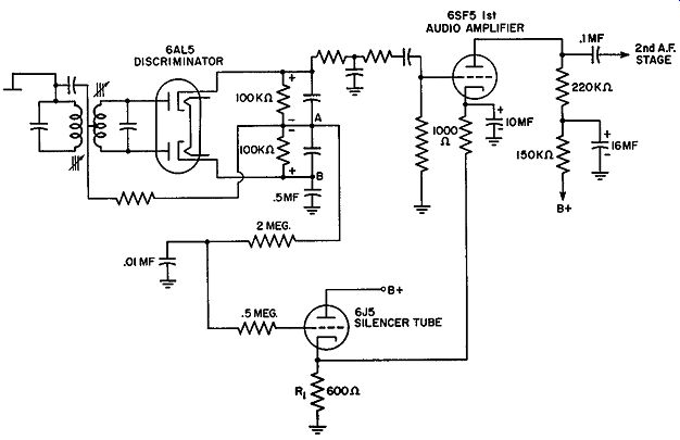
Fig. 9.47. A silencer functioning on the voltage obtained from a discriminator.
Automatic Volume Control (A.V.C.). Automatic volume control is a common feature in the standard broadcast sound receiver. It helps maintain a fairly constant level of output volume and largely counteracts normal changes in signal intensity due to external sources. Within the receiver, A.V.C. also helps to prevent over-loading of the I.F. stages. In FM receivers, the need for A.V.C. is not quite so urgent. As long as the signal is sufficiently strong, it will operate the limiters at saturation, and any change in signal strength beyond this point will have no effect on the output audio fidelity or strength. Also, the I.F. stages preceding the limiter are operated at maximum gain in order to insure saturation at the limiter of all desired signals. Any signal stronger than the average will suffer only amplitude limitation before it reaches the limiter, hut this will not affect its frequency modulation. Since the I.F. amplifiers are operated at maximum gain, signals that are too weak to saturate the limiter are being received below the rated sensitivity of the receiver, and the inclusion of A.V.C. would not prove helpful. As long as the amplitude of the signal being received is of no consequence beyond a certain point, there is little need for A.V.C. In the ratio detector, sensitivity to amplitude modulation is low if the circuit is aligned properly. In addition, many circuit designers incorporate partial or full limiting ahead of the detector as a precautionary measure.
Sometimes, because the ratio detector does possess a source of A.V.C. voltage, it is used. In detectors using 6BN6 or 6DT6 tubes, limiting occurs within the tube and the resulting sensitivity to AM is low enough to provide satisfactory reception on all but very weak signals.
EXAM
1. Contrast the purpose of an AM detector with that of an FM detector. State clearly why each should differ.
2. Draw the schematic diagram of an early type of discriminator which employed two secondary windings.
3. Explain the operation of the circuit drawn for Question 2.
4. Would the foregoing discriminator function if one of the diodes became inoperative? Give the reasons for your answer.
5. Draw the response curve for this early type of discriminator. What would be the effect on the curve if the two tuned secondary circuits were brought closer in frequency? How would this affect the reception of a fully-modulated FM signal?
6. Draw the circuit of a modified discriminator (Foster-Seeley type) widely used today.
7. Describe the operation of the modified discriminator circuit briefly.
8. Indicate the exact function of each component in the discriminator.
9. Are there any modifications that can be made in the circuit? Explain.
10. What limitations of the Foster-Seeley type of discriminator resulted in the development of a ratio detector?
11. Draw the circuit of a ratio detector.
12. Explain briefly the operation of a ratio detector.
13. Are special tuning devices necessary in FM receivers for proper reception of signals? Explain.
14. What types of tuning devices are used? How do they function?
15. Draw the circuit of a simple tuning device connected to the limiter.
16. Explain how the circuit drawn in Question 15 operates.
17. What limitations does this method of connecting a tuning device possess?
18. Draw the schematic diagram of a tuning device connected to the discriminator output.
19. Explain the operation of the circuit drawn for Question 18.
20. Why are interstation noise suppression systems used? What is the basic idea behind most of these systems?
21. Draw the schematic diagram of a simple silencer circuit and explain its operation.
22. What type of tube would be most desirable in silencer networks? Why?
23. Does the silencer network function when a loud burst of interference is being received? Explain your answer.
24. Explain briefly the operation of a beam-gated limiter detector circuit.
+++++++++++