In television broadcasting today the sound transmitter is frequency modulated. Such transmitters are very similar to those employed in regular FM broadcasting. The primary difference between the two systems is that the FCC stipulates 25-khz peak deviation shall constitute 100 percent modulation for television sound transmitters as compared to the 75- khz peak deviation for FM broadcast transmitters.
Consequently, we find that the FM sound signal in television has one third the deviation of regular FM broadcasting for 100 percent modulation.
This reduced deviation and, hence, bandwidth does not put any limitation on the range of audio frequencies that can be passed. As in regular FM broadcasting, the FM sound transmitter in television has to be designed to pass audio frequencies from 50 to 15,000 cycles.
Therefore, high fidelity in the television sound section is still possible even though the peak frequency deviation of output signal is at a maximum of 25 khz. The primary difference between a wide bandwidth and a smaller bandwidth is that, in the latter, the signal-to-noise ratio will be somewhat lower, considering the same amount of amplification in the receiving systems. This can be remedied, if necessary, by increasing the strength of the signal in the i-f stages of the sound channel of the television receiver.
The FCC recommends that the television sound transmitter be designed to operate satisfactorily with a peak frequency deviation of at least 40 khz. This allows for slight amounts of overmodulation in the transmitter.
Frequency Allocations Today there are twelve active commercial television channels, numbered 2 through 13 inclusively. Each channel occupies a 6-mhz band width. These channels are dispersed in the frequency spectrum be-tween 54 to 216 mhz. Frequencies from 72-76 mhz and from 88 to 174 mhz are not part of the television channels. The television spectrum is divided into two bands, the low-frequency band which consists of channels 2 through 6 and occupies frequencies from 54 to 88 mhz (exclusive of 72-76 mhz) and the high-frequency band which consists of channels 7 through 13 and occupies frequencies from 174 to 216 mhz inclusively. Note that the regular FM broadcast band of 88 to 108 mhz lies in between the high and low television bands.
For each television channel the sound as well as the video transmitter operates at fixed carrier frequencies. In Table 4 is a listing of the sound and video carrier frequency as well as the frequency allocation of each commercial television channel. Note that for each channel the sound carrier is 0.25 mhz down from the high end and that the sound and video carriers are separated by exactly 4.5 mhz. This latter factor is very important because upon it depends the operation of intercarrier types of television receivers.
TABLE 4
Fundamental Television Receiver
The television receiver basically consists of a sound section, a video section, a deflection system, and a power-supply system. It is the sound section of this receiver in which we are interested. However, for a complete analysis of this FM sound system we also have to consider the basic video system. An over-all block diagram of these two sections is illustrated in Fig. 10-1. The r-f, oscillator, and mixer sections act as a single front end to both the video and sound signals. The primary difference between these sections of the television receiver and those of the regular FM broadcast receiver is that in the television receiver the tuned circuits must be very broadband in order to accept the 6 -mhz bandwidth for each television channel.
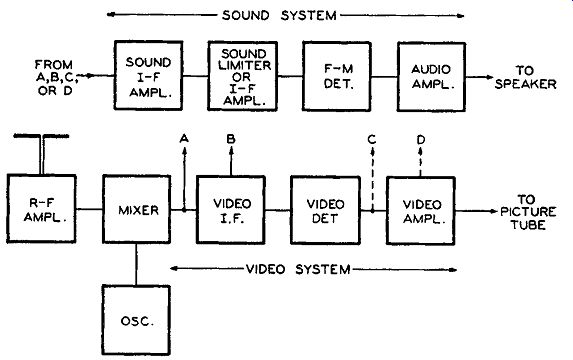
Fig. 10-1. Block diagram of the FM sound and video section of a television
receiver indicating possible points of sound i-f take-off.
The design of the front end is such that, at the output of the mixer tube, both a video and sound i-f signal are selected. The video i-f signal is fed through a series of i-f amplifiers, then through a detector, to video amplifiers, and then to the picture tube. The FM sound i-f signal output from the mixer tube may be fed directly to the sound section of the receiver by some appropriately tuned circuits. This is indicated at A in the drawing. In other receivers the sound i-f signal is fed along with the video i-f signal through one or two video i-f amplifiers before it is fed to the sound system of the receiver. The point of sound i-f signal take-off is indicated at B in the drawing. This latter method imparts additional amplification to the sound i-f signal.
Television receivers that make use of either one of the two methods of i-f sound take-off, as presented by A and B in Fig. 10-1, are commonly referred to as the conventional type of receiver. The exact frequency of the i-f signal in these types of receivers is not a constant factor but depends upon the design of the high-frequency oscillator of the receiver. For other television receivers the FM sound i-f signal follows a completely different path and by the time an i-f signal reaches the sound section of the receiver it has a different frequency than when it first left the mixer tube. This type of television receiver which in effect acts as a double heterodyning system is commonly referred to as the intercarrier type. Let us refer once more to the block diagram of Fig. 10-1 and see why this is so.
For the intercarrier type of receiver the sound i-f signal is passed along with the video i-f signal through the complete series of video i-f amplifiers and also into the video detector tube. This latter stage, which in practically all cases is a simple a-m demodulator, also acts as a mixer to the two i-f signals. In other words, besides demodulating the a-m video i-f signal it also mixes this a-m i-f signal with the FM sound i-f signal to produce a difference beat note between the two.
The conditions of the circuit are such that the difference beat is primarily frequency-modulated with the same intelligence as the input FM sound i-f signal.
This resultant beat note is used as the new FM sound i-f signal of the receiver. The center frequency of this new signal is always 4.5 mhz regardless of what the frequency of the local oscillator is. This is so because the sound and video transmitted carriers are always 4.5 mhz apart and this frequency relationship is maintained even after the heterodyning process in the front-end mixer tube. This 4.5 -mhz sound i-f signal is usually fed to the sound section of the receiver via a 4.5 -mhz tuned circuit. The take-off point for this signal may be from the output of the video detector or after a stage or two of video amplification. This is indicated as points C and D, respectively, in the drawing of Fig. 10-1. In practice the 4.5 -mhz take-off point is usually after a stage or two of video amplification because this also introduces additional amplification to the FM 4.5 -mhz beat note as well as to the video signal. In this latter instance the video amplifiers have to be broad enough to pass this 4.5 -mhz signal.
The sound system of either type of television receiver is very similar to that of an FM broadcast receiver as noted in the block diagram of Fig. 10-1, it essentially consists of a sound i-f amplification section, a limiter if one is needed, an FM detector, and an audio amplification system.
There is not much difference between the sound systems of the two types of television receivers. Except for the differences in intermediate frequencies involved, the primary difference is that the conventional receiver may employ one or more stages of i-f amplification than the intercarrier type.
Sound IF Stages
In intercarrier types of television receivers, the FM sound i-f signal input to the sound section of the receiver is always equal to 4.5 mhz.
This does not mean that the operating sound i-f signal output from the front-end mixer tube is always the same in all intercarrier receivers.
This i-f signal can be any value desired and, as long as it will be passed by the video i-f amplifiers, it will not effect the frequency of the i-f signal being fed to the sound i-f amplifiers. This is in contrast to the sound i-f signals used in the conventional types of receiver where they vary widely. Sound intermediate frequencies ranging anywhere from approximately 20 mhz to 40 mhz are found in today's conventional type receivers. This range is about five to ten times as great as that of inter carrier receivers.
In the majority of cases the sound i-f tuned circuits in both types of television receivers are tuned inductively. The tuning and circuit design of the tuned sound i-f circuits are, however, more critical in the conventional type of receiver because of the much higher frequencies involved. Stray wiring, shunt, and tube capacitances play a very important role in the design of i-f transformers used in the conventional type of receiver. There are cases where tuning is accomplished without a fixed capacitance in the circuit. That is, the inductance is made variable and will form the necessary tuned circuit with the shunt and tube capacitances of the circuits.
The primary function of the i-f amplifiers and transformers in the sound section of a television receiver is the same as in any ordinary superheterodyne receiver. The i-f amplifiers provide a large part of the necessary gain and selectivity needed for the proper operation of the sound system. Even though the peak-to-peak frequency deviation for 100 percent modulation in television sound broadcasting is 50 khz, the band-pass characteristics of many of the i-f transformers are much greater than the 50 khz. This wide transformer bandwidth is necessary in order to allow for any drift in the heterodyne oscillator of the receiver. This is especially so in the conventional type of receiver. The FM sound signal, at 100 percent modulation, occupies less than 1 percent of the television channel. Consequently, if the local oscillator drifts in frequency by a small amount it will cause the reproduced i-f signal output from the mixer tube to fall outside of the acceptable range of a 50- khz wide i-f transformer. By making the band-pass characteristics of the sound i-f transformers much wider than this amount, small drifts in oscillator frequency will not affect the acceptance of the sound i-f signal.
The other basic design requirements of the sound i-f stages of tele vision receivers are the same as that of FM broadcast receivers and need not be discussed again. Staggered tuning is not employed in the sound section. Under-coupled and/or overcoupled i-f transformers are employed where each is tuned to the same frequency. In fact as far as the general run of commercial FM and television broadcast receivers are concerned, staggered tuning can only be found in the video i-f section of television receivers.
The Detector System
The FM detector system employed in the sound section of television receivers functions in exactly the same manner as those found in regular FM broadcast receivers. Only two types of detector systems are used- namely, the limiter-discriminator detector and the ratio detector. There are cases where a limiter tube is used with a ratio detector circuit in order to insure complete rejection of a-m effects in the sound system. In either event the limiter functions in the normal manner as described in Section 7 of this guide.
The FM detector systems of the sound section of television receivers are usually subject to more degrees of amplitude modulation than FM broadcast receivers, primarily because of the presence of the a-m video signal in the receiver. This is even more so in intercarrier receivers because in the mixing process between the a-m video signal and FM sound signal, some a-m effects will always result in the output of the 4.5 -mhz beat note. The degree of a-m interference depends a great deal upon the amplitude of the two i-f signal inputs to the video detector. This is one of the chief reasons why some receivers that employ ratio detectors also have the tube immediately preceding it function as a limiter as well as an i-f amplifier.
"Television - How It Works Volume 2" which accompanies the Rider Television Manual, Volume 2, published by John F. Rider Publisher, Inc., New York, N. Y.
The discriminator and ratio-detector circuits found in television receivers are very much the same as those analyzed in Section 7 of this guide. There is very little difference in their design and they operate in a similar manner. There are, however, some detector circuits that are used in television receivers that are slight modifications of those previously discussed in this guide. Some of these variations, which will be studied now, are not necessarily confined to the sound section of television receivers but may also be used in FM receivers.
Discriminator-Detector Modification
In most FM detector circuits a vacuum tube is used, either a duo diode tube or the two diode sections of a multielement tube is employed. In some television receivers it will be found that a pair of germanium crystals replace the vacuum tube. A typical discriminator circuit in which such crystals are used is illustrated in Fig. 10-2. This circuit is practically the same as that indicated in Fig. 7-26 of Section 7, except that the 1N34 germanium crystals replace the diodes and a resistor is used instead of inductance L. The circuit illustrated in Fig. 10-2 is just one type of detector arrangement that can exist using germanium crystals. The operation of this detector circuit is exactly the same as that discussed for Fig. 7-26.
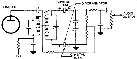
Fig. 10-2. Typical discriminator-detector circuit using 1N34 germanium
crystal diodes for greater electrical stability.
Although 1N34 crystal diodes are more expensive than a duo-diode tube, such as the 6H6 or 6AL5, they offer a number of advantages as compared with the vacuum tubes. A 1N34 crystal diode occupies much less space than the conventional duo diode. With these crystals, sockets are not necessary and they do not require any heater voltage.
Aside from these physical characteristics, crystal diodes such as the 1N34 offer greater electrical stability and thus a better balance is obtained in the discriminator circuit. The total shunt capacitances, such as the input and output tube capacitances and stray capacitances, are less when using germanium crystal diodes than with conventional duo-diode tubes. This is another feature which helps toward better discriminator balance. The positive or plus terminal of the 1N34 crystal is usually the plate of the diode and the negative or minus terminal of the cathode.
Ratio-Detector Modification
There are also some modifications of the ratio-detector circuits previously discussed in this guide. As in any type of ratio-detector and discriminator-detector circuit, two very important operational features are required. One being that the voltage appearing across the primary of the detector transformer should also appear across both diodes and each voltage should be of the same phase, the other is that equal voltages should appear across each half of the center-tapped secondary but 180° out of phase from each other. These features are not readily evident in the modified ratio-detector circuit of Fig. 10-3.
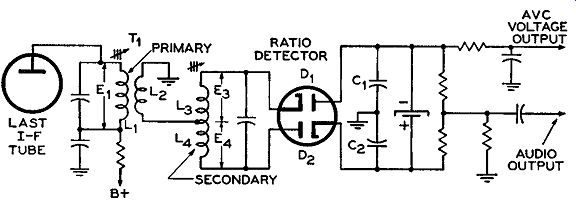
Fig. 10-3. Modified ratio-detector circuit with the secondary (L, and
L,) of the transformer separated from L1 and L2.
This circuit is radically different because coils L1, L2, L3, and L4 are not encased in one shield can as usual. T1 contains only the primary (L1 ) and tertiary (L2 ) coils while the secondary is separated from both these coils. Actually there is little or no inductive coupling between the secondary and the other coils because they are separated at quite some distance on the chassis. Therefore, the voltages that appear across L 3 and L 4 are not due to transformer action as in the circuits analyzed in Section 7.
Coil L1 is closely coupled to coil L2 and by transformer action voltage E 1 appears across L2 but of opposite phase, similar to the circuit of Fig. 7-37. From the diagram of Fig. 10-3, it may not be evident how voltages E3 and E4 appear across their respective inductances L3 and L4 and also how voltage E1 appears across each diode. In order to see this more clearly, only that part of the detector circuit of interest to us is redrawn, and appears in Fig. 10-4.
We know that when a signal is being received, a voltage will be induced into coil L2 from coil L1, which voltage is approximately of the same magnitude as that across L1 because of the close coupling. Since coil L2 has one end tied to the center connection of coils L3 and L4 and the other end grounded, the voltage appearing across it also effectively appears across each diode. The completed circuit is through the ground connection between the balanced capacitors C1 and C2. Since inductances L3 and L4 are equal as well as capacitors C1 and C2, the signal voltage drop across each diode, due to the voltage across L2, is the same.
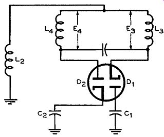
Fig. 10-4. Simplified drawing of the circuit of Fig. 10-3 which illustrates
how voltages E, and E. appear across L. and L,.
Let us analyze the action of the circuit on only one half-cycle of the input signal at a time. When the voltage across L2 is on the positive half-cycle, the plate of diode D2 and the cathode of diode D1 will both have a positive potential, and the cathode of diode D2 and the plate of diode D1 will both have a respective negative potential. Thus diode D1 will not conduct because its plate is less positive than its cathode.
However, diode D2 will conduct because its plate is more positive than its cathode. Consequently, a current will flow in coil L4 and a voltage drop E4 will appear across this coil. This voltage drop is due to conduction current flowing through it and not to induction as was usually the case. However, coils L3 and L4 are usually so closely wound together on one form (it usually is a single center-tapped coil) that there is effectively unity coupling between them. The conduction current flowing through L4 will thus set up magnetic lines of force which will link coil L3 and, hence, induce a voltage in this coil of the same magnitude as that across L4. Thus voltages E3 and E4 equal each other in magnitude. However, due to the method of connection between these two coils, the two equal voltages, E3 and E4, are 180° out of phase with each other. Therefore, we have the same phase conditions between the three voltages (that across L, and E3 and E4), as discussed in the circuits in Section 7.
The induced voltage across L8 will then cause an induced current to flow through its circuit. Consequently, on the positive half-cycle we see that equal but 180° out-of-phase voltages appear across secondary coils L3 and L4. On the negative half-cycle of the signal across L2, the potentials across each diode are interchanged from what they were on the positive half-cycle. This means that diode D1 will conduct first, the conduction current will then flow through coil L3, and thus coil L4 will have an inductive current flowing through it. The magnitude of the voltages across L3 and L4 are the same as that which occurred on the positive half-cycle because each half-cycle is of the same amplitude.
Thus it is seen that during each cycle of input signal, equal but 180° out-of-phase voltages appear across L3 and L4. The Audio System The audio amplifiers and speaker system of the sound section of television receivers are the same as that employed in FM receivers.
Whatever we said regarding this section of the receiver also holds true for television receivers.
In most cases, only a single audio voltage amplifier stage and one stage of audio power output are employed. The voltage amplifier and the FM detector may be both a part of a single multielement tube such as the 6TB. In most cases, the audio output is single-ended (not a push pull arrangement). In those types of television receivers which also contain an a-m receiver and phonograph (or provision for phono graph connection), the same audio system may be employed for each unit.
In quite a few television receivers, the audio system is put to use in helping to regulate certain supply voltages in the receiver. In one particular system, the audio output tube also serves as a voltage regulator. The circuit in question is illustrated in Fig. 10-5. The receiver in which this circuit appears has two supply voltages -- namely, 150 volts and 360 volts. The supply voltages are so distributed that they are used in the appropriate sections of the receiver.
The 150-volt supply is used for the plates and screens of the r-f and video i-f sections of the receiver. The 150-volt supply is also used in conjunction with the 360-volt supply for the sound section of the receiver. The cathodes of this latter section are connected to the 150 volt supply and the plates to the 360-volt supply. Thus, the effective supply voltage on these tubes is 360 volts less 150 volts, or 210 volts.
Since the r-f and video i-f sections of the receiver also use this 150-volt supply, any current variations in these circuits may change this voltage. The voltage-regulator circuit of Fig. 10-5 prevents any such changes. Let us examine the circuit to see how such regulation exists.
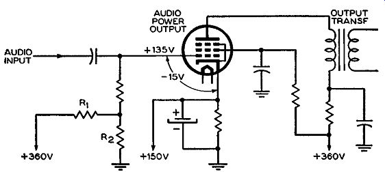
Fig. 10-5. Audio output tube used as a voltage regulator.
You will note that the control grid of the tube is connected to the 360-volt supply through a resistor network. Components R1 and R2 act as a voltage divider to this supply and their values are so chosen that a positive 135 volts appears on the grid of the tube. Since the cathode of the tube is tied to the 150-volt supply, the effective grid bias (i.e., grid-to-cathode voltage) becomes 15 volts negative.
Now, if there is any change in the receiver operation such as if the 150-volt supply is altered, the bias on the audio power output tube will also change. This change in bias naturally causes a change in plate current flow. This, in turn, means that the voltage drop across the cathode resistor will likewise change. The change, however, is such that it will bring the cathode potential back to 150 volts.
If the applied voltage on the cathode increases beyond the 150 volts, the bias on the tube will become more negative because the magnitude of the cathode-to-grid potential is increased. This negative bias increase means a decrease in plate current and, therefore, a decreased voltage drop across the cathode resistor. This reduced voltage across the cathode resistor is just enough to offset the original increase in the applied cathode voltage. On the other hand, if the applied cathode voltage decreases, the negative bias will decrease, plate current will increase, and a greater voltage drop will exist across the cathode resistor. This increased voltage drop is sufficient to bring the potential back to 150 volts.
Supply Voltage
The operating voltages for the sound section of television receivers are obtained in practically all cases from the same low-voltage supply that feeds the rest of the receiver. If the receiver is a-c operated, the supply uses a transformer and vacuum-tube rectifiers and if it is an a-c d-c set, selenium rectifiers or a series bank of high-voltage filament tubes are used.
The tube filaments of the sound section are usually not all fed by the same filament transformer winding. They are almost always used in conjunction with the tube filaments of some other section of the television receiver. For example, the sync, deflection, and audio circuit filaments may all be in parallel and fed from one filament transformer winding. The sound i-f, FM detector, r-f circuits, video i-f and video detector tube filaments may be supplied from another filament trans former winding. There are also cases where the filaments of the complete receiver are in series. In such cases as this, the complete series chain is usually across the a-c line. There are still other cases where the filaments of the receiver are in a series-parallel arrangement and the complete circuit is usually across the a-c line. From what has been said, we find that there are no specific arrangements as to how the filaments of the sound section of television receivers are connected.
FM Broadcast Reception
There are quite a few television receivers that are also designed to receive FM broadcast signals. In most of these cases the FM sound section of the receiver is used for this reception. The station selector of such receivers is usually of the continuously variable type where the frequency change is made by an air core type of variable inductance.
Since the change in inductance is from the low end of the band, 54 mhz, to the high end of the band, 216 mhz, it passes through the FM broadcast band of 88 to 108 mhz. This means that the front end of the television receiver, the r-f amplifier, mixer, and oscillator will also perform the same functions to the FM broadcast signals. Since there is no video signal present, only an FM i-f signal is produced at the output of the mixer and is, consequently, fed to the sound section of the receiver. In such types of receivers the filaments of the unused tubes should be switched out of the circuit during FM broadcast reception. This will insure a minimum amount of interference from these sections and will also help prolong the life of the tubes.
In conventional types of receivers with continuously variable tuners, such a system of FM broadcast reception is designed easily. Very seldom are additional circuit components ever needed when the tele vision receiver is equipped for this method of FM broadcast reception.
However, if the television receiver is of the intercarrier type, a completely different situation exists, even if the receiver does contain a continuously variable tuner. A difficulty arises from the fact that the 4.5 -mhz FM i-f signal needed for the operation of such receivers is based upon the reception of a video signal too. Consequently, the FM sound section of such receivers cannot be used for FM broadcast reception as in the case for the conventional type of television receivers. Even a front-end circuit change in intercarrier receivers is not practical because the resonant frequency of the sound i-f transformer and center frequency of the FM i-f signal output from the mixer tube are different. One possible way the FM sound section of intercarrier television receivers can be used for FM broadcast reception is to use a separate r-f and converter system with the i-f output signal adjusted to 4.5 mhz. Another way in which this may be accomplished is to change the oscillator frequency (by some switching system at the front end) during FM broadcast reception so that the output i-f signal is 4.5 mhz.
Of course, a special 4.5 -mhz sound i-f take-off transformer at the output of the mixer tube would also be needed. However, such cases are not practical.
The band-pass characteristics of the i-f transformers used in the sound section of television receivers is more than adequate to handle the bandwidth characteristics of FM broadcast signals.
Servicing and Alignment
In the servicing of the sound section of television receivers, the technician must bear in mind the fact that this is but one part of a complete receiver and that certain conditions are interrelated among the different sections of the receiver.
It is beyond the scope of this guide to delve into all the different possible defects that usually occur because it will involve a knowledge of how the other parts of the receiver operate. It is the picture reproduction and sound output of the television receiver which are the primary means whereby defective operation of the television receiver is detected. There are certain conditions of picture-tube reproduction that may tell us that the sound section is either defective or causing interference in the video section of the receiver. On the other hand, a distorted or defective sound output from the receiver does not necessarily mean that the sound section of the receiver is directly at fault.
Since the low-voltage power supply is common to all sections of a television receiver, a defect in this power supply will usually be evident in both the sound output and reproduced picture. Consequently, we see that it is not as simple a matter to find out if only the sound section is defective as it would be in FM broadcast receivers.
Extreme care should be exercised in the actual servicing of the sound section because of the frequencies involved. This is especially so in conventional-type receivers where the sound i-f runs as high as 40 mhz. This means that in the replacement of any component parts, the position of parts and the length of the leads used should be duplicated as closely as possible. A change in lead dress may add or subtract to the shunt capacitance of the circuit. It should be remembered that at 40 mhz, a small change in the shunt capacitance of a high-frequency tuned circuit can throw the circuit out of resonance by quite a lot. The use of service instruments for test and measurements must also be done with care. A probe always introduces capacitance into the circuit and may cause erroneous instrument reading.
Most of the information covered in Section 9 on servicing also applies equally well to the sound section of television receivers. however, it should be remembered that the antenna of the television receiver and also the r-f oscillator and mixer sections are common to the video and sound systems of the receiver.
The alignment of the sound section is not much different than that of FM broadcast receivers. As pointed out, there is relatively little difference, if any, between the FM i-f and detector systems of both types of receivers. The alignment of the sound i-f and detector systems of television receivers can be accomplished by any method of visual or meter alignment as covered in Section 8 of this guide. Alignment of the r-f, oscillator, and mixer stages of television receivers is a different proposition because a video-modulated signal, as well as the sound modulated signal, is involved and hence will not be discussed here.
-- A complete analysis of visual alignment of television receivers can be found in Section 16 of the text, "Encyclopedia on Cathode-Ray Oscillo scopes and Their Uses," by John F. Rider and Seymour D. Uslan, John F. Rider Publisher, Inc., New York, N. Y., 1950.
QUESTIONS
SECTION 10
10-1. What is the intermediate frequency of the sound section of intercarrier television receivers?
10-2. a. What is the peak-to-peak frequency deviation for 100 percent modulation in television sound broadcasting? b. How does it compare with that for FM broadcasting?
10-3. a. What is the frequency separation between the carrier frequencies of the sound and video transmitted signals? b. Which transmitted signal is always higher?
10-4. Is the frequency conversion system of television receivers used for both the sound and video section of the receiver?
10-5. Is staggered tuning employed in the sound i-f section of tele vision receivers?
10-6. What types of detector systems are employed in the sound section of television receivers?
10-7. a. Is it necessary that the voltages appearing across both diodes of a detector circuit due to that across the primary be in phase with each other? b. Are the voltages across each half of a center-tapped secondary of a detector transformer out of phase with each other?
10-8. Can FM signals be received by some television receivers? Explain.