There is no doubt that FM is here to stay. The number of FM broadcasting stations now on the air and the number of applications filed for new stations decidedly represent a rapid trend toward this relatively new field. A greater number of broadcasting stations means that the receiver industry will be producing more and more FM receivers. Before long FM receivers will demand as much time of the radio serviceman as a-m receivers do now. Most of the FM receivers now on the market are incorporated in a-m receivers, so that when anything goes wrong, the FM as well as the a-m section has to be considered as the source of trouble.
Many of the troubleshooting methods employed for a-m receivers are also used for FM receivers. Signal tracing, voltage measurements, resistance measurements, and alignment checking are just a few of the common methods used.
A great many troubles encountered in FM receivers are very similar to a-m troubles. Troubleshooting common to both types of receivers will not be discussed, since the average serviceman familiar with a-m receivers can cope with it. Troubleshooting problems which are. considered unique and important for FM receivers will be analyzed in this Section. Most of the problems to be discussed are considered typical by competent radio servicemen who have handled FM receivers of most of the radio manufacturers.
One of the main differences between an FM and an a-m receiver is the range of frequencies involved. Due to the very high frequency nature of FM signals, the troubleshooting procedure of FM sets has to be approached from a different angle. At frequencies around 100 mhz the smallest amounts of inductances and capacitances take effect.
Likewise at high frequencies the effective resistance of a resistor is increased. For these reasons, the instruments used in troubleshooting the receiver should not introduce any stray capacitance or lead inductance effects which may cause improper adjustment of the receiver.
Antenna Relocation
If an FM receiver owner complains that his set has poor reception and if the receiver is located in a service area where the field intensity is weak, the best bet is to check his antenna system. It was pointed out in the Section on receiving antennas that it is considered a necessity to have an external FM antenna erected in areas having weak field intensities. This is to insure adequate signal pickup for proper operation of the receiver. If the FM receiver itself is in proper working order and weak reception exists, then an FM antenna should be erected. There is also the possibility that a complaint of weak reception may be received from the owner of a set already equipped with an external FM antenna. To meet this situation first determine whether the reception is weak on all stations or on only a few; for the problem may be in the orientation of the antenna.
To correct this, it is very helpful to know something about the FM broadcasting stations that cover the area in which the receiver is located. Two things should be known: namely, the strength of the signals at the receiver and also the location of the transmitting antenna.
The receiver may be located in an area where transmitted signals are coming from varied directions; in which case the antenna may be so located that it is broadside to some signals and not to others, thereby causing weak reception on the latter signals. A quick remedy would be to relocate the antenna so that there is a satisfactory compromise among all the signals, in which case adequate reception may be obtained from all the FM stations.
If, with the exception of one or two, most of the stations have a relatively high signal strength in the area of the receiver, the antenna should favor the direction of the signal from these weaker stations.
This will mean a loss in signal pickup on the stronger stations, but their field strengths may be great enough to withstand this reduction in signal pickup.
It is possible that there may be weak reception of most, if not all, of the stations within the area of the receiver. If the receiver itself functions properly, the fault may be with the antenna. If most of these FM stations are coming from locations that are very near each other, the FM receiving antenna may not have its pickup element located broadside to the direction of the signals. If the antenna used is an omnidirectional antenna, there is no advantage in relocating unless it is so placed that its pattern is badly distorted. If reception is still weak on all stations after the antenna orientation has been checked and if the receiver itself is not at fault, the inadequate signal pickup may be due to a mismatch in the antenna system causing a loss in the signal somewhere between the antenna and input to the grid of the first tube. A mismatch, or even a faulty transmission line connection, may cause a loss in energy in all types of antenna systems, thereby causing weak reception.
Image Response
Interference due to image response is more common in a-m receivers than in FM receivers for more reasons than one. First of all, in FM the strength of the desired signal at the detector has to be only ten times as strong as the interfering image signal in order that the interference will not take effect, whereas in a-m the desired signal must be at least 100 times as strong. Secondly, image frequencies are possible within the a-m broadcast band itself, because the highest i.f. commonly used is around 456 khz. In the 88-to-108 -mhz band of FM, image frequencies within the same band are not possible if a 10.7 -mhz or higher i.f. is employed.
Image frequency response, if you recall, means that some undesired signal finds its way into the mixer or converter system of the set and in conjunction with the oscillator signal produces a beat frequency which is equal to the i.f. of the receiver. For example, if an a-m broad cast receiver is tuned to a 600- khz station and if the oscillator is tuned above the incoming desired signals by the i.f., which we shall call 456 khz, the oscillator frequency for this particular setting will be equal to 1056 khz. If an interfering signal of 1512 khz finds its way into the frequency conversion stage, the 1056- khz oscillator will beat with this interfering signal to produce a difference frequency equal to the i.f. In other words, 1512 khz less 1056 khz equals 456 khz which is the i.f.
If you subtract the desired frequency of 600 khz from the image frequency of 1512 khz, the difference frequency will be equal to 912 khz, or twice the i.f. of the receiver. Since these frequencies - 600 khz and 1512 khz - are within the a-m broadcast band, it is seen that such interference can result within the a-m broadcast band itself. To find out whether or not interference due to image response can result on the same band of any receiver, both the i.f. and range of frequencies of that band should be known. If the band of frequencies is less than twice the i.f. involved, image frequency response cannot occur within the band itself; but if it is more than twice the i.f., image frequency interference can result.
The 88-to-108 -mhz FM band in use today has a frequency range of 20 mhz. Consequently, if the i.f. of the receiver is the conventional 10.7 mhz, image frequency response within this FM band cannot result, because 20 mhz is less than twice 10.7 mhz or 21.4 mhz. However, if the i.f. is less than 10 mhz, such as 9.1 mhz, 8.3 mhz, or 4.3 mhz, then on the 88-to-108 -mhz band image response can occur. Therefore, if you are troubled with image frequency response in an FM receiver, a quick check of the i.f. will disclose whether or not the image frequency can come from a signal within the FM band. If the i.f. is 10.7 mhz, as it is in most FM receivers, any image response that may occur will be due to some signal outside the FM band. If the signal is amplitude modulated which it may be, most of the amplitude rejection qualities of FM receivers will be able to eliminate this interference.
In conclusion we can state that interference in FM receivers due to image frequency response is practically nonexistent, due to the high i.f.'s employed and also due to the inherent interference rejecting qualities of the FM receiver.
Signal Tracing
There is no need to elaborate about how important signal tracing methods have been in troubleshooting a-m receivers. Many books have been written upon this subject to acquaint the serviceman with the method of servicing which is still considered the best. There is no reason why signal tracing methods should not also be applied to FM receivers. In fact, they work just as well for FM as for a-m sets. The equipment used need not differ much, except for the frequency range involved. However, there are a few important factors especially pertinent to servicing FM receivers by signal tracing.
An FM receiver can be signal traced with either an a-m or an FM signal generator. Both types are used because a-m signal generators are used to align an FM receiver by the meter method and FM signal generators are used in visual alignment. By bearing in mind how a circuit in the FM receiver responds to an a-m signal, we can readily isolate the section of the receiver that is causing the trouble. When using an FM signal generator in tracing the signal, remember that it is varying in frequency and not in amplitude.
In using signal tracing as a method of servicing, remember that the frequencies involved in the oscillator and r-f section are around 100 mhz and those of the i-f stages about 10 mhz. This makes the situation different from a-m broadcast receivers where the maximum frequency is about 1600 khz. Therefore, care must be taken not to intro duce capacitive or inductive effects which might cause false and erroneous readings.
Signal tracing includes a number of items. All the following items are part of signal tracing, but the procedure does not necessarily mean a progressive test to check all these conditions. For example, it might be necessary to establish whether the signal exists in the circuits where it should exist, whether it is absent from the circuits where it should not exist, and furthermore, whether the signal has the proper level or intensity at certain specific points in the system. Added to the foregoing are such items as frequency, the presence of interfering signals, distortion, overload, hum, and unbalanced signal voltages.
Working with the signal-tracing routine as a means of localizing the defect, we embrace all of the components utilized in the FM receiver. This is so because the function of all of the components of a radio receiver is to secure proper operation of that receiver with respect to the signal and, hence, to show some effect, direct or indirect, upon the signal. Therefore, the process of signal tracing requires a definite knowledge of the manner in which individual components function, in addition to an understanding of the manner in which complete sections of the receiver operate.
Expressed in its simplest terms, the sequence of signal testing is as follows: The test signal is traced through the receiver until some point is reached where it is no longer normal. Supplementary tests are made at the point where the signal departs from normal. Usually the tests include voltage and resistance checks of the various components in the faulty circuit.
Noise
One of the greatest causes of trouble in FM and a-m receivers is the problem of noise. A set plays well one day, and the next day starts to develop some distortion in the speaker output which the set owner describes as noise. The causes of noise output of a receiver are numerous. Noise can result from such factors as bad tubes, distortion in the audio output circuit, faulty filtering networks, a-chum pickup, outside interference, and defective resistors (thermal noise), as well as a host of other factors. Many of these noise troubles have been encountered in a-m servicing problems but, due to the high-frequency nature of FM, two causes of noise warrant further discussion. These are r-f tube noise and resistor noise ( thermal noise) .
R-F Tube Noise
Most tube noise in FM receivers comes from the r-f and/or converter stages. Noises in tubes arise from a number of different factors, but the two greatest causes of tube noise are shot effect and thermal agitation. The amount of noise contributed by both these types can be computed mathematically, and consequently the relative signal-to-noise capacities of the tube can be figured out. For the purposes of this guide it is enough to indicate that such tube noises do exist, and the derivation of these formulas is irrelevant.
To understand the meaning of shot effect, the nature of the current flow inside a tube should be known. The electron current flow within a tube is not a continuous even flow of electrons, as is often believed.
The current flow actually is a movement of individually distinct particles emitted from the cathode in random fashion. Because of this random motion of the electrons, a machine gun or raindrop effect results when they impinge upon the plate. The noise arising from this is termed shot effect.
The current flow within a conductor, likewise, consists of an irregular movement of individually distinct particles. This causes random voltage fluctuations within the conductor which are a direct function of the temperature. These voltage variations likewise cause noise in amplifier tubes, called thermal agitation, and limit the amplifying qualities of the tube.
Both these types of noise are directly proportional to the band of frequencies over which the tube is operating. Therefore, we can well realize that r-f and converter tubes will be noisier when used in FM receivers than when used in a-m broadcast receivers. In FM receivers the frequency bandwidth varies from 150 to 250 khz, whereas the a-m band-width is from 8 to 15 khz. This difference in frequency band width increases the noise factor of r-f tubes from what it is for AM by a factor of about 20. Many FM receivers have been found to be noisy due to noisy r-f tubes. Such tubes when tested by most tube checkers will probably indicate satisfactory operation, but will still be noisy. A quick method of testing is to tap the tube while the set is in operation, and if the tube is bad the noise will probably increase. Another quick method is to replace the tube by a new one and see if the reception is still noisy.
Faulty components within the tube also may be the cause of r-f tube noise. Any slight amount of vibration will cause a modulation effect of the signal inside the tube and, hence, a noisy or distorted output may result.
Pentagrid converter tubes also produce noise voltages as a result of random fluctuations of current and, due to space current effects and the great number of grids present, the noise produced is relatively quite high. The less the number of grids used, the lower the noise voltage. This is one of the main reasons why separate tubes are used as oscillators and mixers. A triode used as a mixer has a very low noise component in its output, and consequently a high signal-to-noise ratio.
Many tubes are manufactured today to take care of these numerous defects of noise in the usual r-f and converter tube. The higher the g,,. of the tube, the less its noise output, therefore many of the new tubes are designed to have a high g,,.. A typical pentagrid converter tube specially designed for work on the 88-to-108 -mhz FM band is the 6SB7Y. Resistor Noise Thermal agitation noise exists in any conductor as well as in a tube.
Two factors which determine the amount of noise voltage due to thermal agitation are the temperature and band of frequencies involved.
The amount of noise voltage is directly proportional to both of them, therefore, the higher the temperature and the wider the band of frequencies, the greater the thermal noise voltage.
From this analysis of thermal agitation it is very easy to conceive of carbon resistors contributing to thermal noise voltage, especially when they are used in FM circuits as voltage dropping resistors where the power dissipation (temperature effect) and wide band of frequencies also contribute to this noise. Consequently, thermal noise from resistors will be in greater evidence in FM receivers than in a-m receivers.
Certain FM receivers have been found in which the resistors were so noisy that they had to be changed. Undoubtedly, noise from thermal agitation is involved, but this is not the sole cause of noise produced by the resistor. Another contributing noise from the resistor is a result of the construction of carbon resistors.
Carbon resistors are composed of finely divided granules. When a direct current passes through the resistor, the values of contact resistance between adjacent granules fluctuate, producing a high noise effect. This "fluctuation noise" is much greater than the inherent thermal agitation of the resistor. The amount of noise is released as an effective noise voltage and is directly proportional to the current flowing through the resistor. Increasing the value of the resistance tends to increase this noise voltage at a faster rate than the increase in resistance.
Since direct current causes this noise, such resistors will be trouble some when used as plate loads, plate decoupling networks, and in similar circuits where the noise voltage may be coupled to another tube and then amplified along with the signal.
Oscillator Troubles
One of the biggest troubles in FM receivers is oscillator drift. Many a set owner has complained to his serviceman or his dealer that he has to retune his FM receiver every now and then to keep it on station. This is a serious situation because, if a customer cannot be satisfied with a virtually new receiver, he will lose faith in FM altogether.
The set owner wants all the good features of his a-m receiver, including oscillator stability, plus the· wonderful features of FM that are advertised when he purchases an FM receiver. Consequently, if one of the first troubles he encounters is oscillator drift, he will be annoyed because of his continued efforts at retuning the receiver.
Many of the complaints of oscillator drift are due not to the failure of some component, but to the bad choice of design components in the original manufacture of the unit. It has been found that improperly mounted ganged tuning capacitors have caused oscillator instability.
Also, the mechanical design of receivers has resulted in vibrations with operation of the set which change the frequency of the oscillator.
When such factors are the cause of oscillator instability, it is advisable that the receiver be returned to the manufacturer or some authorized dealer. This is recommended because manufacturers often become aware of these defects after the set has been marketed and devise some special remedy to correct the oscillator drift.
A primary reason why the oscillator circuit drifts so readily is the frequency involved. It should be constantly kept in mind that the oscillator frequency is around 100 mhz and any slight variation in circuit components will markedly change the frequency of the oscillator.
Change in effective component values may be small, but this small change can be great enough to cause the oscillator to drift in frequency. It has been found that changing the oscillator tube can cause a frequency shift, because the new tube is not an exact match to the old one and may introduce different capacitive effects. In addition some individual tubes are less stable than others of the same type. It may, therefore, be desirable to try several tubes for the oscillator to find one which gives the best results.

Fig. 9-1. Two ways a gimmick is used as a coupling capacitor. In (A)
the gimmick forms an effective capacitance between it and the tank coil;
in (B) the gimmick couples some of the oscillator voltage from the oscillator
tank circuit to the mixer grid.
As in a-m receivers, one of the main causes of faulty oscillator operation is a bad oscillator coupling capacitor. Since the frequency involved is so high, the amount of capacitance needed to couple the oscillator voltage from a separate oscillator tube to the grid of the mixer is very small. Even a mica capacitor may become defective enough to cause some trouble in the oscillator circuit. Most cases of oscillator trouble due to the coupling capacitor result from the capacitor becoming open.
Some oscillator circuits use the simple expedient of a piece of twisted wire called a "gimmick" to form an effective capacitance between the oscillator and mixer tube or within the oscillator section of a converter tube. A gimmick is a piece of wire, one end of which is usually soldered to one circuit. The other end remains open but is twisted around another circuit. An effective capacitance is formed between the twisted section of the wire and the component it is twisted around.
The value of the capacitance is quite small, but for the high frequencies of FM it is ample for coupling. The open end of the gimmick may become loose or detached, which will probably affect the oscillator system to a point where very little or no oscillator voltage is fed to the r-f grid of the mixer tube.
If a loose wire is found in inspecting such a circuit, check the schematic diagram to see if a gimmick is represented. Two typical schematics of a gimmick used as a coupling capacitor are illustrated in Fig. 9-1 (A) and (B). In Fig. 9-1 (A) the gimmick forms an effective capacitance between its open coil and the tank circuit of the oscillator section of a converter tube. In Fig. 9-1 (B) the gimmick couples some of the oscillator voltage from the oscillator grid tank circuit to the r-f grid circuit of the mixer tube.
There have been quite a number of complaints about loose permeability tuning slugs in the oscillator coils. Due to some vibration within the receiver, the permeability tuning slug wobbles inside the core.
This produces slight changes in the value of the effective inductance in accordance with the degree of movement. If the tuning slug happens to wobble at an audio rate, the oscillator frequency will become modulated at this rate. This audio modulation will be reproduced with the regular signal and consequently will cause a distorted output. This type of action is called a microphonic effect. The main reason the tuning slug vibrates is that the space separation between the tuning slug and the coil form is larger than it should be, and, therefore, the tuning slug has room to vibrate. The primary cause of this large space is the tolerance specifications of the tuning slug and coil form. The tuning slugs are manufactured with only a minus tolerance, and the coil forms with only a plus tolerance. This means that when a tuning slug has the limit of its minus tolerance, its diameter will be smallest and when a coil form has the limit of its plus tolerance its inside diameter will be greatest. Therefore, a fairly large space will be left between two such units used together, giving the tuning slug room to move.
The usual remedy is to employ some method of locking the screw adjustment of the tuning slug in place after adjustment, so that the slug itself will have less chance to vibrate. Another correction is to place some type of washer on the shafts of the tuning slugs. If these do not help much, it is best to replace the complete oscillator coil unit, making sure that the new one is not similarly defective.
Microphonic Ganged Capacitors
Mechanical vibration of the oscillator tuning slug discussed in the preceding section is one type of microphonism in circuits. Microphonism is the term applied to mechanical movement of circuit components or the elements within a vacuum tube that produces modulation effects which causes a howling noise in the speaker output. Microphonism is, therefore, divided into two categories: tube microphonism and circuit microphonism. A microphonic tube can be detected by tapping it while in operation and listening to the output of a receiver. A noisy or howling effect will be heard which gradually dies out. Microphonism is more frequent in circuit components than in tubes. One instance of this is the mechanical vibration of the oscillator tuning slug previously mentioned.
A very important characteristic of mechanical systems should be known relative to understanding why certain vibrations do occur.
Mechanical systems are like electrical systems in that resonance effects exist in both. The mass and elasticity of all mechanical systems have their counterparts in the inductance and capacitance of electric systems and, consequently, mechanical oscillations may occur.
Such mechanical oscillations have occurred in the ganged tuning capacitor arrangement of certain FM receivers causing microphonism in this unit. These mechanical oscillations are due to acoustic feed back from the speaker to the ganged capacitors. This acoustic feedback can be coupled to the ganged capacitors through two mediums, through the receiver cabinet itself or through the medium of the air inside the cabinet. The speaker vibrations are propagated to the ganged capacitors through either one, or both, of the afore-mentioned mediums causing mechanical oscillations in the capacitors. If the chassis is removed from the cabinet, the microphonic effect will disappear, indicating that the mechanical oscillations are caused by coupling the speaker vibrations through the mediums mentioned.
These mechanical oscillations occur primarily in the stator plates of the capacitors. This howl is more pronounced at higher audio volumes because of the increased acoustic feedback from the speaker.
A number of methods have been devised to get rid of this microphonic howl, such as special mounting of the ganged capacitors and/or speaker on special rubber or shockproof mounting. Inserting special pieces of cardboard or some other type of baffle to eliminate the acoustic feedback through the medium of the air is another method to reduce the microphonism. Recent tests have showed that the ganged capacitor microphonism is due mostly to acoustic feedback through the medium of the cabinet which is difficult to correct.
Servicing Through Alignment
One of the quickest methods of finding faults within a certain part of a receiver is through the principle of alignment. This is even truer of FM receivers because of the involved method of alignment compared with a-m receivers. Many defects found in FM receivers may be the result of a badly aligned stage, such as the i-f or detector. Most FM sets that are relatively new and have not been handled overmuch are probably in good alignment, but receivers that have been exposed once or twice to someone who knows a "little" about radio, as the next door neighbor, may be thrown out of alignment as a result of his sparse knowledge of high-frequency networks and FM receiver alignment. It should be remembered time and time again that the frequency involved in FM receivers is quite different from a-m receivers, and consequently special precautions have to be taken.
Upon examination of a faulty FM receiver, the serviceman, by virtue of his experience, can tell whether or not the receiver is aligned properly. By listening to the output of the speaker while tuning in different stations the serviceman has a ready method of telling if the set is out of alignment. Another quick method is to feed an FM i-f signal to the converter signal grid and place a meter across the proper component for the different detector systems. If the meter does not read zero, something between the i-f and detector stage is throwing the set out of alignment.
The misalignment may be due to the i-f or detector transformers not being properly tuned, or it may be due to a faulty component inside these circuits. Whichever is so, the defect can be quickly found by aligning the receiver. Any method of alignment outlined in Section 8 can be used, provided the alignment procedure is the correct one with respect to the FM detector circuit employed. If the alignment for each stage from the r-f down to the second detector circuit is corrected, the set should operate normally. However, if in the process of aligning some stage of the receiver, the desired meter reading ( or proper picture in the oscilloscope if visual alignment is used) cannot be obtained, no matter what the manipulation of the trimmer adjustment, the trouble is probably due to a faulty component within the circuit tested.
The circuit should then be checked further by means of resistance, voltage, and continuity tests to locate the fault. This method of servicing by alignment is very similar to signal tracing, in fact it actually consists of tracing the signal.
After the i-f and detector stages have been properly aligned and any faults corrected, the receiver may still be misaligned due to the front end r-f and oscillator stages. With the other stages already aligned, these latter two stages should be checked for alignment to see which stage is at fault.
A number of defects have been located by alignment checking in some of the circuits between the i-f and detectors stage. Discriminator transformers have been found to have an open secondary winding.
Also, the coupling capacitor (if any is used) between the primary winding and secondary circuit of the discriminator may be open. With both faults, the improper voltages are impressed across the diode of the discriminator tube, thus preventing correct detector action. Similar defects have been found in ratio detector transformers.
Another defect found is in the iron slugs used for permeability tuning i-f and detector transformers. Practically all these tuning slugs are made from powdered iron bound together to form solid tuning slugs. In a number of FM receivers these tuning slugs have been found to fall apart, either by breakdown of the powdered iron or by the loosening of the screw part from the slug.
Limiter stages have caused quite a bit of trouble which is difficult at first to trace to this stage. A badly operated limiter stage may result in distortion of the a-f output from the discriminator stage. The most frequent cause of such trouble and types of limiter trouble is a bad limiter tube. A tube tester may not indicate that the tube is defective, but it may not function properly as a limiter. A new tube should be substituted, and the stage realigned to determine whether the tube is the cause of trouble.
Another frequent cause of trouble in the limiter stage is that some how the plate and/or screen voltages on the tube change, which changes the threshold input signal to the stage. If these supply voltages increase, the limiting action of the stage decreases, because a higher threshold signal input is needed for proper limiting action. The change in supply voltages may be great enough so that the tube functions more as an i-f amplifier than a limiter. This results in most of the a-m variation of the input signal being detected by the discriminator, causing distortion in the output.
A primary cause of limiter supply voltage change is a faulty plate load resistor, or the substitution of a plate load resistor that is far off the required value.
Cathode Lead Inductances
The signal to the r-f stages of all receivers should be as large as possible for the best possible signal-to-noise ratio of the receiver. Be sides this, it is also desirable in FM sets to provide enough voltage so that, through the gain of the receiver, the proper threshold voltages necessary for the operation of certain stages will be maintained. At the very high frequencies involved in FM, many an r-f tube has caused a reduction in the signal input to its grid circuit. This reduction in signal input is due to the inherent inductance in the cathode lead within the tube. By cathode lead inductance is meant the actual inductance of the cathode wires within the tube itself. Fig. 9-2. A typical r-f stage in which L represents the inductance of the cathode lead. The arrows indicate the direction of the high-frequency currents flow.
The reduction in signal input is explained as follows: The high-frequency currents that flow in the tube travel from cathode to plate, then through ground, and back to the cathode again.
The schematic of Fig. 9-2 is a typical r-f stage in which L represents the inductance of the cathode lead wires of the tube itself (assuming that the cathode pin is grounded right at its base and inductance due to wiring is not present). The flow of the plate current is indicated by the arrows in the diagram where the high-frequency currents travel from the cathode to the plate and then through the plate tank circuit through capacitor C to ground. It returns to the cathode via ground to complete the path. The cathode lead inductance L presents a reactance to these high-frequency currents and causes an r-f voltage drop, Ee in Fig. 9-2, across the inductance. This r-f voltage drop is effectively impressed across the grid circuit as an inverse feedback voltage, similar to the effect which occurs when a cathode resistor is unbypassed, except that this voltage is 90° out of phase with the grid voltage. Since Ee is an inverse feedback voltage to the grid circuit, then the effective voltage on the grid is equal to the vector difference between the input voltage E and the cathode lead voltage drop Ee. The greater the value of L, the less will be the effective signal input.
Due to the high frequencies involved in FM and television, special tubes have been designed wherein the effects of cathode lead inductance are minimized. The cathodes of these tubes are designed with two separate wires leading to the base of the tube, each wire going to a separate pin. Schematic illustrations of such tubes are shown in Fig. 9-3. In Fig. 9-3 (A) the tube schematic can either rep resent a 6SG7 semi-remote cutoff tube or a 6SH7 sharp cutoff tube, both r-f amplifiers. These are regular sized tubes with octal bases. In Fig. 9-3 (B) the tube schematic is representative of either the 6AG5 or 6AK5 miniature type tube which are both sharp cutoff r-f amplifiers. From these tube schematics it is seen that two cathode leads are used in each.
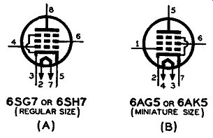
Fig. 9-3. Schematic symbols of special vacuum tubes designed for the high
frequencies encountered in FM and television. Note that the tubes have
two leads to the cathode.
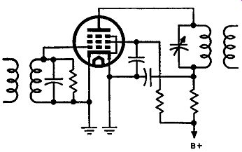
Fig. 9-4. An r-f stage employing a tube, such as shown in Fig. 9-3,
in which one of the cathode leads is used for the control-grid circuit
and the other for the plate and screen-grid r-f current return.
With two such leads, one can be employed as the plate current return and the other for the control grid circuit. The use of such a tube is illustrated in the drawing of Fig. 9-4. In this circuit the plate and screen currents flow through their respective bypass capacitors to the cathode lead to which they are connected. The grid has its tuned circuit returned to ground through the connections to its particular cathode lead. From these connections, it is seen that the r-f components of plate and screen current flow through only the right cathode lead, thereby being completely separated from the grid circuit. Consequently, inverse feedback, due to the cathode lead inductance and r-f plate and screen circuit currents, is no longer effective in the grid circuit. The d-c components of the plate and screen currents upon returning to the cathode of the tube split up and flow through both cathode leads.
In wiring a circuit containing such dual cathode leads, the cathode lead to which the suppressor is tied is used as the plate return lead, because the suppressor has a rather high capacitance to the plate, and the other cathode lead becomes the grid return. Some manufacturers stress the importance of these pin connections in their schematics by indicating the cathode lead to which the plate and screen bypass capacitors should be wired, as well as the cathode lead to which the grid return circuit is wired. However, the majority of schematics show just the cathode grounded without indicating which cathode lead is used for the plate or grid circuit. In rewiring such circuits, the foregoing procedure for connecting the proper components to the different cathode leads should always be followed to avoid any possibility of a decrease in signal input. If the same cathode lead is used for both the plate and grid r-f return, degeneration may occur, reducing the effective input signal.
Critical Lead Dress
Throughout this Section on servicing we have constantly mentioned that high frequencies are involved and that great care is demanded in testing the FM receiver. One of the most critical factors in the manufacture of FM receivers is the wiring of the chassis. In wiring FM receivers, the leads are kept as short as possible to avoid introducing any added inductance into the circuit and also to reduce stray capacitances. At frequencies around 100 mhz, and even at 10 mhz, the introduction of added inductance and stray capacitance due to the wiring, may form tuned circuits that will resonate and cause undesired oscillations. The added inductance of such leads may also cause regeneration or degeneration within certain parts of the FM receiver, according to the location of the leads.
The fact that these undesired effects manifest themselves more readily at high frequencies emphasizes how careful the manufacturing of the sets must be. Besides engineering the electrical design of an FM receiver satisfactorily, it is important to engineer the correct mechanical arrangement of chassis layout and wiring. So far as the engineer is concerned, there is a definite reason for every defect that occurs, and it is his job to eliminate the defect before the FM receiver is given the final OK for production.
Most FM receivers that come off the assembly line are supposed to have a wiring layout that will not cause any undesired oscillations or feedback. Many manufacturers stipulate in the service notes of their FM receivers that the radio serviceman should be careful not to change the lengths or the positions of the wiring layout. After any repair is completed, the wiring layout should be as nearly as possible a duplicate of what came off the assembly line. Some manufacturers even go to the extreme of giving in detail an outline of dressing of certain leads. The designers of the receivers realize the importance of such information, because of the trouble that can occur if the wiring is different. This critical lead dress should be a must, especially in those receivers where moving a lead a fraction of an inch may detune the set a little or even may cause undesired feedback. A wiring dia gram is often included with the service data which can be used as source of information on the exact location of the wires.
In some instances it is difficult to get rid of certain inductive or stray capacitive effects in a certain part of a circuit, so, to avoid the possibility of parasitic oscillations, resistors are often placed in the plate and/or grid circuit of certain stages. Commonly known as parasitic resistors, they are usually small in value, very seldom exceeding 1000 ohms.
It is known that the leads coming out of i-f transformers are usually quite close together due to the small construction of the transformer.
There have been a number of cases where these i-f leads were so situated that regenerative feedback occurred in an i-f amplifier, causing it to break into oscillations. The correct dressing of the i-f leads can reduce or even eliminate the feedback, so that the i-f tube will no longer oscillate.
QUESTIONS
SECTION 9
9-1. Is image frequency response a common cause of trouble within the FM bands of today? Explain.
9-2. In servicing FM receivers, why must special care be taken not to introduce stray capacitances or lead inductances? 9- 3. a. Name four common causes of noise in a receiver.
9-4.
9-5.
9- 6.
b. What are two very common causes of noise in an FM receiver? Why is tube noise much greater in FM receivers than in a-m receivers? Which produces a higher noise voltage-a pentagrid tube or a triode tube? Why? What factor besides the frequency bandwidth influences the amount of therm?,l agitation noise in a tube or conductor?
9-7. a. What type of noise other than thermal noise is evident in a carbon resistor? To what is it due?
b. Which of the two resistor noises is greater?
9. 8. a. Why do permeability tuning slugs sometimes vibrate when subject to some external force?
b. Describe a remedy for the vibration of these slugs other than changing the complete coil unit.
9- 9. Define microphonism.
9-10. What is the chief cause of microphonics in ganged tuning capacitors?
9-11. What is a quick method (other than by ear) of determining whether a part of the i-f or detector section of an FM receiver is out of alignment?
9-12. What is a frequent cause of improper operation of a limiter stage, assuming the limiter tube itself to be all right?
9-13. Cathode lead inductance of a typical r-f stage may cause a reduction in gain of the stage. Why is this possible?
9-14. Why is a wiring diagram of an FM receiver considered very important to a radio serviceman?