The second half of his guide will deal primarily with FM reception and receivers. Previous Sections have dealt with the underlying theory of FM, FM transmitters, and the transmission of FM signals. This practical path was chosen as the one that would develop the most coherent picture of FM Consequently, the fundamentals of the different types of modulation were presented first and then the theory of FM and p-m signals. Once these ideas were established, simple circuits generating FM and p-m signals were discussed. Naturally following this was the discussion of the relative features of FM transmitters, both from a theoretical viewpoint and in terms of those in actual use today for wide- and narrow-band FM The general discussion of the transmitter more or less followed the path of the signal, starting with the oscillator-modulator section and working forward to the power stages of the transmitter. To continue this progressive discussion, FM transmitting antennas were discussed next. With the FM signal at the antenna, the final topic in the analysis was the transmission of FM signals as they were radiated from the transmitting antenna.
To follow the progress of the FM signal, the next thing to discuss would be the reception of these FM signals by the FM receiver. Thus, this Section will deal with FM receiving antennas, and in the next Section the FM receiver will be analyzed in the same manner that the FM transmitter was.
The Signal Pickup
Before going into the physical makeup of FM antennas, some pertinent factors relative to the received signal should be known. In this respect FM simplifies the antenna problem, because the FM receiver can discriminate against noise and other types of interference. It was mentioned previously that in AM the signal-to-noise ratio has to be at least 100 to 1, but in FM the ratio need only be 2 to 1 for proper reception without interference. No matter what the interference -- whether noise or an undesired a-m or FM signal-a desired FM signal that is twice as strong as the interfering signal is sufficient for proper reception. The only exception is in the case of an undesired FM signal on the same carrier frequency; in this case, the ratio must be at least 10 to 1.
The first physical element in the receiving system that the FM signal comes in contact with is the FM receiving antenna. It has often been said that an FM receiver is only as good as its antenna. But authorities have also held that a piece of wire will serve as an FM antenna, or even that no antenna is needed. These contradictory statements arise from the fact that good reception of FM has been attained using just straight pieces of wire, and thus, the necessity of an FM antenna is disputed. However, the only cases of such reception are of the particular kind where the FM receiver happens to be located in a very favorable region with respect to some of the FM broadcasting antennas. The signal strength is then relatively high and good reception may be obtained without the use of a normal FM receiving antenna. In most other installations it has been shown that FM reception is definitely improved with the proper type of antenna.
At points which are a considerable distance from the transmitter, but within the service range of the transmitter, the signal pickup of a conventional single wire is usually so small that the signal-to-noise ratio is quite low and, consequently noise-free reception is not obtained. If you are in doubt whether to use an FM antenna in your location and if you do not know too much about the surrounding terrain and where the FM broadcasting antennas are located, then it is definitely advisable to use an FM receiving antenna.
The nature of the transmitted FM signal is a criterion in orienting the FM receiving antenna to obtain sufficient signal pickup for proper reception. The transmitting antenna must employ horizontal polarization. This necessitates the orientation of the FM receiving antenna in a horizontal position for maximum signal pickup from the passing FM waves. More will be said later about the orientation of the FM receiving antennas.
The antenna generally employed for FM reception is a single half wave dipole or some combination of half-wave dipoles. All types of FM receiving antennas are designed to perform two main functions, namely, obtaining the necessary signal pickup and supplying an output impedance that can be properly matched to the receiver for maximum energy transfer. The different types of receiving antennas perform these functions in one manner or another, as will be seen later.
When we refer to a signal-to-noise ratio at the input to the FM antenna, the noise factor does not include any tube or thermal noise relative to the radio circuit. Actually, therefore, two noise components have to be taken into account when the FM signal reaches the detector circuit of the receiver. One of the components results from the noises and interfering signals picked up directly by the FM antenna, and the other is attributed to the inherent noise characteristics of the components within the receiver itself. Since it is difficult to reduce the inherent noise within the receiver, the best thing to do is either to reduce the noise pickup by the antenna system or to increase its signal pickup, so that the signal-to-noise ratio of the FM signal just before the detector stage of the FM receiver will be high.
To understand why a half-wave dipole is used as the basis of the FM antenna, it is necessary to understand something about the voltage and current distribution, antenna resistances, resonance conditions, and the like with respect to such types of antennas.
Voltage and Current Distribution
In choosing the type of antenna for FM reception, as well as other types of reception, the voltage and current distribution along the antenna must be known for an understanding of the reason a certain antenna is used. In this respect, let us examine the full-wavelength straight-wire antenna as seen in Fig. 6-1. A full-wavelength straight-wire antenna with standing current and voltage waves. Note that at the mid-point of the antenna the current is a minimum and the voltage a maximum.
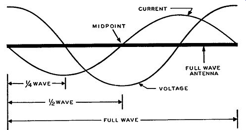
Fig. 6-1. The distribution is such that at the ends of the wire the
current is a minimum and the voltage a maximum. Due to certain characteristic
phenomena of open wires used as antennas, such as that appearing in Fig.
6-1, standing waves of both voltage and current exist along these antennas.
By standing waves is meant the following: A radio-frequency wave traveling
to the ends of the antenna will be reflected back to its starting point.
The reflected wave will meet the original (so-called incident wave) in
such a manner that the individual voltage and current curves of these
waves will add algebraically such that voltage and current waves always
exist on the antenna. These waves are referred to as standing waves.
Antennas in general are referred to as radiating elements, or a series
of such elements, and for the antenna to be a good radiating element
(or receiving element), standing waves should exist on it.
Fig. 6-1 shows the standing wave distribution for a full-wavelength antenna. Distribution of the voltage and current is sinusoidal. Since the voltage and current are represented by sine waves, it is evident that they change polarity at certain points along the full-wavelength wire. The current is a maximum and the voltage zero at one-quarter of a wavelength from either end of the wire. Since the full wavelength of wire represents one complete cycle (360 degrees of electrical length of either voltage or current), the standing waves of voltage and current are said to be 90° out of phase. This 90° phase difference is the same as saying that the reversals of polarity of the voltage and current waves occur one-quarter of a wavelength apart.
The numerous qualities of an antenna apply to both transmitting and receiving antennas, so that those properties discussed under receiving antennas apply equally well to transmitting antennas and vice versa. Consequently, when we talk about the voltage and current distribution of the standing waves on one type of receiving antenna, it applies equally well to the same antenna when used for transmitting purposes.
However, the transmission line used with the antenna should have no standing waves on it, so that the line will not radiate any of the energy but rather transfer it to the receiver. If standing waves do exist on the transmission line, some of the energy picked up by the antenna will be lost from the line as this energy is transferred to the FM receiver input. In order to make the transmission line a non radiating element having no standing waves (that is, no reflection of the signal), the line must be terminated in its characteristic impedance. This means that the impedance of the transmission line must be properly matched to the impedance of the FM receiving antenna and also to the input of the FM receiver. The standing wave ratios quoted by antenna manufacturers include the loss introduced by the trans mission line; the lower the standing wave ratio, therefore, the better the antenna and transmission line setup.
The Half-Wave Dipole Antenna
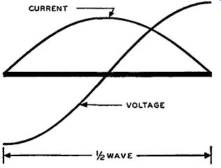
Fig. 6-2. The current and voltage distribution along a half-wave antenna.
Note that at the ends the current is a minimum and the voltage a maximum.
Compare with Fig. 6-1.
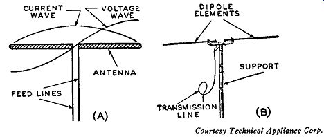
Fig. 6-3. Current and voltage distribution in a half-wave dipole antenna
(A). In (B) is shown a typical dipole antenna, its transmission line,
and a method of support.
Let us now consider a half wavelength of wire or just half that in Fig. 6-1. This half-wave wire is illustrated in Fig. 6-2 and is generally representative of the current and voltage distribution of the half- wave dipole antennas used with many FM receivers. A half-wave antenna is often referred to as just a dipole antenna. The terminology (dipole) for these antennas has originated from the fact that voltage distribution along the half-wave antenna is such that at the ends of the antenna the voltages are of opposite polarity (that is, positive and negative charges). This is readily evidenced by the half cycle of voltage in Fig. 6-2. Since the half-wave dipole antenna is the basic type used in FM receivers, let us examine some of its characteristics as shown in Fig. 6-2. At any one instant, the current standing wave is of the same polarity at all points, and there is, ideally, zero current at the antenna ends with maximum current, which is referred to as a current loop, at the center of the dipole at one-quarter of a wave length from either end. The voltage changes polarity, and the change is such that there is, ideally, zero voltage at the center of the dipole, one-quarter wavelength from either end. At the ends of the dipole, the voltage is a maximum, but the voltage at one end is of opposite polarity to the voltage at the other end.
A drawing of a half-wave dipole antenna is illustrated in Fig. 6-3 (A) along with the waves of voltage and current distribution. In Fig. 6-3 (B) is a picture of a typical half-wave dipole antenna as used today. The half-wave dipole antennas illustrated are those that have center lead-ins and are termed current-fed antennas, because the feed-in lead is at a current loop or maximum. Half-wave antennas can also be end-fed, but FM receiving antennas are center-fed dipoles.
For proper reception, the half-wave dipole antenna should have a length approximately equal to one-half of a wavelength at the center frequency of the frequency spectrum it is to receive. Consequently, the length of each section should be about one-fourth of the wave length of the middle frequency which the antenna is designed to receive.
Antenna Resistances
All the power input to a transmitting antenna is dissipated in one form or another. The so-called resistances of an antenna determine how this power is dissipated. Any antenna, whether it is used for receiving or transmitting, effectively contains two types of antenna resistance. One type is the usual ohmic resistance of the metal parts of the antenna, often called the real resistance; the other type is often called the imaginary or radiation resistance. In other words, we are concerned with two types of power, the power dissipated due to the actual ohmic resistance of the antenna and the power radiated from the antenna. The former power is readily understandable and, from this, the ohmic resistance is conceivable. The resistance dissipating the latter portion of the power is not, in reality, a physical resistance in the sense that the other one is and, hence, often is known as the imaginary or radiation resistance of an antenna. Consequently, when there is talk of power dissipation of an antenna, the I^2R total power loss should be understood to encompass both types of resistances.
Resistance R is the series combination of the ohmic resistance of the antenna and the radiation resistance of the antenna.
In most types of antennas the ohmic resistance is much smaller than the radiation resistance, so that practically all the power is dissipated through the radiation resistance. For a half-wave dipole antenna in free space (that is, no intervening objects including ground effects, buildings, mountains, etc.) the radiation resistance is found to be equal to approximately 73 ohms. The actual value of radiation resistance of the simple dipoles, as used, varies somewhat away from 73 ohms, depending on the exact length of the dipole and presence of other physical factors.
Fig. 6-4. A half-wave dipole antenna (A) and its equivalent series resonant circuit (B), where the resistive component R is primarily the radiation resistance of the antenna.
Resonance and Impedance
The half-wave antenna behaves very much like a tuned circuit. The antenna has inductive, capacitive, and resistive components, but they are all distributed throughout the antenna in contrast to the lumped L, C, and R components in the regular tank circuit. The simple half wave dipole antenna that is center tapped, behaves like a series resonant circuit. This is shown in Fig. 6-4 where L, C, and R represent the inductive, capacitive, and resistive components respectively. The resistive component is primarily the radiation resistance of the antenna since the real or ohmic resistance is relatively very small, even at the increased. value it has at high frequencies.
If the dipole is approximately a half wavelength long, or about one quarter wavelength on either side of the center tap, the antenna will act as a series resonant circuit to the frequency for which it is a half wave antenna. In a series resonant circuit the impedance is a minimum and purely resistive, the current a maximum, and the voltage a minimum. This is also seen from Fig. 6-4 where, at the center point of the half-wave antenna, the current is a maximum and the voltage a minimum. At other points along the antenna the impedance is not purely resistive because it encompasses some reactance. This is due to the changing relationship of the voltage and current standing waves and, therefore, the impedance is greater away from the center point, being a maximum at either end of the half-wave antenna due to the minimum value of current and maximum value of voltage.
Impedance Matching
So that the maximum amount of energy pickup will be transferred from the half-wave antenna to the receiver input, the antenna has to be properly "impedance-matched" to the receiver input. A fair idea of impedance matching can be had from Fig. 6-5. Looking in the direction of the input tube of the FM receiver, through the primary of the input transformer, we see an impedance equal to Z1 ; and looking in the direction of the transmission line and antenna, we see an impedance of Z2, and for maximum energy transfer Z1 should equal Z2. Under this condition the maximum amount of energy possible, not all the energy, will be transferred from the antenna to the grid of the first tube. For the best match to occur, the transmission line should first be impedance matched to the antenna. Then these units through the medium of the receiver input transformer should be matched to the input impedance of the first tube. If there is any mismatch, there will be a loss of energy, and the maximum possible amount of energy will not be transferred.
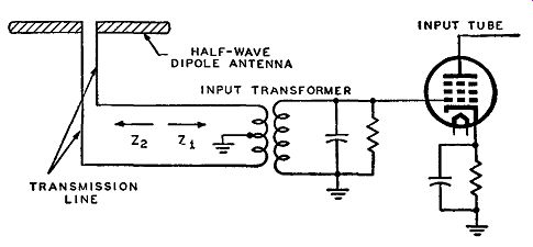
Fig. 6-5. In order to effect a maximum transfer of energy from the antenna
to the control-grid of the r-f amplifier tube, the impedance Z2 of the
transmission line and antenna should equal the impedance Z1 seen looking
into the primary of the input transformer.
As has been pointed out, the input impedance at the center of the half-wave dipole ideally is a pure resistance and equal to 73 ohms. In practice, this value of input impedance of the dipole can vary any where from 50 to 100 ohms as a result of such varying physical factors as the construction of the antenna, the obstacles near the antenna, and its height. A very simple impedance match to such an antenna is made by using a twisted-pair transmission line (usually, ordinary rubber-insulated wire) for the feeder section, as shown in Fig. 6-6.
The so-called characteristic impedance of such a transmission line is somewhere around 75 ohms. If different types of wire are chosen for the twisted line, and if the physical hookups to the antenna can be varied somewhat, the impedance of this transmission line can be varied on either side of 75 ohms for the desired impedance match.
Beside giving a good impedance match, this type of line minimizes pickup by the lead-in due to the twisting effect and closeness of spacing between each individual wire, and thus noise pickup by the trans mission line is reduced.
Where the antenna and line are properly matched, the input trans former of the receiver should have an impedance approximately equal to that of the line or antenna. For example, if the antenna resistance and characteristic impedance of the line are each about 100 ohms, then looking into the primary of the input transformer, toward the first tube of the receiver, the impedance seen should also be 100 ohms. Under these circumstances, the maximum amount of energy transfer will be made from antenna to receiver.
Fig. 6-6. In order to match the impedance of a half-wave dipole antenna with that of the transmission line, the latter can be formed of twisted pair, which has a characteristic impedance of approximately 75 ohms.
TWISTED PAIR-- TRANSMISSION LINE
In reality, almost any good type of balanced transmission line, besides the simple twisted pair, can be used to match the antenna as long as the characteristic impedance of the line is close to the radiation resistance of the antenna. Many receivers use FM antennas sup plied by outside manufacturers; some receivers are not directly sup plied with an FM antenna, which must be bought separately. In the latter case knowledge of the input impedance of the receiver input transformer is necessary to secure the proper impedance match. Many FM receivers today have an input impedance equal to about 300 ohms, so that the transmission line and antenna have to be properly matched to this 300-ohm impedance for proper energy transfer. Transmission lines with a characteristic impedance of 300 ohms would normally be used to match the line to the transformer, but the 300-ohm line would be mismatched to, for example, a 75-ohm simple half-wave dipole.
Some mismatch can be tolerated under certain conditions. First of all, let it be understood that for maximum efficiency the transmission line should match the impedance of the antenna to the input impedance of the receiver. However, a certain amount of mismatch is allowable provided that satisfactory performance of the FM receiver is obtained. Most FM receivers are sensitive enough to suffer a certain amount of energy loss in the received signal and still operate satisfactorily. This means that if there is a small amount of impedance mismatch between the antenna and receiver there will be a certain amount of energy lost by the setting up of standing waves in the transmission line and if this loss is small, it can be tolerated. Even though mismatching by as high as a 4 to 1 ratio has resulted in so called satisfactory receiver performance, this type of mismatch is definitely undesirable and should be avoided wherever possible. Since most antenna and transmission line manufacturers list the impedances of their products, it should be quite easy to obtain a match between the antenna and receiver. The difficulty in the complete matching process is in knowing the input impedance of the FM receivers. We have stated that a great many of these receivers have an input impedance equal to approximately 300 ohms, but the impedance of some differs from this. Since very few receiver manufacturers list the input impedance of their sets, it is readily seen that it is difficult to effect a complete impedance match when normally it is necessary to guess the input impedance of the receiver.
If the mismatch is too great, there may not be enough signal input to the FM receiver to overcome the inherent noise of the receiver.
The signal-to-noise ratio will be low, and the reproduced audio signal will be noisy and incoherent.
It has been stated that for the best reception the line should be matched to the antenna. However, in many instances simple dipoles of 75-ohms input impedance have been used with 300-ohm trans mission lines, yet the signal input to the FM receiver has been enough for proper reception. With this mismatch of 4 to 1 the set still operates satisfactorily. Many FM antenna manufacturing companies stipulate that, if a 300-ohm transmission line is used with their simple half-wave dipole antennas which have an input impedance around 75 ohms, proper reception will still be attained. Knowledge of the construction, the Q, and the impedance of the dipole is necessary to understand completely how such a mismatch can be tolerated.
The input of a simple dipole is, as mentioned, about 75 ohms and resistive in nature. This impedance varies from the center to either end, with the impedance at the ends being a maximum and some where in the vicinity of 2500 ohms. Since this is so, if the antenna can be tapped at some point away from the center, where the impedance is about 300 ohms, we have a good place to match a 300-ohm line.
This procedure is somewhat impractical, but the same effect is obtained in another way. The 75-ohm impedance that appears at the center of the dipole antenna is measured at the frequency for which the antenna is cut. On either side of this center frequency the impedance of the antenna at the center leads will increase - the amount of increase being determined by the frequency change. Thus an impedance mismatch of 4 to 1 for a 300-ohm line attached to a simple half-wave dipole antenna occurs only at the center frequency for which the antenna is cut; on either side of this frequency the impedance increases and, therefore, the impedance mismatch decreases.
Therefore, for these off-resonance frequencies the dipole antenna does not create a 4-to-1 mismatch with a 300-ohm transmission line. However, this 4-to-1 mismatch still exists at the center frequency to which the antenna is cut, but if the antenna is cut to a frequency which has a relatively strong field in the vicinity of the antenna, the input signal may be strong enough to overcome the loss the mismatch entails and, hence, reception at this frequency may be satisfactory.
However, variations of the simple half-wave dipole antenna and variations in transmission line hookups exist, so that impedance matching can be closely attained. There are folded dipoles, dipoles with reflectors, folded dipoles with reflectors, specially constructed simple half-wave dipoles that change the effective radiation resistance, and other unique types of dipole arrangements. Analysis of some of these types of FM receiving antennas is made later.
For any combination of transmission line and antenna, the smaller the length of the line, the less will be the line losses, no matter how well it is impedance matched. lf the line must be long, due to the location of the antenna, low-loss transmission lines should be used to prevent excessive reduction in the signal reaching the receiver.
In conclusion, it may be said that, although correct impedance matching will give the best over-all performance, the primary purpose in most FM antenna installations is to obtain the necessary voltage input to operate the receiver satisfactorily. This may be attained even though a mismatch exists.
Q of Antenna
The inductance and resistance of a straight piece of round wire will decrease, as the diameter of the wire increases. In other words, both L and R are inverse functions of the diameter of the wire. However, at operating frequencies of about 100 mhz for the FM band, the inductance decreases at a faster rate than the resistance for changes in diameter.
Since the Q of a circuit or a wire may be defined as the ratio of inductive reactance to resistance, the Q of the dipole is seen to de crease as its diameter increases. This is due to the fact that the inductance and, hence, the inductive reactance decreases at a much faster rate than the resistance as a result of the diameter increase.
This is the same as saying that the resistance effectively increases with respect to the inductive reactance. Consequently, it can be said that the Q of a dipole antenna is an inverse function of its diameter. The inductive reactance, and hence the Q of a wire, increases with increase in wire length, but for the foregoing analysis of the Q of an antenna the length of the dipole, as well as the frequency of operation, is considered constant. The lower the number of wire used for the dipole, the greater will be the diameter and hence the lower the Q. Since the FM band is quite wide, the FM antenna should have as broad a response as possible, in order to receive all the signals with little or no discrimination. By lowering the Q of the antenna it is possible to secure a fairly broad-band characteristic. However, since a reduction in Q "flattens" out the response characteristic, there is also a reduction in signal pickup. Consequently, a compromise has to be effected between the tolerable loss in signal pickup and the reduction in Q.
The Folded Dipole
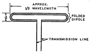
Fig. 6-7. A folded half wave dipole antenna, where d, the distance between the two half-wave sections, is small in comparison to the wavelength.
The folded dipole antenna has a great advantage over the simple dipole antenna in that it exhibits a much higher impedance, thus allowing for a better impedance match to receivers having 300-ohm inputs. In effect a folded dipole is the simple half-wave antenna illustrated in Fig. 6-3 (A) with another half-wave antenna section joined to it at the ends. A typical folded dipole is shown in Fig. 6-7.
From this drawing the folded dipole is seen to be about a full wave-length of wire (or appropriate tubing or rod) bent so that it takes on approximately the shape shown in Fig. 6-7. In Fig. 6-8 are shown three typical folded-dipole FM antennas as used today. Those shown in parts (A) and (B) are typical outdoor folded dipoles, while that shown in part (C), although suitable for outdoor use (with proper mechanical support), is especially useful as an indoor antenna. This latter antenna can be placed under a rug, in a closet, or some other convenient place in the home. It is made completely out of 300-ohm twin-lead transmission line, and can be simply constructed, as follows:
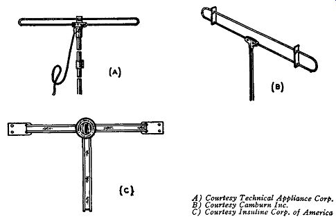
Fig. 6-8. Three types of folded dipole antennas. Those illustrated in
(A) and (B) are for outdoor use and that in (C) is for indoor or outdoor
use.
Take about five feet of 300-ohm twin-lead transmission line and strip away some of the plastic insulator from the ends. Next, twist together and solder the two bare leads on each end, as shown in Fig. 6-9. Then center cut one lead of the twin line and strip away the insulation from each cut end to half the distance between the parallel wires of the transmission line. Finally bend these two bare pieces of wire at right angles at the beginning of the insulator. This part of the antenna represents the folded dipole. Next, take another piece of the 300-ohm twin lead and strip off some of the plastic insulator at one end, so that the two twin leads are bare. This latter twin lead represents the transmission line, and it is usually any length that will make its wiring to the receiver input most convenient, but the shorter the better. Solder these two bare leads to those of the center part of the folded dipole as shown in Fig. 6-9.
Let us now return to a study of the folded dipole in general and see how this type of antenna increases the input impedance compared with a simple half-wave antenna. The folded dipole is similar to an autotransformer where the primary of the transformer is analogous to that part of the folded dipole which has the transmission line attached to it and the secondary of the transformer is analogous to the other half-wave section of the folded dipole. Accordingly it is readily seen that a mutual impedance exists between both half-wave sections of the folded dipole in the same way that mutual inductance exists between the windings of a transformer.
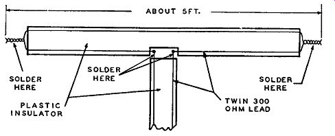
Fig. 6-9. Constructional details of a folded dipole antenna made from
a 300-ohm twin-lead transmission line.
Each individual half-wave section of the folded dipole is considered as a resonant half-wave antenna and fundamentally resistive at the resonant frequency. This is the same as having both the primary and secondary of the transformer tuned to the same resonant frequency in which the impedance of each will be resistive in nature.
This means that looking into the tapped portion of the folded dipole the complete impedance seen is the sum of the tapped half-wave section plus the reflected impedance from the other half-wave section.
Reflected impedance means that, because of mutual impedance between both half-wave sections of the folded dipole, the effective impedance of the primary is changed. This reflected impedance is mathematically equal to the square of the mutual impedance (which is purely reactive in nature) divided by the impedance of the untapped half-wave section. When multiplying the mutual reactance by itself, the result is a purely resistive component, and since the impedance of the untapped half-wave section of the folded dipole is resistive (at resonance), the reflected impedance is, also, effectively resistive. Since the impedance of the tapped half-wave section is also resistive, then the total input impedance of the complete antenna system, as seen from the feed-in half-wave section, under the above conditions of resonance, is resistive.
Since the distance d separating the two half-wave sections of the folded dipole is much smaller than the half-wave length of the antenna, the mutual impedance is considered to approach the maximum possible value. In other words, using the analogy of the transformer again, the coefficient of coupling of the half-wave sections of the folded dipole is said to be approximately unity. Since each individual half-wave section has its own so-called self-impedance, similar to the self-inductance of the windings of a transformer, the total self impedance of both sections (since they are connected) is equal to the sum of their individual self-impedances. The total self-impedance of the folded dipole is not the complete impedance, because the folded dipole antenna impedance as a whole takes into account the mutual impedance as well as the total self-impedance. The wire, rod, or tubing used for both half-wave sections is usually made of the same material, so that the self-impedance of both half-wave sections are about the same, neglecting the small difference caused by the slight spacing of the feed-in section of the half-wave element that has the transmission line attached.
For an autotransformer wired in series aiding, the total inductance of the unit is equal to the sum of the individual self-inductances plus twice the value of the mutual inductance. If the individual self inductances are equal and if the coefficient of coupling is unity, the value of the mutual inductance will be the same as either self-inductance. Under these circumstances, the total inductance of the auto transformer is equal to four times the self-inductance of one part of the winding.
The same is true, for the most part, of the folded dipole. The individual self-impedances of the half-wave sections are about equal, and the coefficient of coupling between these sections is considered to be unity, so that the mutual impedance is the same as either individual self-impedance. The total input impedance for the folded dipole is, therefore, the sum of the individual self-impedance plus twice the mutual impedance. Consequently, the total input impedance of the folded dipole is equal to four times the value of either self impedance. For the half-wave folded dipole these impedances are resistive, as previously mentioned, and, thus, the total input resistance of the folded dipole is equal to four times the input resistance of a single half-wave section of the folded dipole. Since a simple half wave dipole antenna has approximately the same input resistance as a single half-wave section of the folded dipole, the input resistance of a folded dipole is about four times as great as that for a simple half wave dipole.
Under ideal conditions the input resistance of a half-wave dipole is equal to about 75 ohms. So that under similar conditions the input resistance of the folded dipole is equal to 4 X 75 or 300 ohms. Thus for FM receivers having a 300-ohm input impedance a 300-ohm transmission line can be used to match the folded dipole to the receiver for maximum energy transfer, Orientation of FM Receiving Antennas As mentioned previously, according to FCC regulations the FM broadcasting antenna has to be horizontally polarized. In special cases the FCC allows polarization in other than the horizontal plane, but these are few in number. Where such a transmitting station exists, the receiving antenna should be oriented in a slanting or diagonal manner, so that both horizontally and vertically polarized signals can be picked up.
Horizontal polarization is more favorable than vertical polarization, because certain interference phenomena, such as ignition interference, are often polarized very strongly in the vertical direction. Consequently, the horizontal polarization provides a better signal-to-noise ratio, that is, helps the antenna discriminate against noise in favor of the signal pickup.
In horizontal polarization, the electric field (the electric lines of force) of the transmitted signal is parallel to the ground or horizontal.
The use of horizontal polarization reduces the effects of the atmospheric layers which attenuate the high-frequency signals used in FM broadcasting. Because of the horizontal polarization of the radiated FM signals, the radiating elements of the FM receiving antenna must be in a position to receive the maximum possible signal pickup. Most FM receiving antennas, especially in installations containing dipole elements, are so oriented that the radiating elements are horizontally situated.
To receive the maximum adequate signal from the directive antennas, the dipole receiving antenna should be oriented at right angles to the direction of the FM transmitting antenna. Since a number of FM stations, located in different places, cover the same area, the amount of signal pickup by the receiver antenna will differ for each FM station. The receiving antenna should be placed broadside to the directed rays of the transmitting antenna for which the signal pickup is weakest. The receiving antenna thus serves its most useful purpose in trying to obtain equalized signal pickup as nearly as possible for all of the FM stations in its area.
Dipole with a Reflector
In many localities the FM signal pickup required for proper reception is greater than that obtainable with a half-wave dipole or folded dipole antenna alone, so that something has to be done to increase the signal pickup. This is especially necessary when the receiver is located at a great distance away from the transmitting antennas. Since the signal surrounds the antenna, it is easily realized that signal energy exists at points other than the immediate vicinity of the dipole itself.
This leads to the idea that, if some of this signal energy from the surrounding area could be directed toward the antenna, the antenna would effectively have a greater signal input.
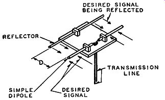
Fig. 6-10. In order to increase the pickup, a reflector element is
placed behind the dipole in the same plane at a distance D, that is between
one tenth and one-quarter of the wavelength for which the dipole is cut.
To increase this signal pickup effectively, the antenna employed is equipped with a "reflector" element. This is shown in Fig. 6-10 where a simple half-wave dipole is shown and placed behind this dipole, in the same plane as the dipole, is the reflector element. This reflector conductor is usually of the same material as the dipole itself, and mathematically it should be slightly longer than one-half wavelength.
The reflector should be placed on the side of the receiving antenna away from the transmitting antenna from which the signal is to be received. This means that the desired signal will be approaching the antenna dipole in the direction indicated in Fig. 6-10. That part of the signal that passes the dipole and hits the reflector conductor will be reflected back to be picked up by the dipole.
The distance D that the reflector is spaced from the dipole is a factor in the amount of increased signal pickup, and it is usually somewhere from one-tenth to one-quarter of a wavelength away from the feed-in dipole element. Most manufacturers specify the spacing in their ser vice instructions accompanying the antenna. This is to make sure that the reflected signal picked up by the receiving dipole is aiding the signal directly picked up by the same dipole, so that the maximum possible total energy pickup is available.
The way in which the signal is increased can also be compared with transformer action. A certain amount of mutual impedance exists between the dipole and reflector, determined primarily by the distance separating the elements and the self-impedance of the elements.
In brief, when the signal hits the reflector, a voltage is induced which causes a corresponding current to flow in the reflector. This reflector current, by analogous transformer action, induces a voltage into the lead-in dipole element, the magnitude depending upon the mutual impedance and the phase relation of the voltage depending upon the spacings between the elements, which is often one-quarter wave length. Thus, it is seen how a receiver antenna with a reflector can have an effective increase in signal pickup over a half-wave antenna without a reflector.
Since a mutual impedance exists between the elements and since the signal pickup is increased, the effective input impedance is altered.
The exact value of the change in the antenna's input impedance depends upon the degree of coupling, the value of mutual impedance between the elements and, hence, the amount of reflected impedance.
When used with a simple half-wave dipole or folded dipole, the reflector usually decreases the input impedance, so that, besides increasing the signal pickup, the reflector can change the input impedance to, perhaps, a better impedance match from the antenna to the receiver.
When used with a reflector, half-wave antennas become unidirectional (that is, become more directional to signal pickup in one direction than any other) in that there is little signal pickup from the reflector side of the arrangement.
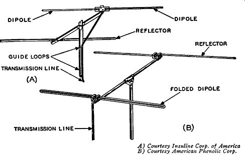
Fig. 6-11. Reflector elements are used not only with simple dipole antennas
(A), but also with folded dipoles, as shown in (B). DIPOLE REFLECTOR;
REFLECTOR FOLDED DIPOLE TRANSMISSION LINE (B)
In Fig. 6-11 are illustrated some typical FM receiving antennas as used today. In part (A) the reflector is used with a simple half-wave dipole element and in part (B) the reflector element is used with a folded dipole element.
Since the reflector increases the signal pickup of the dipole element, it is customary to state how much this signal pickup is increased over the dipole element alone by so many decibels gain. Consequently, the reflector element is said to add so much decibel gain to the antenna.
Length of the Half-Wave Antenna
Throughout this Section we have constantly used such nomenclature as the length of the dipole being a half wavelength long. This was all preliminary to solving the problems of the actual physical length o! the antenna and why a particular length is chosen. If only one frequency is going to be picked up (that is, for a fixed frequency FM receiver), the antenna length is easy to calculate and is based on that signal frequency. However, we are mostly concerned with FM broad cast receivers and the FM broadcast band of today is between 88 and 108 mhz, so the antenna length has to be chosen so that it will be responsive to all frequencies in this band. Since in many instances some transmitting signals are much stronger than others, the design length should favor the weaker stations. For most practical purposes, however, the half wavelength of the antenna is designed for the center frequency of the band of frequencies it is to receive. This means that for the complete FM broadcast band, the design of the dipole antenna is made at 98 mhz.
----------------
Many sources in establishing the wavelength of radio waves state that the frequency of the wave is divided into the velocity of light. However, since both light waves and radio waves are electromagnetic waves, they basically travel at the same velocity, namely 300,000,000 meters per second. Hence, in the above problem we have omitted the reference to the velocity of light.
---------------------
It is known that a 10-meter wavelength means a frequency of 30 mhz, but the simple formula telling how this is brought about is often for gotten. The wavelength of a specific frequency is found by dividing this frequency into the velocity of radio waves.
1. The velocity of radio waves is equal to 300,000,000 meters per second, and thus with the frequency, f, in cycles per second, the wavelength, in meters, is given by the following: Wavelength= 300k in meters This is for one full wavelength. If we change the units of this formula and divide the right hand side by 2, we will find that or L 492 .
f t = f (mhz) m ee L = 5904 in inches f (mhz)
… where L is equal to the length of a half wavelength in free space and f is the frequency in megacycles per second.
In half-wave antennas, a so-called "end effect" is attributable to the material supporting the antenna and other physical considerations which makes the electrical length of a half wavelength antenna effectively longer than the physical length. To make sure that the electrical length of the antenna used is effectively one-half wave-length long, the actual physical length is made less than that for a half wave in free space which has no end effects. The electrical length of the antenna increases with increase in frequency, because the end effect also is increased. From about 5 to 30 mhz, the physical length of the half-wave antenna should be reduced by about five percent to make it effectively operate as a half-wave antenna. Since the frequency of operation of the FM band of today has a center frequency of about 100 mhz, the effective length would increase further, which means that the physical length should be reduced by more than five percent. For most practical purposes at these FM frequencies, the physical length of the half-wave antenna should be reduced by about 7.5 percent. This means that the preceding formulas have to be multiplied by 92.5 percent to give the correct effective half wavelength.
Thus, or L- 492 X .925
- f (mhz)
L = 5904 X .925 f (mhz)
455 . 4' t f (mhz) m.iee 5460 in inches f (mhz)
… where L is equal to the effective length of a half-wave antenna.
For most center lead-in half-wave antennas each half of the dipole is approximately equal to half the values of L found in the foregoing formulas.
For instance, in the FM broadcast band the center frequency is 98 mhz. This means that the length of the half-wave dipole antenna should be as follows:
455 L = 98 = 4.64 feet or 5460 . L = ~ = 55.7 inches.
Since each section of the dipole is effectively a quarter wavelength long, the actual physical length is 4.64/2 or 2.32 feet, or 55. 7 /2 or 27.85 inches long. However, due to the gap in the lead-in dipole for the transmission line, the actual physical lengths of the individual sections of the dipole are somewhat less than calculated.
There are many variations of frequency for which these FM receiving antennas are designed. To understand why these variations exist, something about the FM frequency band has to be known. It was stated the FM frequencies on the new FM band are between 88 and 108 mhz. These frequencies are subdivided into three sections.
Between 88 and 92 mhz, the FM band is allotted to educational FM broadcasting; between 92 and 106 mhz, the FM band is allocated to commercial FM broadcasting; and between 106 and 108 mhz, the band is for facsimile.
Some manufacturers cut their antennas for the complete FM band -- that is, to receive 88-to-108 -mhz FM signals with 98 mhz as the center frequency. Many other manufacturers stress the importance of the commercial FM section of the FM band by designing their antennas for the 92-to-106 -mhz region. For the latter type, the center frequency would be 99 mhz, and, consequently, the antennas would be designed so that they are cut to an effective half wavelength at this center frequency.
Maximum Voltage Input
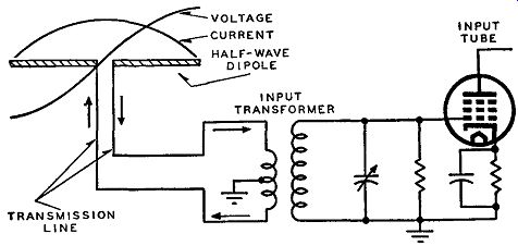
Fig. 6-12. Half-wave dipole and input circuit to the r-f amplifier.
The arrows indicate the current flow, which being a maximum in the trans
former primary, induces a maximum voltage in the secondary at the frequency
of operation.
It is well known that a maximum voltage input to the receiver is desired, but the feed-in to the simple half-wave dipole antenna or folded dipole is center driven and at this point the current is effectively at a maximum. How, then, can we conceive of a maximum voltage to the first FM tube? There are numerous ways of explaining this, one of which follows: In Fig. 6-12 a dipole antenna and input circuit to an FM receiver is illustrated along with the current and voltage curves effective at the dipole. Since the center point of the antenna is at the loop of the current curve, a maximum amount of current will flow through the primary of the input transformer. This maximum amount of current sets up a maximum magnetic field which causes a maximum voltage across the secondary due to induction. Since the parallel tuned secondary circuit is resonant at the frequency of operation, maximum voltage is developed at this desired frequency, which is applied to the grid of the input tube.
Noise Reduction
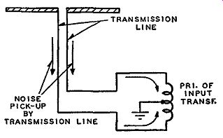
Fig. 6-13. In order to re duce noise pickup through the medium of the
transmission line, the center of the primary winding of the r-f transformer
is grounded.
This increases the signal to-noise ratio at the input of the receiver.
In many FM antenna systems, the primary of the input transformer has its center point grounded to reduce noise interference through the medium of the transmission line. This was illustrated in Fig. 6-12, but the left-hand side of this figure is redrawn in Fig. 6-13, to make this system of noise reduction somewhat clearer. Since the transmission line used may cover a greater area than the antenna itself, it has a tendency to pick up noise voltages, especially if the transmission line is quite long. To reduce this noise pickup and, hence, increase the signal-to-noise ratio at the input to the FM receiver, the center tap of the primary is grounded. It reduces noise pickup in the following manner:
The noise signal, when it hits the transmission line, induces equal voltages in each lead of the transmission line which in turn produces noise currents that flow in the same direction in the transmission line as indicated in Fig. 6-13. By center tapping the primary of the input transformer to ground, this circuit becomes symmetrical, and the noise currents both flow toward this ground connection. This effectively makes the individual currents out of phase, and, since they are equal in magnitude, they produce magnetic fields which cancel each other and, hence, the total noise voltage induced in the secondary of the input transformer is virtually zero.
This reduction in noise pickup is only in reference to that picked up by the transmission line and not that noise picked up by the dipole itself. This latter noise, as well as the desired signal input, finds its way into the receiver, but this noise is small and, if it just changes the amplitude of the received signal, the FM receiver will take care of these amplitude variations in the FM signal by either limiting these variations or not responding to them at all.
Other FM Receiving Antennas
So far in the analysis of FM receiving antennas, we have dealt primarily with simple and folded dipole antennas with and without reflectors, because they are the types that are most universally used.
There are, however, numerous other types of antennas used for the reception of FM signals. Since these different types are quite numerous, we are going to analyze only two of these other FM antennas.
The two types chosen are unique in the field of FM receiver antenna design, as the idea behind their development is supposedly to achieve better signal pickup than is obtained with the types so far discussed.
The design principles and theory involved have already been discussed in general form as applicable to all antennas.
We have to understand a few facts about the economics involved in the design of FM antennas. Usually, if more time and equipment is put into the design of an FM antenna, the price will be high compared with other antennas. In other words, the radio set buyer, or even the radio manufacturer buying FM antennas, is often faced with limitations on how much he can economically afford to spend on FM antennas. Therefore, most antenna manufacturing companies refer to the electrical advantages or superiority of their product in respect to their price. They are trying to be as fair as possible to the public in establishing what they believe to be an honest account for what they have put into the antenna in the form of engineering design as well as material things. Thus the FM antenna field contains numerous manufacturers of the same type of antenna with approximately the same price and electrical specifications.
As in all fields, the trend in FM antenna design is to surpass in electrical performance what is already in the field. With this purpose there have been numerous types of FM antennas on the market, some of them of different design to be used in specially located areas with respect to the transmitter and others that are intended for over-all betterment of performance. The two antennas chosen here are unique in design and new in the field. According to specifications laid down by the manufacturers, the relative performance of these antennas can be checked against those previously discussed, and conclusions can be simply drawn for comparison purposes.
Dipole With a Director
In a previous section of this Section we analyzed the effects of using a half-wave antenna with a reflector, and indicated how the signal pickup by the antenna was increased due to this reflector unit.
These types of antennas are more or less fixed in position once the established point of assembly is chosen. It is, therefore, very cumbersome to vary the position of the antenna to increase the pickup of certain signals which are weak in strength.
To accomplish the effects of increase in gain similar to that allowed by the reflector and, also, have the position of the antenna elements variable without appreciably affecting the input impedance to the antenna, a unique design is used. Shur-Antenna-Mount, Inc., incorporates in an antenna design called the "Interceptor" the use of a director instead of a reflector in conjunction with a simple dipole element, to accomplish these afore-mentioned favorable conditions. A director is a term given to an antenna parasitic element that is oriented in the direction of the signal to be received.
If the spacing between a two-element antenna ( dipole with reflector or dipole with director) can be varied, we have a ready means of somewhat changing the position of the antenna elements to afford the best possible signal pickup. In this manner the degree of directivity can be adjusted to give the best reception from the various FM transmitters within range. However, in order to maintain the impedance match to the transmission line, the reflected impedance, and hence the total input impedance, should be kept as constant as possible. The usual spacing between the elements of a dipole with a reflector is about one quarter wavelength of the center frequency to which the dipole is cut. According to this approximate spacing, the input impedance is equal to approximately 75 ohms. Assume for the moment that the spacing is 0.2 of a wavelength long at 99 mhz and that the input impedance measured is equal to about 40 ohms. If the spacing is varied to one-quarter wavelength, the input impedance will vary and may be increased by 20 ohms, or more, and, consequently, the impedance match originally established at 40 ohms will not be maintained. Even though the actual field strength pickup by the dipole element may not change, the mismatch will cause a loss in the line, and less input will be effective at the receiver.
------------
2. A parasitic antenna element is one that ha& no transmission line attached to it and that provides for added directional characteristics to the so-called driven element.
---------------
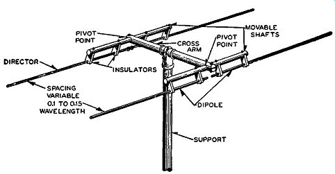
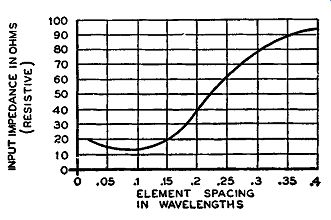
Fig. 6-14, above, Fig. 6-15, below. How the director is installed in
an array with respect to the dipole is shown in Fig. 6-14. The curve
below shows how the input resistive impedance varies with element spacing
in wavelength.
The use of a director placed a certain distance away from the dipole affords approximately the same field strength pickup by the dipole when it is varied by 0.05 of a wavelength as the use of a reflector.
It also keeps the input impedance of the system practically constant.
To be more exact, the antenna system under discussion, as illustrated in Fig. 6-14, can have its spacing varied between 0.1 and 0.15 wavelength, and yet the input impedance will remain substantially constant. The curve of Fig. 6-15 shows how the input impedance (which is resistive) varies with respect to wavelength. At 0.1 of a wavelength the input impedance is seen to be equal to about 14 ohms, and at 0.15 wavelength the impedance is only about 20 ohms.
This means that in this range of spacing the input impedance changes by only about 6 ohms. With the transmission line used, it is matched to the 14 ohms at its minimum spacing. However, if the spacing is varied by moving the elements over or under the crossarm (see Fig. 6-14), the input impedance will change slightly, being at the most about 6 ohms higher at the maximum spacing allowable. This means that the impedance match originally made changes very little, so that the slight mismatch that does occur will cause only a minute loss. Therefore, the elements can be varied either over or under the cross arm, so that the pattern of reception can be altered.
We have mentioned that the transmission line used with this antenna is supposed to match an input impedance of about 14 ohms, but as yet we do not know how this match is brought about with respect to the type of line used and the input impedance of the FM receiver. We intend to show this now. The impedance match to be discussed is based on a 300-ohm input impedance for FM receivers.
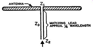
Fig. 6-16. A matching lead supplying an impedance Z3 that matches the
antenna or source impedance Z 1 to the load impedance Z1.
Since the transmission lines available do not have a characteristic impedance as low as 14 ohms, a special matching section between the antenna and transmission line is needed. Transformers of the proper design can accomplish this very well, but they are an expensive item.
In general, transmission lines, if cut to certain lengths at the frequency of operation, can act as transformers and be used successfully as well as economically for matching purposes. To determine the type of transmission line to be used as the matching lead, two things must be known; the impedance of the antenna and the characteristic impedance of the transmission line that is being used with the receiver. A piece of transmission line approximately a quarter wavelength long at the frequency of operation, provides a quick method of impedance matching. For instance, in Fig. 6-16 a matching lead (about a quarter wavelength) having a characteristic impedance equal to Z3 is being used to match the antenna impedance (or source impedance) of Z1 to the load impedance z,. The impedance seen looking into the matching lead is equal to z,. and by simple mathematics the impedance of the matching lead is given by the following: Z8 = \I (Z1 ) X (Z,) If the antenna impedance is 14 ohms and if 300-ohm transmission line is to be used to match the receiver input (usually 300 ohms), we can compute Z3.
Thus: Z8 = y (14) X (300) = y4200 64.8 ohms
--------------
The figure 0.69 is obtained from the manufacturer's data and takes into account the velocity of propagation in the matching section.
----------------
From this result, we find that the impedance of the matching unit should be 64.8 ohms. Transmission line of this impedance is not commercially supplied, and the one nearest to it has to be used, which means that a 75-ohm transmission would have to be used for this match. As a result of this slight discrepancy, the length of the matching section instead of being an ideal one quarter wavelength long is somewhat shorter. For the "interceptor" antenna discussed here, the frequency to which the antenna is cut is equal to 98.75 mhz, and one quarter of a wavelength at this frequency would be 2952/f (mhz) electrical inches long. However, this value is multiplied by 0.69 to obtain the physical length of the 75-ohm matching section. Thus: 2952 . L = 98 _ 75 X 0.69 = 20.63 inches and the length of the 75-ohm matching section is 20.63 inches (or 20o/s inches) long.
It should be remembered that a parasitic element, when used as a director, should be oriented toward the desired signal to be received.
Omnidirectional FM Antenna
All the antennas discussed so far were either unidirectional or bi directional. That is, the antenna could receive signals in only one or two directions. The simple dipole or folded dipole antenna is bi-directional because it can receive signals from two directions. The dipole antennas with reflectors receive signals from one direction only, be cause signals on the reflector side of the arrangement are prevented by the reflector from being picked up by the dipole element.
Other types of FM receiving antenna arrangements make use of signals from all directions; such antennas are called omnidirectional.
It is readily conceivable that an antenna arrangement that makes use of signals from all directions will respond to more signals than antennas that are directional in character. One of the most important advantages of such an antenna is that it does not have to be oriented in any one direction since it can receive signals from all directions.
One such antenna, manufactured by the Wind Turbine Company of West Chester, Pa., appears to be simply one bay of the turnstile antenna used for FM transmission. This FM receiving antenna makes use of the Brown developed coaxial radiator as used in the original turnstile antenna, resulting in a good impedance match to the trans mission line over a broad band of frequencies. By the use of coaxial radiators for the antenna elements the impedance of the over-all antenna can be adjusted through a varying range of resistive values, so that impedance matching to the necessary transmission line can be attained. It should be remembered that in the analysis to follow the characteristics of this antenna are the same when used for the transmission of FM signals as well as for their reception.
Fig. 6-17. A cross-sectional view of a typical coaxial radiator. By varying the radiating element of length A along the length of the coaxial tuner any reactance of the radiating element can be tuned out by the reactance of the opposite sign of the coaxial tuner.
SHORT CIRCUITED COAXIAL TUNER
A cross section of a typical coaxial radiator is shown in Fig. 6-17.
It essentially consists of a hollow radiating element of length A into which is inserted a short-circuited coaxial tuner of effective length B. By varying the radiating element along the length of the coaxial tuner any reactance of the radiating element can be tuned out by the reactance of the opposite sign of the coaxial tuner of length B. Two of the radiators shown in Fig. 6-17 form a dipole element with the input impedance of the dipole a pure resistance due to the canceling of the reactances of the radiating element and the tuner. A cross sectional view of such a dipole element is shown in Fig. 6-18 with the coaxial tuner common to both radiator elements. Each radiator element has a separate coaxial transmission line feed point.
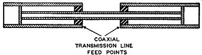
Fig. 6-18. Dipole element consisting of two coaxial radiators with the
coaxial tuner common to both elements.
When omnidirectional characteristics are desired in the horizontal plane, as is the case for FM signals, two such dipole arrangements are placed at right angles to each other. That is, both dipoles have their center coaxial tuning elements perpendicular to each other. Due to the arrangement of the antenna system the voltage received by one dipole element is 90° out of phase with the other. Since the dipole elements are at right angles to each other it is common terminology to call one the east-west dipole and the other the north-south dipole.
In the usual turnstile element the 90° phase difference is obtained by coupling both dipoles together through a transmission line an odd multiple of a quarter wavelength long, in which case the line acts as a transformer. Under these conditions, at resonance the impedance of the radiator is made equal to the characteristic impedance of the transmission line used for coupling. This is shown in Fig. 6-19 where the N-S and E-W antenna elements each is represented by an impedance equal to Z 0, which is the characteristic impedance of the transmission line shown coupling both dipole elements. Therefore, at point C in the schematic of Fig. 6-19 the impedance offered by both the north-south (N-S) and east-west (E-W) dipoles is equal to Z0. Since both dipole elements represent the same impedance at point C, the impedance seen looking into the transmission feed line is equal to Z0/2. With such a turnstile arrangement for the transmission of FM signals at one frequency, the antenna operates satisfactorily and is broad so far as the impedance is concerned. This broad impedance effect holds even if the dipoles become slightly off tune. However, the radiation pattern for the antenna will change, and this is not desirable for maximum signal input to the FM receiver using such an arrangement.
When the dipoles are off tune, the impedance will increase since it is a minimum at resonance. This increase may be slight enough not to affect the broad-band impedance effect, but it will affect the radiation pattern. The new off-tune impedance for each element will be Z 0 + Z1,
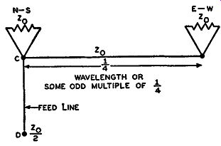
Fig. 6-19. Schematic representation of an omnidirectional antenna, where
Z0 is the characteristic impedance of the transmission line and is also
the impedance of the two antenna elements.
where Z1 is the slight increase in impedance. At the input of the quarter wavelength coupling line the new impedance presented by the east-west dipole will be equal to (Z0 )2/(Z0 + Z1 ), which means that the currents delivered by each dipole to the feed line will be different.
Consequently, the effective horizontal radiating pattern of the whole antenna will no longer be properly circular, but, when the antenna is badly detuned, will deteriorate to the familiar figure-eight pattern of a simple dipole. Thus, being slightly off tune will change the radiation pattern of the antenna somewhat, which means that the antenna is not broad band to this desired pattern.
To make this antenna system broad band to the radiation pattern as well as to the impedance, a slight change in the transmission line arrangements is made. Instead of the north-south dipoles being fed directly through the transmission feed line and the east-west dipoles through the quarter wavelength coupling line, both are fed in a slightly different manner from that shown in Fig. 6-19. This new arrangement, as used in the turnstile FM receiving antenna of the Wind Turbine Company, is illustrated in Fig. 6-20. The north-south dipole element is fed through a transmission line equal to some length designated by the letter L and the east-west dipole is fed through a line equal to L plus the one quarter wavelength ( or some odd multiple) of the coupling line. This differs from the former arrangement in that lines of length L are added to each dipole feed and then coupled together.
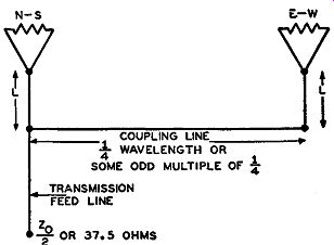
Fig. 6-20. Schematic representation of an omnidirectional antenna that
is corrected for off-tune conditions. The additions of the transmission
lines of lengths L makes the system broadband to the desired radiation
pattern and impedance.
Compare Figs. 6-19 and 6-20. The phase difference between these two dipoles is not altered by this new arrangement and still remains at 90°. The north-south dipole is fed through an effective transmission line transformer network of length L and the east-west dipole through a transformer of length L + n,\/4 (where n stands for any odd multiple of one-quarter wavelength line and ,\ denotes the wavelength of the frequency in question). Off tune the impedance presented by each dipole will change as it did for the former arrangement. The mathematical expressions for the impedances at the input to each feed line are too complex to show here. Suffice it to say that the length of L can be chosen according to the characteristic impedances and frequencies involved, so that the magnitude of the impedances offered by both dipoles at the input to their feed lines are the same at some frequency. The resistive and reactive components of the dipole impedance are equal in magnitude, but the reactive components are opposite in sign. In other words, when one impedance offers a reactive component that is inductive, the other offers a reactive component that is capacitive. This is due to the maintenance of the 90° phase difference between the dipoles. The parallel impedance of these two dipole impedances is, then, purely resistive, and equal induced currents will flow in each dipole maintaining the required circular radiation pattern. There is a slight phase difference between the currents, but the phase angle of current in each dipole is very low, so that the phase difference between the two currents is low and has negligible effect on the proper operating of the system.
The antenna system is so designed that the frequency at which the compensating lines of length L perform their function is near one end of the FM band, while the dipoles are in tune near the other end.
Thus, the radiation pattern is given a broad-band effect, so that the antenna is omnidirectional throughout the FM band.
The dipole element formed by the two coaxial radiators has an input impedance equal to 300 ohms at the two points of feed-in seen in Fig. 6-18. To convert the high impedance of this balanced output to the low impedance of the unbalanced coaxial transmission line, a special transmission line network is employed. This is illustrated in Fig. 6-21.
A half-wave length of coaxial transmission line with a characteristic impedance equal to one-fourth the impedance of the balanced output is bent in a U shape, as shown in Fig. 6-21. The impedance between the center conductor and outside conductor (or ground) of the bent coaxial line, is equal to 75 ohms. If a 75-ohm coaxial transmission line is attached to the center conductor at either end of the half-wave coaxial line, the impedance seen, looking into this newly attached coaxial line, is equal to 75 ohms.
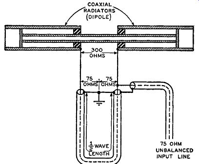
Fig. 6-21. High-frequency network that is used to convert the high impedance
of a balanced output to the low impedance of an unbalanced coaxial line.
This system is incorporated in the complete FM receiving turn stile antenna arrangement shown in the diagrammatic drawing of Fig. 6-22. Each dipole element has a balanced impedance equal to 300 ohms which is transformed to 75 ohms unbalanced by the half wavelength 75-ohm U-shaped coaxial line. Thus at point D the impedance seen is equal to 75/2 or 37.5 ohms. By use of a quarter wave length piece of 50-ohm coaxial matching line this 37.5-ohm impedance at point D is transformed to 75 ohms again. This 50-ohm matching section functions in the manner described under the discussion of the dipole and director arrangement. Since the receiver is based on a 300-ohm impedance, a similar U-shaped one-half wavelength of 75 ohm coaxial transmission line, as used for the dipole elements, is used to convert the unbalanced 75 ohms of the transmission line to the balanced 300-ohm impedance of the receiver for the final impedance matching for the complete system.
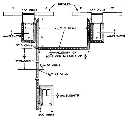
Fig. 6-22. Network that is used in the omnidirectional antenna under
discussion to couple the 300-ohm antenna to a 300-ohm input impedance
receiver through a 75-ohm transmission line.
One advantage of the coaxial transmission line over the twin-lead transmission line is that the coaxial line has low loss and inherent low noise pickup. The system of Fig. 6-22 may appear complex in arrangement compared with the others, but it actually is not, since the complexity of the drawing is due to the coaxial lines which occupy little space compared with the dipole elements. Since this antenna offers omnidirectional characteristics, under the conditions of broad-band effects for both impedance and radiation pattern, it will result in better performance for general use than most directional antenna arrangements.
Notes on Installation
It is beyond the scope of this guide to discuss the installation procedures for all the different FM antennas manufactured. The following notes, however, cover the installation of outdoor FM receiving antennas and apply to all types, unless otherwise specified.
One of the primary requisites in all installations is that the antenna system be mechanically secure. The first necessity is to make sure that high winds, rain, ice, or snow will not affect the mechanical secure-ness of the system. The reason for this is obvious, since it is desirable that the antenna require little attention once it is installed.
Most types of antennas are supplied with the necessary mechanical supports to attach the system to some object such as a roof, chimney, or side of a house.
The antenna should be placed as high as possible and away from any interfering objects which might reflect the FM signals. Consequently, such high installation points as roof tops are used. The antenna also should be mounted some distance away from any of the metallic objects commonly found on a roof top, such as water drains, pipes, and wires. It is quite as important to make sure that the trans mission line used (especially if it is the twin-lead type) is also kept away from metallic objects. By placing the transmission line near such objects, noise and other types of undesired reflected signals can be picked up by the line.
Once the spot with the most freedom from metallic objects has been chosen, two remaining important factors must be taken in to account: the orientation of the antenna proper and the correct installation of the transmission line from the antenna to the receiver. In using antennas that are unidirectional or bidirectional, it is important to know something about the FM transmitting stations within the coverage area of the receiver in question. If the field intensities of most of the transmitting stations within the vicinity of the receiver are about the same, not much difficulty will be encountered in orienting the antenna. If most of these stations are quite near each other as far as the receiver is concerned, the receiving antenna can be oriented simply by placing the pickup element broadside to the oncoming FM signals. If the antenna is placed in a different position there may be a noticeable loss in signal pickup when the receiver is in operation.
This is particularly true when the receiver is quite a distance from the FM stations. However, as pointed out, in localities where the receiver is in the vicinity of strong local stations, variation in the position of the antenna may make little difference.
If the strengths of the FM transmitted signals, in the locality of the receiver in question, are quite different and if they approach the receiver from different directions, it is advisable to orient the antenna broadside to the signals that are weakest, in order to have adequate signal pickup on most stations.
The field pattern for a dipole, considered either in the receiving or transmitting sense, is the conventional figure-eight pattern, as shown in Section 5, with the points of maximum and minimum signal pickup 90° out of phase with each other. Therefore, when going from a minimum signal pickup to a maximum the antenna should be rotated by 90°. The installation of the transmission line is as important an item as the antenna itself. The transmission lines most commonly used are of two types: the open-wire twin-lead line (with plastic insulation) and the common coaxial line. Both types can be supplied with different characteristic impedances. It is usual, however, to use the twin-lead type of 300-ohm characteristic impedance, since most FM receivers have an input impedance of 300 ohms. The coaxial type transmission line does not run into such high impedances, usual values being 50, 75, and 150 ohms. However, each individual antenna arrangement re quires its own specific setup. The importance of correct impedance matching for maximum energy transfer should be remembered, especially in localities where the received signals are weak. One advantage of the coaxial line is that it has low noise pickup, as compared with the twin-lead type. However, the quicker and easier impedance matching for the twin-lead type sometimes makes this kind more suitable than the coaxial type.
No matter which type is used, the slight difficulties may be over come by careful installation. In attaching either type line from the antenna to the receiver, the length of line used should be as short and as rigid as possible. The requirement for a short line arises from the fact that the longer the line, the more signal will be lost. The rigidity requirement is necessary to prevent the line from swaying with the wind. A number of things may happen if the line does sway in the wind. The line may be moved near some metallic object, it may be scraped constantly against something which will make for quick deteriorating of the insulator and then perhaps shorting of the line elements, or the line may even be snapped by a strong wind.
The mast and supports of the antenna should have some provision for stand-off insulators or guide loops, so that the portion of the trans mission line leading from the antenna can use these insulators or guide loops as a means of preliminary support. These special attachments help maintain rigidity in the line and prevent any unnecessary swaying. Some manufacturers suggest that, when passing twin-lead line through these loops that are connected to metal masts, the line should be twisted two or three times to maintain electrical balance between each wire of the line and the metal mast and thus minimize noise pickup. However, these twists in the line should be made only in the vicinity of the metal mast.
After passing through the insulators or guide loops, the line should be drawn tight until it is attached to the receiver. In doing this, the line may be pressed flat against only those types of objects that will not influence its transmission characteristics. Such things as wood, brick, and roof shingles (no metal involved) are commonly used. To secure this tightness in the line, special guide loops or other such attachments are often attached to some place in the vicinity where the transmission line is running. Twin-lead line may be fastened at a number of points by using small metal brads (that is, nails without any heads) through the center of the plastic insulator and into any material that will take the nail, and also provided it is not metallic.
The brads themselves have a negligible effect on the transmission of the signal along the line, but if nails with heads or similar things are used, difficulties may arise. A wearing effect on the insulator may occur and the line may be short-circuited, or the characteristic impedance of the line at the point where the nails pass through it may be changed, causing a mismatch from the antenna to the receiver.
QUESTIONS
SECTION 6
6-1. When we speak of the noise content of an FM signal at the detector circuit of an FM receiver, this total noise originates from two main sources-what are they?
6-2, a. Discuss the voltage and current distribution along a full-wavelength antenna with regard to the points of maximum and minimum voltage and current. b. Repeat part (a) with respect to a half-wave antenna.
6-3. Why are the dipole antennas, such as those illustrated in Fig. 6-3, termed current-fed antennas?
6-4. a. What are the names given to the two resistances of an antenna? b. Which resistance is usually the higher and what is the approximate value of this higher resistance for a simple dipole antenna in free space?
6-5. Discuss the reason why at its feed-in points, a center fed simple dipole antenna behaves like a series resonant circuit at the frequency to which it is cut.
6-6. In an FM receiving system would impedance-matching the transmission-line to the antenna only, assure the maximum amount of energy transfer from the antenna to the receiver?
6-7. How does the input impedance of a simple dipole change at frequencies on either side of that to which the half-wave antenna is cut? Does this changing impedance remain purely resistive?
6-8. a. Explain how the Q of a dipole is decreased when the diameter of the dipole is increased.
b. A reduction in the Q of a dipole enables the dipole to have a broad band response. However, there is a limitation to the amount of reduction of Q and hence, a limitation in how broad-band the antenna can be. Why is this so?
6-9. Under ideal conditions, if the input impedance of a simple dipole is assumed to be equal to 100 ohms, then based on this assumption what is the input impedance of a folded dipole?
6-10. Why does horizontal polarization, as used in FM broadcasting, provide for a better signal-to-noise ratio at the input to the FM receiver than vertical polarization?
6-11. In what position should the FM receiving antenna be placed and in what direction should it be oriented for maximum signal pickup?
6-12. What does a reflector element used with a dipole do for the antenna system?
6-13. a. Under ideal conditions (free space) what would be the length of a half-wave antenna for the center of the 88-to-108 -mhz band? Give your answer to the nearest whole number. b. If the weakest FM signal in an area is at a frequency of 91 mhz, to what length would a receiving dipole be cut under normal conditions?
6-14. A balanced input receiver is one that has the center tap of its input coil grounded. This is supposed to help eliminate noise pickup by the transmission line. Explain how this is brought about.
6-15, a. Is a director or reflector element usually oriented broadside to the oncoming signal? b. If the input impedance of an antenna system equals 18 ohms, and if a 150-ohm transmission line is used with a 150-ohm input FM receiver, what is the calculated characteristic impedance of a quarter-wavelength piece of transmission line used for correct matching between the antenna and the 150-ohm line? c. It was found that for a certain FM antenna system employing a number of parasitic elements the input impedance was 75 ohms.
It was also found that a piece of 150-ohm transmission line of the proper length was needed as a special matching section to match the antenna to the load. What must the load impedance be to require such a match?
6-16. What type of FM antenna will receive signals from all directions?
6-17. What are three important requisites for the installation of the f-m antenna system?