In the preceding Section we discussed many different FM transmitters of both wide-band and narrow-band characteristics. The different discussions centered about the exciter unit which essentially consisted of the oscillator-modulator stages, the frequency multiplication system, and the center frequency control system (if the type of modulation was direct FM). The power stages of the different transmitters were not included because the operation of those stages are similar to the power stages in a-m transmitters except for a few details. One of the differences between the power stages as used in a-m and FM transmitters (especially on the broadcast band) is the frequency involved and the type of modulation. The circuit components and power tubes used in FM are chosen to give the proper frequency response characteristics over that portion of the FM band where they are operative. Another very important difference is the wide bandwidth used in FM as compared with the normal maximum of 15 khz used in AM The tuned circuits in the FM transmitters have to be broad enough to handle the band widths in FM. If it were not for these differences, there would be very little difference between the design of a-m and FM power stages operating on the same power level. However, these differences do exist, and, consequently, they alter the design of the antenna systems for FM as compared with AM.
In FM broadcasting, the range of transmitted frequencies is around 100 mhz and in a-m broadcasting around 1 mhz. Due to this great difference in frequency, the propagation of FM signals is much different from that of a-m signals. There is a limitation to the area that an FM signal can cover compared with the coverage area of a-m broadcast signals. You will notice that so far we have made reference only to the differences between broadcasting FM and a-m stations. The reason for this is deliberate, because so far as narrow-band FM and amateur AM are concerned, there is very little difference in the nature of the propagated signals. The frequencies involved in narrow band FM and amateur AM are very close, so not much difference exists in the manner in which they are propagated through space.
This Section will discuss the transmission of FM signals from the output of the final power amplifier stages to the FM receiver relative to the broadcast band. In this respect different types of FM antennas will be analyzed in conjunction with their radiating pat terns. After the FM signal leaves the antenna in its special direction (due to its predetermined radiated pattern) it will travel through space differently from a-m broadcast signals and, consequently, the different layers of the atmosphere and also the nature of the terrain play an important part in FM signal propagation. This will be seen later in this Section. The last part of this Section will deal with the service or coverage area of an f'-m signal and also interference effects.
Its relative merits and defects will be compared to a-m signals of the broadcast band.
THE TRANSMITTING ANTENNA
The final stage of all transmitting systems is the antenna. In almost all stations the antenna is connected to the final power amplifier stages through some transmission line system. Antennas always play a very important role because they are the final stepping stone in preparing the FM signal for its propagation through space as an electromagnetic signal. Their designs are equally, if not more, critical than other stages in the transmitters. The purpose of this section is to acquaint the reader with some of the transmitting antennas used in commercial broadcasting stations. The reason for this is that these transmitting antennas are more complicated in design than those used on narrow-band FM, such as ham and police transmitters.
When considering FM transmitting antennas, it should be remembered that we have to deal with frequencies well up in the very high frequency region. (The old band FM was around 50 mhz and the new band is around 100 mhz.) Consequently, propagation in FM is different from that of AM, which means that the coverage or service area for FM is also different.
One of the most important considerations is that the antenna and its associated coupling network be so designed that it will not cause any phase distortion in the transmitted signal. In a-m transmission the introduction of phase distortion will not be detected by the receiver, but in FM transmission it will. Phase distortion causes an equivalent frequency change, which means that the FM signal effectively becomes distorted in frequency, Since the FM receiver is so designed that it corresponds to frequency variations of the trans mitted signal, the distortion will become apparent. Of course, amplitude distortion is also undesired, but the FM receiver can take care of moderate changes in amplitude by its limiter action or by special detection methods.
To minimize the effects of phase or amplitude distortions that might be introduced in the FM signal by the coupling from the final power amplifier stage to the antenna, the input impedance should be broad over the complete peak-to-peak frequency deviation range. This means that, since the maximum peak-to-peak frequency deviation is equal to 150 khz, the input frequency response characteristic of the antenna has to be at least broad enough to accept a 150-khz band width, or 75 khz on either side of the carrier frequency of trans mission. It should be somewhat broader, because the significant side bands at peak deviation may extend as far as 100 khz either side of the carrier.
The type of antenna that is employed depends upon the service area to be covered, the position of the antenna within the required service area, and the height of the antenna above the terrain. Where the communication is between two fixed points, a radiated signal in the form of a narrow beam is the most desirable type, because, if the signal were radiated in any direction other than toward the receiver, there would be no receiving antenna to pick up the signal and that energy would be lost. In commercial broadcasting the situation is completely different. The antenna must be designed to radiate out ward in all directions, in order to cover the necessary service area where any number of FM receivers are located.
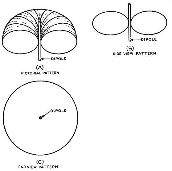
Fig. 5-1. The pattern of the electromagnetic radiation from a di pole
antenna is shown pictorially m (A). A cross section of the pat tern from
the side of the dipole is shown in (B) and its appearance when viewed
from an end of the dipole is shown in (C). These views of the radiation
pattern are drawn for a vertical dipole.
Due to the nature of the atmosphere and the frequencies involved, the FM signal radiated from the antenna has to be in a horizontal direction to cover the necessary area with the greatest amount of field intensity. The radiated signal from the antenna is an electromagnetic wave which is alternating at a certain frequency, namely, the frequency of transmission. A half-wave dipole antenna has a certain radiating pattern in both the horizontal and vertical plane.
This is best illustrated in Fig. 5-1 which shows the field pattern for a half-wave dipole. The complete field pattern may be shown as a certain volume as in the pictorial cutaway pattern of Fig. 5-1 (A). The shape of the field is in the form of a doughnut. If the dipole were in a horizontal position and we looked straight down on it, we would observe the pattern in the form of a figure eight as shown in Fig. 5-1 (B). With the dipole in a vertical position and looking down on it, we would see a circular pattern as indicated in Fig. 5-1 (C). From the pictorial view of Fig. 5-1 (A) the side view and end view pat terns of (B) and ( C) are readily distinguishable. It is possible to have a signal radiated in a horizontal plane which is either vertical or horizontally polarized. The difference between the direction of propagation and polarization is often misunderstood.
It has been stated that the radiated signal is an electromagnetic signal which means there are two alternating fields involved, the electric field and the magnetic field. These fields are 90° out of phase with each other. When we talk of polarization, only the electric field is being referred to. This means that, according to the position of the antenna, the signal can either be horizontally or vertically polarized.
When the dipole is horizontal, the electric field is alternating in a lateral motion such that the signal is horizontally polarized; and, when the dipole is in the vertical plane, the electric field is alternating in an up and down motion such that the radiated signal is vertically polarized. The use of horizontal polarization for FM broad casting antennas has been standardized by the FCC, although exceptions may be made.
Generally, FM broadcasting stations are located approximately in the center of their service areas, so that the horizontal radiation pat tern has to be somewhat circular in shape in order to cover the necessary area. This means that the horizontal pattern must be circular in form and, because of the FCC requirements, horizontally polarized. This is accomplished by a number of different methods in which antenna arrangements using more than one half-wave dipole produce, as nearly as possible, a circular horizontal radiation pattern.
The more common FM broadcasting antennas in use today that have a circular horizontal radiated pattern (horizontally polarized) are the turnstile antenna, the circular antenna, the Pylon antenna, and the square loop antennas. There are also many other types of FM antennas, such as the clover leaf and the rocket antenna. Some of the things which dictate the choice of one style of antenna over another are the impedance matching of the transmission lines to the radiating elements, the shape of the terrain to be covered, and the service or coverage area.
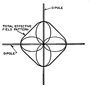
Fig. 5-2. A turnstile antenna consists of two horizontal half-wave dipoles
at right angles to each other. Compare the individual patterns here with
that of Fig. 5-1 (B). The total effective field assumes an approximate
rectangular pattern.
The turnstile antenna basically consists of two half-wave dipoles crossing each other perpendicularly at their mid-points, with the individual dipoles excited 90° out-of-phase with each other. Placed in a horizontal position, the horizontal field pattern for this antenna is that shown in Fig. 5-2, under the conditions that an equal amount of power is fed to each section. The circular antenna is simply a folded dipole bent in a circular shape, which gives a horizontal field pattern that is fairly circular. The Pylon antenna is a long piece of metal which is bent into a slotted cylinder where the complete cylinder itself is used for the radiation of the FM signal. The square loop antenna is just what the name implies, a square shaped loop, where the sides of the square are simple dipoles, folded dipoles, or the like.
The horizontal field pattern for these four types of antennas, or variations of them, is basically circular in shape.
Antenna Gain
In dealing with a single dipole or a single section (called a "bay") of a turnstile, circular, or square loop antenna, we are concerned with two patterns: the horizontal pattern and the vertical pattern. Since any signal radiated in the upward direction toward the sky layers is wasted, an antenna having substantial radiation in the vertical direction is wasteful and the effective radiated power from the antenna is small. In practically all FM broadcasting antennas a number of antenna elements or bays are used, stacked vertically a certain distance apart from each other to reduce the power radiated in the vertical direction and to concentrate or increase the power radiated in the horizontal direction. The larger the number of bays, the greater the concentration of power in the horizontal direction, but, in most cases, increasing the number of bays beyond a certain point decreases the effective concentration, so that a practical limit exists on the number of bays used.
When the power in the horizontal direction is effectively increased, the antenna is said to have a gain in that direction. Two separate gain factors are involved in antenna gain, namely, antenna field gain and antenna power gain. In this connection it should be stressed that the total power radiated from the antenna is never greater than the power input to the antenna. In fact, the best that can be achieved is that the input and output power be approximately equal, with the output power being slightly less due to transmission and feeder line losses.
Thus when we refer to one of the antenna gains we only mean a gain in the effective amount of radiated power as based upon a certain standard.
In other words when a single dipole antenna, horizontally polarized, is used, a certain signal voltage will appear at the input to a receiver antenna which is situated about 20 miles from the transmitting antenna. If the number of dipoles is increased in accordance with what was just discussed, the antenna radiation in the vertical direction will be reduced and increased in the horizontal direction. That is, the radiated signal from the vertical direction is pushed or forced into the horizontal direction. Under these circumstances, the receiver antenna 20 miles distant has an increase in the input signal voltage.
This clarifies how the reference to antenna gain is established. The antenna field gain or power gain is based upon measurements made with a vertical half-wave antenna as established by the FCC. If we replace the vertical half-wave antenna with any multielement FM antenna, there will be an increase in the field intensity in the horizontal direction. If this increase is expressed as a ratio, the antenna field gain can be calculated. Consequently, the antenna field gain is equal to the ratio of the field intensity measured with some multi element antenna to the field intensity with the vertical half-wave antenna. According to the FCC,1 these measurements are to be made at one mile from the antenna with a 1-kw input to the half-wave vertical antenna. At this one mile point, the field intensity measured for the half-wave antenna is equal to 137.6 millivolts per meter. This measurement is made under the conditions of free space field intensity, which means that the radiation signal existing at this one mile point is free of any reflections from the earth or other objects. There fore, the antenna field gain is equal to the following: Antenna field gain _ field intensity in mv /m for multielement antenna e - 137.6
The field intensity for the multielement antenna is also measured at one mile distant and at an input to the antenna of 1 kw.
The term power gain is used more often than field gain, and the former term is generally used to express the operation of the antenna.
The power gain is also based upon the use of a vertical half-wave antenna and it is only natural that there exists some relation be tween the field gain and power gain. The relationship is such that the value of the antenna power gain is equal to the antenna field gain squared. Thus, with F.G. meaning the antenna field gain and P.G. meaning the antenna power gain, the mathematical expression for their relation is:
P.G. = (F.G.)2 or F.G. = V P.G.
The true significance of the power gain of an antenna may not be immediately evident. But from the fact that the power gain of an FM antenna is based upon a standard half-wave antenna, it can be deduced that having a greater power gain requires less transmitter out put power to produce the same field intensity at some specific point.
In other words, if a 50-kw transmitter using a single half-wave dipole antenna produces a field intensity of, say 5000 microvolts, at some specific distance away from the transmitter, a similar FM transmitter operating on 10 kw, but using an FM antenna (in the same location) that has a power gain of 5, will produce the same field intensity at the same point.
[FM Broadcast Stations" of the FCC, antenna field gain for an FM broad cast antenna is defined as "the ratio of the effective free space field intensity produced at one mile in the horizontal plane expressed in millivolts per meter for 1-kw antenna input power to 137.6 mv /m." ]
From this simple analysis it can be seen that for a specified amount of effective radiated power in the desired directions we have two methods to choose from. We can use either a high powered transmitter with a simple antenna having unity power gain (or less) or a much lower powered transmitter with a much higher antenna power gain to accomplish the same thing. However, since it is less expensive to employ an FM antenna with high power gain than it is to increase the power output of the transmitter, practically all FM broadcasting stations use some form of multielement antenna that has a sufficient power gain to cover the necessary service area.
The Circular Antenna
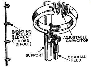
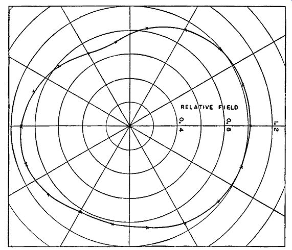
Figs. 5-3, left, 5-4, right, 5-5 below. A four-bay circular antenna,
one element of which is shown at the right. Below is shown the horizontal
field strength pattern taken at 107 mhz for the bottom bay of an 8-bay
antenna.
As mentioned previously, most types of circular antennas consist of a vertically stacked series of folded dipoles which are bent in the form of a circle. A typical circular antenna as used for FM broad-casting is illustrated in Fig. 5-3. The type shown is a four bay circular antenna of the General Electric Company. In Fig. 5-4 a single radiating element is illustrated. The adjustable capacitor on each folded dipole permits tuning each radiating element to resonance at the frequency of operation of the FM transmitter. The measured horizontal field strength pattern taken at 107 mhz for the bottom bay of an 8-bay antenna (located at the point of largest pole diameter) is shown in Fig. 5-5. It should be noted that the effect of the pole on the horizontal field pattern is quite small, and this effect will decrease as the pole size tapers toward the top. This slight directional effect can be used to advantage in certain installations.

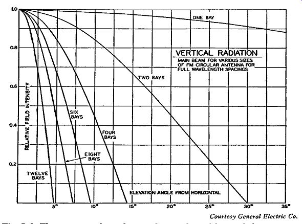
Fig. 5-6. These curves show that as the number of bays of the antenna
shown in Fig. 5-3 is increased, the vertical radiation pattern is decreased.
To show that, as the number of bays is increased, the vertical radiation pattern is decreased, a number of curves is drawn as illustrated in Fig. 5-6. These curves are a plot of the relative field intensity versus the elevation angle from the horizontal. They show that, as the number of bays is increased, the vertical pattern is constantly "squeezed" down to a point where, for 12 bays, it is about 5 degrees from the horizontal. This means that the vertical pattern is shaped in the form of two leaves about 180° out of phase with each other and that the angle of measurement is made along the line going through the center of these leaves. In this graph the bays are separated from each other by full wavelength spacings. It was found that for a 2-bay circular antenna of this sort the antenna power gain is 1.7; for a 4-bay antenna the power gain is 3.63; and for a 6-bay antenna the power gain is 5.50.
The Turnstile Antenna
The turnstile antenna, developed by G. H. Brown, was one of the very first types of antennas used for FM broadcasting. There are a number of variations of the turnstile antenna, but essentially all types produce a roughly circular horizontal pattern as shown in Fig. 5-2. The greater the number of turnstile elements, the greater will be the power gain, because the vertical field pattern is constantly reduced in power and the horizontal field increased.
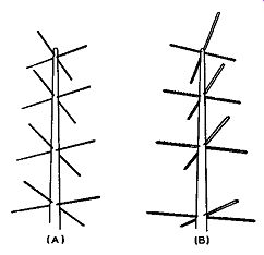
Fig. 5-7. Two types of turnstile antennas are illustrated at the left.
In (A) each of the four bays consists of two half wave dipoles and in
(B) each individual bay consists of two half-wave folded dipoles at right
angles to one another.
Fig. 5-7 illustrates two different types of turnstile antennas. In part (A), the turnstile antenna consists of 4 bays, where each bay itself contains two half-wave dipoles at right angles to each other.
In part (B), the turnstile antenna also consists of 4 bays, but the individual turnstile bays consist of 2 half-wave folded dipoles at right angles to each other. Some of the reasons why one kind of turnstile antenna is used rather than another are the spacing between bays and the impedance matching of the transmission lines to the radiating elements. These are typical problems which are too complex to analyze here. They exist in all types of broadcasting antenna systems and are not peculiar to the turnstile antenna.
In most types of multielement antennas (as those discussed in this guide) the spacing between the bays is some portion of the wave length of the frequency of operation. The actual value of spacing used differs for different antennas; but in general the spacing is so chosen that a portion of the vertical field pattern from each bay cancels some of the vertical pattern from an adjacent bay, in which case the field energy is increased in the horizontal direction. As the number of bays is increased, greater cancellation of the vertical component is obtained, and the larger the horizontal component becomes. Hence, the greater the power gain.
The Pylon Antenna
This antenna, which is of RCA design, is one of the latest to be added to the field of FM transmitting antennas. The Pylon antenna essentially consists of a long metal sheet which is rolled into a cylinder with a slotted section. A drawing of a two-section Pylon antenna is illustrated in Fig. 5-8 (A), and an enlarged cross sectional view in Fig. 5-8 (B). Power is fed to the slot of the antenna in which case this slot functions as a transmission line. This effectively means that the complete cylindrical surface of the antenna is used as a radiating element. This antenna can also be visualized as being made up of an infinite number of circular antennas, one stacked on top of the other, with each one serving as a radiating element.
The diameter of the antenna is a controlling factor in the shape of the horizontal radiation pattern and also the length of the antenna section so far as resonance at the desired frequency is concerned. The width of the slot of the antenna is the most important determining factor in the input impedance of the antenna.
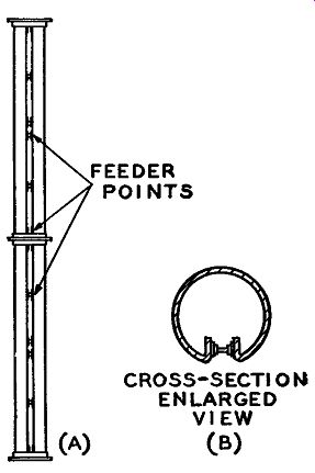
Fig. 5-8. The Pylon antenna consists of a long metal sheet rolled into
a cylinder with a slotted section, a cross sectional view of which is
shown in (B). When power is fed to any of the feeder points indicated
in (A), the slot functions as a transmission line.
The two section Pylon antenna at (A) increases the horizontal field pattern as well as the gain as compared to a single section.
As with the other antennas, placing one Pylon section over another increases the horizontal field pattern as well as the power gain.
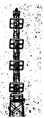
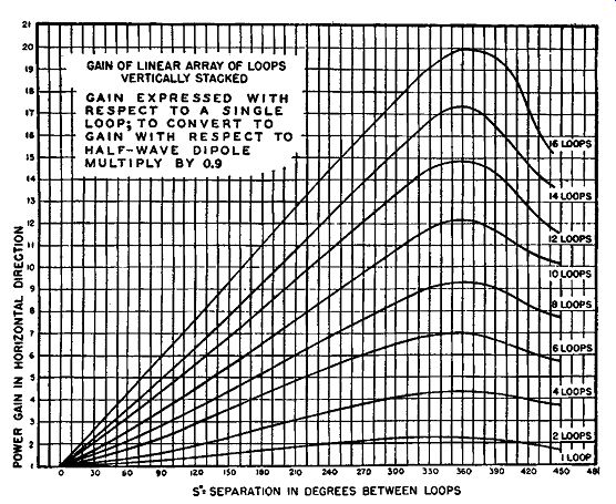
Fig. 5-9, left, Fig. 5-10, below. The square loops of the antenna shown
in (A) give a somewhat greater power gain than either the circular or
turnstile antennas from the standpoint of the number of bays used in
each type. Graph below indicates the number of degrees separation be
tween the loops plotted against the horizontal power gains for a different
number of loops. This shows that the greater the number of loops, the
greater is the power gain.
The Square Loop Antenna
Another variation of an FM broadcasting antenna is the square loop antenna. This type antenna is also supposed to give a somewhat circular horizontal pattern (and also to be horizontally polarized). The features relative to the increase in the number of bays, reduction in vertical power, and increase in horizontal power holds true for this type antenna as well as the others. The square loop antennas give a somewhat greater power gain than either the circular or turnstile antennas, from the standpoint of the number of bays used in each type. A pictorial view of the Federal Telephone and Radio square loop antenna is shown in Fig. 5-9. A 4-bay antenna is shown; the spacing between loops for this arrangement is about 330° of the wavelength at the center of the FM band (where 360 degrees is equivalent to one wavelength). Each side of this square loop is approximately one-half wavelength long.
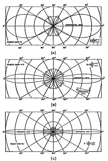
Fig. 5-11. Vertical radiation patterns for 2, 4, and 8 loops in (A),
(B), and (C), of the square-loop antenna show that as the number of loops
is increased, the vertical power radiated is decreased.
An idea of how the power gain of the antenna is affected by the separation between loops, as well as the number of bays, can be had from the graph of Fig. 5-10. This graph, according to computations made by Federal Telephone and Radio Corporation, shows the plot of degree separation between loops versus the horizontal power gains for a number of different square loop antennas. The graph makes it immediately obvious that increasing the number of loops increases the power gain. It is also seen that approximately 1 wavelength separation (360 degrees) between loops give the maximum power gain for practically all loop combinations. The gain increases in the horizontal direction as the number of loops, because the power in the vertical direction is decreased. In Fig. 5-11 are illustrated three vertical radiation patterns for different loop combinations of 2, 4, and 8 loops. The power gain and separation between the loop elements are indicated with the drawings. Check these power ratings with the graph of Fig. 5-10, and it will be seen that they are correct. From these vertical patterns, as determined by Federal Telephone and Radio Corporation, it is seen how the strength of the main vertical loops is decreased as the number of bays is increased. This means more power for the horizontal field pattern and, hence, a greater power gain for the antenna.
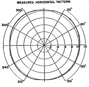
Fig. 5-12. The measured horizontal radiation pattern of the square-loop
antenna array is circular, which if it were calculated mathematically,
would be approximately a square, as this method does not take into account
the end effects of the half-wave elements of each square loop.
If the horizontal radiation pattern were calculated by mathematics, the pattern would be somewhat in the shape of a square, because the calculations would be done without taking into account the end effects of the half-wave elements of each square loop. (This end effect has some special significance in the voltage and current distribution.) The horizontal radiation pattern, taking these end effects into account, would be the result of a measured pattern. This measured pattern is shown in Fig. 5-12, where it is seen that the true pattern is quite circular in shape, which is a desirable characteristic.
Other Antenna Considerations
From the standpoint of power gain, one of the most important things determining the type of antenna used, is the situation of the antenna and its height above the average terrain. The FM antenna should be located as high as possible because the radiated waves are then directed that much farther away from the ground, and, consequently, there is less chance of reflected ground waves. By this method, and by the horizontal pattern being increased in gain (more directional), the coverage area is also increased. In other words, the higher the antenna location, the greater will be the coverage area for a given transmitter power output.
In the installation of an antenna, a number of conditions relating to the effects of the weather have to be taken into account. In other words, besides the construction of the antenna proper, the construction of the supporting mast of the antennas also has to be mechanically rigid in design. Both the antenna and mast have to be able to withstand certain weather conditions, such as high wind velocities and ice formation. The design of the antenna is the more critical because of these weather conditions than the mast, since the antenna itself is the radiating system for the FM signal.
-----------
"According to the "Standards of Good Engineering Practice Concerning FM Broadcast Stations," of the FCC, antenna height above average terrain is defined as "the average heights of the radiation center of the antenna above the terrain 2 to 10 miles from the antenna.
(In general a different antenna height will be determined for each direction from the antenna. The average of these various heights is considered as the antenna height above average terrain.)"
--------------------
PROPAGATION OF THE FM SIGNAL
We now have reached the point where we are concerned with the electromagnetic energy that is radiated from the antenna. How does this energy reach the receivers? What obstacles are in its path and how are they overcome? These are just a few of the topics that should be understood for a true picture of how FM energy is propagated through space. The most important thing to bear in mind is that we are dealing with frequencies in the very high frequency region and the propagation of energy at these frequencies, whether FM or a-m, is different from the propagation of signals of longer wavelengths.
There is a great deal of difference between an a-m and an FM signal, both operated about the same high frequency, when the signals are picked up by the receiver. One of the greatest differences is in the noise characteristics of the signal (that is, signal-to-noise ratio); this was discussed in the first Section.
The propagation of radio waves in general can be explained by considering that the signal which leaves the antenna of the transmitter is made up of two parts: a ground wave and a sky wave. There is no sharp separation between these two waves; but they are distinguished from each other by the fact that the ground wave includes the low angle part of the radiation which travels parallel to the ground, while the sky wave consists of the higher-scale radiation which travels out into the upper atmosphere.
The atmosphere consists of a number of different layers of gases, each layer being a certain thickness and concentration. These layers extend about 250 miles above the earth's surface. The first layer is called the troposphere and extends about 8 to 10 miles above the earth. The last layer is called the ionosphere and starts at about 60 miles from the earth's surface and extends upward to about 250 miles.
The ionosphere plays an important role in the propagation of radio waves. The ionosphere, as well as the rest of the atmosphere, consists of a number of different types of gases. However, the ionosphere part of the atmosphere contains gases that are in a highly ionized state.
This ionization is caused by certain rays from the sun, and, consequently, the degree of ionization of the ionosphere varies at different times of the day, exhibiting the greatest difference between day and night. In brief, by ionization we mean that molecules of gas when acted upon by the sun's rays are broken up into free positive and negative charges called ions and free electrons respectively. The air in this ionosphere region is very rare, so that the likelihood of having the positive ions combine with the free electrons is much less than the actual breakup of the gas molecules by the sun's rays into these ions and free electrons. Therefore, something of an equilibrium point is reached where the ionization of the ionosphere gases is prevalent.
Ionization exists in all the layers of the atmosphere, and the degree of ionization increases with increase in height away from the earth.
In the region where the pressure is low, as in the ionosphere, the degree of ionization is greatest, because in low pressure regions it is difficult for an ion to find a free electron with which it can combine.
The depth of the ionosphere layer is about 190 miles, but the free electrons and ions are concentrated in three main regions of the ionosphere. These three regions are termed the E, F1 , and Fs layers in the order of increasing altitude. In other words, the ionized gases of the ionosphere are not evenly distributed throughout this region but are stratified or laminated. During the night, these three ionized layers of the ionosphere distribute themselves somewhat differently from in the daytime. Some differences in the location of these layers can also be distinguished for the various seasons.
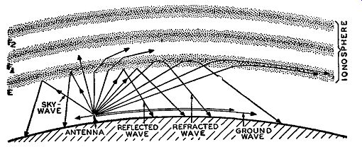
Fig. 5-13. The ionized layers of the ionosphere reflect or refract radio
waves to a greater or lesser degree depending on the frequency of the
waves and other factors explained in the text.
These ionized layers play a very important role in the propagation of certain radio waves. The layers tend to reflect or refract certain radio waves, in varying degrees, back toward the earth. A picture of this will make this analysis clearer. In Fig. 5-13, a number of different radio waves are shown being radiated from an antenna. These radiated waves consist of ground and sky waves. The sky waves are seen to be "reflected" by the E ionized layer in some instances and refracted in others. The refracted waves reach the earth quite a distance from the antenna. However, frequencies above 30 mhz or so will not be reflected or refracted by the ionosphere except in rare instances. It may be thought at first that frequencies in the a-m broad cast range can make use of the ionosphere as a means of propagation.
This is not true during the daytime, because that layer of atmosphere just below the E layer of the ionosphere absorbs a great deal of the energy radiated at these frequencies, since this layer is somewhat ionized and has a higher pressure than the ionosphere. If the frequency of the waves is not too high and if the atmospheric region encountered is of low pressure and has a high degree of ionization, the radio wave may be reflected or refracted and returned to the earth. However, if the frequency of the wave is quite high, as with FM signals, the layers of the ionosphere will not reflect or refract the sky layers but will allow them to pass through to outer space.
Thus sky waves of different frequencies are affected variously by the layers of the atmosphere. When a signal of low frequency (long wavelength) is radiated from an antenna, it travels at a certain velocity. Upon reaching the ionosphere, it is temporarily retarded and returned to the earth from a lower part of the ionosphere than a high frequency signal (short wavelength). Therefore, the distance a sky wave can travel depends upon its frequency. The density of ionization of the layers increases with distance, and as the frequency is increased, the wave pierces deeper and deeper into the ionosphere until it reaches a point where it is reflected. or refracted back to the earth.
Consequently, it is evident that some relationship exists between the density of the ionized layers and the frequency of an electro magnetic wave, such that at some point the wave will be returned to earth. Since the density of these ionosphere layers (often called the electron density) is fairly constant during certain seasons and during parts of the 24-hour day, there exists some limit as to how high the frequency of the sky wave can be and still be reflected by the different layers of the ionosphere. This limitation is called the critical frequency, and a critical frequency exists for each ionized layer with respect to its electron density.
Under the foregoing circumstances, a-m broadcasting stations use the ground waves as the chief means of propagation during the day time, and the FM signals are the horizontally directed wave and also the ground reflected wave. It is difficult to use the direct ground wave above the a-m broadcasting frequencies became, as the frequency of transmission is increased, the ground wave becomes more and more attenuated and cannot be used for communication, except over extremely short distances. The sky wave plays a very important role in propagation between 1.6 and 30 mhz and makes possible long distance reception due to the reflected and refracted waves from the ionosphere.
As mentioned before, at frequencies above about 30 mhz reliable reception by means of the sky wave is no longer possible. At these frequencies the sky wave is not always bent back toward earth by the ionosphere, but instead frequently passes right through and is lost in outer space. Note that this loss of the sky wave is the essential difference between the propagation of waves above and below 30 mhz.
There is, of course, no sharp transition at this frequency.
At frequencies above 30 mhz, which is the range of most FM signals, the ground wave is attenuated even more rapidly than at the lower frequencies. This greater attenuation of the ground wave for v-h-f signals is a result of the losses which are caused by the currents induced in the earth near the surface. These same ground losses are also present at the lower frequencies, but the ground wave for the v-h-f range is more rapidly attenuated because the induction effect becomes greater as the frequency is increased.
The effect of this loss of the sky wave and the rapid attenuation of the ground wave is to limit the range of a transmitter working at very high frequencies to the horizon range of the transmitting antenna. This is so when the receiving antenna is practically at ground level, as is the case in many home installations. By horizon range is meant the distance the wave travels from the transmitting antenna to the horizon as viewed from the antenna. With this definition of horizon range, it is immediately seen that by increasing the height of an antenna (by increasing the size of its mast or by putting the antenna on higher ground) the horizon range will, also, be increased.
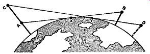
Fig. 5-14. The line of sight is shown between two antennas at A and
B. If the antenna A were raised to position C, the line of sight would
be ex tended to D.
Besides increasing the horizon range, raising the transmitting antenna also increases the line of sight. The line of sight is also increased when the receiving antenna is raised. Fig. 5-14 makes this somewhat clearer. Points A and B represent two antennas, one a receiving antenna and the other a transmitting antenna. Line AB represents the line of sight between these two antennas. The line of sight is the maximum distance that one can see from the top of one antenna to the top of the other antenna before the earth blocks out the view. In Fig. 5-14 this line AB just touches the earth at point X (it is said to be tangent at this point). If antenna A is raised to point C and if an observation from the top of point C is made, the line of sight between the two antennas is said to increase. By this is meant that, if antenna B is moved so that from the top of antenna B to the top of antenna C a new line of sight is formed, this line of sight would be greater than AB. This is shown in Fig. 5-14 where point D represents the new position of antenna B and point Y is the point where the new line of sight just touches the earth. From this diagram the new line of sight is equal to line CD which is seen to be greater than the old line of sight AB. It will also be noted that the horizon range has also been increased from distance AX to distance CY. Propagation of FM signals can cover distances beyond the line-of sight range when the effective radiated signal from the antenna is strong (that is, either a high powered transmitter or an FM antenna with a high power gain, or both). This is primarily caused by the directed FM radiated signal undergoing diffraction and refraction as it travels toward the receiver over the curvature of the earth, which means it is not following exactly a straight line path. This is a result of the nature of the atmosphere (principally the troposphere) at different distances from the earth.
At night the effects of the sun's rays are diminished to such an extent that the layer of atmosphere just below the ionosphere, which heretofore has absorbed the a-m broadcast signals, loses its absorption characteristics. Therefore, a-m broadcast frequencies can use the ionosphere as a means of travel during the night. In other words, during daylight the frequencies of the a-m broadcast band use the ground wave as a means of propagation, and at night they use the sky waves as well, as a means of propagation via the ionosphere. Since sky waves, compared with ground waves, can effectively travel over longer distances from the transmitting antenna with smaller losses in field intensity, it is readily seen that a-m broadcasting coverage at night can be much greater than during daylight.
SERVICE OR COVERAGE AREA OF FM
Now that we have covered the essential details as to how electro magnetic radio energy can be propagated through space, we should know something about the coverage or service area of an FM station. In the section on FM broadcasting antennas it was shown that the radiated signal from the FM antenna is strongly directive horizontally, with very little vertical radiation. It was also shown that the horizontal radiation pattern is practically circular in shape, indicating that the coverage area is somewhat of the same shape. However, we do not know what relationship FM bears to the amount of area that can be covered (serviced properly) as compared with the coverage area of a-m signals. Since the FM signal is highly directional and depends primarily on its straight line path of propagation, with as little reflection from the ground as possible, a limitation exists as to the area it can service. However, due to inherent factors of the FM wave and the receiver design the coverage or service area of a station using FM is considerably more uniform than that of a station using AM This difference is not due to any difference in the manner in which the FM and a-m signals are propagated, but rather it is due to the decreased sensitivity of an FM receiver to noise and to interfering signals. These two factors combine to make it possible for an FM transmitter to cover a given area with more uniform freedom from noise and interfering signals, up to the horizon or line of sight range of the transmitter.
When amplitude modulation is used, the signal-to-noise ratio is high near the transmitter, but the intensity of the signal falls off rapidly as the distance from the transmitter increases. Furthermore, at points near the horizon limit of the transmitter, the signal strength may reach a point where man-made interference and natural static are comparable to the signal. Thus, the signal-to-noise ratio is correspondingly small and reception is noisy.
If we consider the same conditions using frequency modulation instead of AM, then we have a different situation. Near the horizon limit the signal is still just as weak as in the preceding a-m case. However, the receiver discriminates against the noise by responding only to the signal and not to the noise. Thus, the effective signal-to noise ratio is increased and reception is improved.
The ability of an FM receiver to differentiate between the desired signal and interfering signals on the same or adjacent channels is of great advantage in providing more reliable reception over the complete service area of the transmitter. Investigation discloses that in order to prevent an FM receiver from responding to an interfering signal, the desired signal must only be twice as strong as the interfering signal, whereas in AM the ratio has to be as much as 100 to 1, or even more, as was mentioned in Section 1. Provided this low ratio condition for FM is satisfied, the FM receiver will reproduce only the stronger signal and completely eliminate the weaker signal -- except where the interfering signal is on exactly the same frequency as the desired signal.
As a result of this condition, it is possible to assign stations to the same frequency when the geographical separation between the stations is relatively small and a large area is to be covered. This can be done without running the danger of interference between stations operating on the same frequency. There will be no interference provided that the frequencies and stations are so assigned and located that the desired signal will always be at least twice as strong as the interfering signal. An additional factor which makes FM economical of space in the radio spectrum is the ability of the receiver to discriminate against noise. This makes reception more uniform over the entire range of the transmitter, so that the distance between transmitters can be increased. As a result, fewer transmitters are required satisfactorily to cover a given area when FM is used.
One of the biggest problems in the coverage area of a-m stations is the question of night transmission. We have shown that during the night the frequencies of the a-m broadcast range are reflected from the ionosphere and, hence, cover greater distances than during the daytime. In other words, at night the propagated signals from these stations greatly exceed their daytime service area. Since this is so, many a-m stations that normally operate during the day have to close down at night for reasons of interference. The increased coverage area is so great that it overlaps the coverage area of other broadcasting stations and interference results in the receivers falling within the overlapped areas -- especially if the signal ratio between these two signals is less than 100 to 1. Due to the closing of many a-m broad casting stations during the night, there is a difference in the number of operating a-m stations within the a-m band during the day and night. In FM the situation is different. There can be as many FM stations on the FM band during the night as during the day. The reason for this is that FM signals are propagated in a uniform direction and do not use the ionosphere as a means of propagation at all. Consequently, all FM stations can operate 24 hours a day.
INTERFERENCE
In the discussion of the coverage area of FM compared with AM, we have to take into account interference effects with respect to these different types of transmission. We have discussed some features relative to interference at the beginning of this text and also in the pre ceding section of this Section. If a fairly good concept of interference with respect to both the a-m band and FM band is acquired, many a questionable point about the erratic operation of a-m and FM receivers will be understood.
A certain limit exists as to the area each broadcasting station can cover. For instance, a standard might have been set for a certain radio transmitting station not to exceed a field intensity of 1000 micro volts per meter at 25 miles from the transmitting antenna. It is, therefore, said that this station's coverage area is one of a 25-mile radius where a 1000 µv/m contour cannot be exceeded. In other words, the coverage area, besides being classified in to a circle of so many miles radius, is also classified by a field intensity contour within this circle which cannot be exceeded. These limitations act to prevent interference between stations operating within different service areas.
If the signal from any transmitting station interferes with a desired a-m signal at a receiving set, the ratio between the desired and un desired signal must be about 100 to 1, or greater, for the undesired signal not to interfere with the reception of the desired signal. In FM the situation is different, the ratio necessary being 2 to 1, or greater. From this simple analysis, it is seen that there has to be greater separation between the contours of a-m broadcasting stations than between FM stations. Hence, due to interference between stations, there has to be a greater frequency separation between transmitters operating on the a-m band. Therefore, a limited number of a-m broadcast transmitters exist throughout the country, some where in the vicinity of one thousand compared to the thousands possible on the present-day FM band.
These interference problems were discussed under daytime conditions, but under nighttime conditions the interference situation for AM is even worse, due to the extended coverage range of the radiated a-m signals. A number of things have been done to reduce this nighttime interference besides shutting down some stations during the night. Some of the special measures undertaken are to make the a-m antenna more directional at night in order to reduce the use of the sky wave, to reduce the power of the transmitter, and to increase the adjacent channel separation between stations operating within the same coverage area. The power of a transmitting station which is greatly interfered with may have to be increased so that the field intensity of the desired signal at the different receivers will be greater by a ratio of at least 100 to 1 than the undesired signal. In some cases the solutions designed to reduce interference also reduce the coverage area from what it was during the day, as when a directional antenna is used to offset interference at night.
Interference in an FM receiver which is within an area where two FM signals appear, is not nearly so serious as in AM First of all, the frequencies of the signals have to be somewhere near each other for perceptible interference to take place. Secondly, if the ratio of the desired to undesired signal is always greater than 2 to 1, no interference will take place if the two frequencies involved are separated by 200 khz, that is, operating in adjacent channels. When the interference is between two signals operating on the same channel frequency, the ratio has to be at least 10 to 1, or higher, to prevent interference. When the separation in frequency between the two interfering FM signals is 400 khz or more, there is less chance for interference.
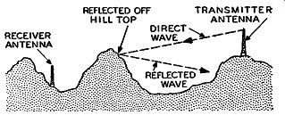
Fig. 5-15. If the receiving antenna is below an obstruction, as in the
sketch, the h-f radiation from the transmitting antenna will be reflected
instead of going to the receiving antenna.
Even though an FM receiver is located within a given FM station's coverage area, it still may be possible for the receiver to have very weak reception, or even no reception, on certain channels. This occurs when the directed wave from the antenna is reflected from some object and, therefore, does not reach an FM receiver on the opposite side of the object. This may occur frequently in hilly country or in cities where there are large buildings. The picture in Fig. 5-15 illustrates this case of reflection very simply. The directed wave is seen to hit the hilltop from which it is reflected and does not reach the receiver antenna. In those places where the transmitting antennas are fairly high and where the coverage area consists of reasonably flat terrain, FM reception will be most favorable.
From the discussion so far, it might be thought that it is not possible, under regular operating conditions, for FM signals to be propagated beyond their normal coverage range. It is, however, possible for something like this to occur under special atmospheric conditions. At times a change in the weather causes changes in atmospheric conditions not far above the earth, namely in the troposphere layer. These changes are such as to cause the characteristics of the gaseous material of certain parts of the troposphere to be changed, in which case the dielectric constant of that part of the troposphere also changes. This change in dielectric constant is great enough at times to cause high frequency waves to be reflected and refracted from the troposphere instead of passing through the atmosphere and being lost in outer space.
Since these abnormalities in the dielectric constant occur a reasonably short distance above the earth ( about one mile or so), it is possible for some FM waves, even though they are highly directive in the horizontal direction, to be propagated through space via this sky wave. Under such conditions, an FM signal may have sufficient signal strength to be heard outside its normal coverage area and can thus cause interference with other stations operating in a different coverage area.
It is also possible for interference to occur in FM receivers due to the harmonic of some other transmitter finding its way into a receiver which is tuned to an FM signal in a given coverage area. This can be shown by a typical example in reference to one of the ham bands. The frequency range of 50 to 54 mhz is allotted to amateur transmission by the FCC. Most types of emission are allowed to operate on this complete band with amateur FM allowed to operate only on the 51.0-to 54.0 -mhz portion of it. Since the commercial FM broadcasting range is between 88 and 108 mhz, it is readily seen that the second harmonic of these amateur frequencies can cause interference. In other words, the second harmonics of this amateur band of 50 to 54 mhz are 100 to 108 mhz and, if these second harmonics are strong enough, they can interfere with the regular FM commercial broadcasting stations transmitting at frequencies between 100 and 108 mhz. Since amateur transmitters have no particular coverage area, they may be located near enough to an FM receiver, so that field intensity of the second harmonic of this amateur signal (whether AM or FM) is strong enough to override the signal to noise ratio of the receiver and, hence, cause interference. That is, this undesired second harmonic signal can be so great in comparison with the desired FM signal from the commercial station that the ratio between the desired to undesired signal is less than 2 to 1.
The ability of an FM receiver to differentiate between the desired signal and interfering signals on the same or adjacent channels is of great advantage in providing more reliable reception over the complete service area of the transmitter. Investigation discloses that to prevent an FM receiver from responding to an interfering signal, the desired signal need be only twice as strong as the interfering signal.
Provided this condition is satisfied, the FM receiver will reproduce only the stronger signal and completely eliminate the weaker signal.
QUESTIONS
SECTION 5
5.1. Why is it important to have no phase distortion introduced in the transmitted FM signal by the FM transmitting antenna?
5.2, a. What is meant by horizontal polarization of a radiated signal? b. How should a dipole antenna be positioned for horizontal polarization of its radiated signal?
5.3. a. To reduce the amount of radiated power in the vertical direction (that is toward the atmosphere and ground) are the elements or bays of an FM broadcasting multielement antenna stacked vertically or horizontally apart from each other?
b. For a multielement FM broadcasting antenna, what can be done to make the radiated signal more concentrated in the horizontal direction? Assume no change in the transmitter power output.
5-4. a. If an antenna has a power gain of 5 and the power output from the transmitter equals 2.5 kw, will the radiated power from the antenna be 5 X 2.5, that is 12.5 kw? Explain your answer.
b. What is the antenna field gain when the power gain is 5?
5.5. For a four-bay circular antenna, what is the angle of elevation from the horizontal for the vertical component of radiated· signal at a point where the relative field intensity is 0.6?
5.6. For a square-loop antenna employing ten loops separated from each other by 340 electrical degrees, what is the power gain of the antenna with respect to a half-wave dipole?
5-7. In what form are the ionized layers of the ionosphere distributed?
5-8. What is meant by the critical frequency of the sky wave and upon what does this frequency depend?
5-9. Why is a-m broadcasting coverage greater during the night than during the day?
5-10. a. Define line of sight.
b. How can the line of sight between an FM transmitting and receiving antenna be increased?
5-11. Why are there fewer a-m stations operating at night than in the daytime?
5-12. Can the greatest number of transmitting stations be employed in the a-m broadcast band or the FM broadcast band? Why?
5-13. In FM reception when must the signal strength ratio of the de sired to undesired signals be at least 10 to 1 in order to prevent interference?
5-14. Under what conditions can an FM signal be received outside its normal coverage area?