THE problem of subjugating noise and hum, ever present in audio circuits, is especially acute in a high-gain device such as the tape recorder. Although much that has been written on eliminating noise and hum in audio devices also pertains to the tape recorder, the subject is too important to be treated lightly or dismissed altogether in these pages on the grounds that it has been covered elsewhere.
In tape recorders it is generally the playback rather than the record mode which governs the amounts of hum and noise that are heard, assuming equal precautions are taken in each mode.
Playback is ordinarily the limiting factor because of the relatively low signal levels presented to the input stage compared with noise and hum generated in this stage.
When recording from high-level sources such as radio tuners, TV sets, piezoelectric phonograph cartridges and audio control amplifiers, the input signal to the tape recorder is about 0.5 to 2 volts on peaks. Compared with hum and noise in the input stage, using a suitable audio tube, these levels are very substantial.
When recording from a microphone, the available signal is considerably lower, about 10 to 30 my on peaks. Yet in playback the signals presented to the input stage are still lower.
The peak playback signal is at most 10 mv, occurring in the region of 3,000 hz at 7.5 ips. More likely, in a machine where record level is kept suitably low to confine distortion to reason able bounds, peak output is about 5 my. At lower and higher frequencies, output is much less than 5 to 10 mv.
Due to the fact that the playback head is a velocity device-output varies directly with frequency-the signal presented by the playback head to the input stage is a small fraction of 5 to 10 my over much of the low range. Thus at 50 hz the signal level is about 36 db below that at 3,000 hz, or about 1/6 to 1/12 mv.
At the high end, two factors contribute to declining signal output above 3,000 hz or so. First, the recorded frequency characteristic declines in the treble range. Second, there is a falloff in audio energy at the upper end of the spectrum. Altogether over much of the audio range the peak signals fed to the input stage of the playback amplifier approach 1 mv or less.
This holds especially true at the frequency extremes, thereby accentuating the problems of noise and hum.
For the reasons just indicated, the following discussion will revolve about noise and hum that occur in the playback mode, chiefly in the playback amplifier. However, it should be under stood that what is said applies equally to the record amplifier. The discussion will deal with principal sources of noise and hum and with means of combating each. No reference will be made to mechanical noise produced by the transport mechanism, which is an entirely different subject. But electrical noise which originates in the transport and appears in the amplifier output will be discussed.
Sources of noise
For present purposes, noise may be defined simply as unwanted sound, other than 60-cycle hum and its harmonics. For the most part noise consists of evenly distributed frequencies, which include the audio range and beyond. At the high end of the audio spectrum there are more frequencies per octave' than at the low (for example, there are more frequencies between 5,000 and 10,000 hz than between 50 and 100 hz). Therefore noise composed of evenly distributed frequencies sounds high pitched or hissy. Noise may also include pops, crackles and other extraneous frequencies that may appear for one reason or another.
Random motion of electrons in a circuit causes what is known as thermal noise, increasing with temperature. The signal voltage produced by thermal noise is proportional to the square root of the impedance of the signal source.
[An octave is a two-to-one frequency ratio.]
Tube noise is chiefly of two kinds, thermal and microphonic.
Thermal noise refers to the random arrival of electrons at the plate. Microphonics refers to the fact that mechanical vibration of the tube results in minute changes in spacing between tube elements, causing variations in signal output, manifest as noise.
The tube behaves as a microphone does, which produces a signal due to displacement of its elements.
The principal types of thermal tube noise are shot, flicker and partition noise. Shot noise refers to the fact that the flow of electrons from cathode to plate does not take place in a steady stream; the signal output of the tube reflects this variation in current flow. Flicker noise is similar, except that instead of covering the entire audio spectrum, as does shot noise, it is confined principally to frequencies below a few hundred hz. The reasons for flicker noise are uncertain. Partition noise occurs in the case of pentodes and is caused by the division between plate and screen of electrons flowing from the cathode. Tube noise can also be caused by various tube defects, as in the case of a gassy tube or one with low leakage resistance between elements.
Thermal agitation of electrons causes resistors to be an important source of noise. Such agitation produces a minute current flow, representing noise. The larger the resistance, the greater the resultant noise voltage across the resistor.
Tape noise may be of several sorts. The principal offender is modulation noise. This arises from physical irregularities in the thickness of the base or coating as well as from magnetic irregularities in the coating. When an ac or dc magnetic field is applied to the tape, these irregularities are reproduced in the recorded flux and are equivalent to noise. An ac magnetic field is, of course, produced by audio currents in the record head. Sources of dc fields are magnetized heads and an asymmetrical bias waveform; the departure from symmetry in effect represents a dc component in the record and erase heads, with a corresponding dc field. Modulation noise caused by the audio signal varies in amplitude with signal levels. Modulation noise produced by a dc field is a more or less steady hiss.
Pops and crackles may occur because the bias waveform is not a pure sine wave but contains harmonic distortion. The principal offender in this respect appears to be second-harmonic distortion.
Imperfect erasure may be responsible for two kinds of noise.
If the tape has previously been recorded, the erase-head field may not be sufficiently strong to remove completely the old signal, which competes in the background with the new signal, being especially obtrusive during quiet passages of the fresh recording.
On the other hand, erasure may be strong enough to remove all audible traces of the old signal, but, due to an asymmetrical wave form, it will produce modulation noise because of the effective dc produced by this waveform.
Print-through may be listed as a form of noise. The signal on one layer of tape may be magnetically transferred to an adjacent one because the recorded flux on the first layer passes through the adjoining tape. This effect is usually noticed only at relatively high recorded levels. Heat and length of storage tend to increase the effect.
The transport mechanism may cause clicks to be recorded on the tape due to sudden current surges when motors are switched on or off.
Tape recorders require a substantial amount of treble boost, and optimum design calls for all or nearly all this equalization to be supplied when recording. Treble boost should be used in play back only to the extent necessary to compensate for losses in the playback head (within reason). Some recorders, however, divide the total required treble boost equally between record and playback. The result is to emphasize not only the high audio frequencies in playback, but also tape noise and noise in the input stage of the playback amplifier.
Noise can be impressed on the tape in the form of a loud click or pop due to sudden application of plate voltage to the tube that drives the record head or due to sudden removal of this voltage.
Sources of hum
The playback head has an appreciable amount of inductance and is therefore susceptible to minute magnetic fields (caused by power-line current) which induce a corresponding hum voltage in the winding. This poses one of the most serious threats to satisfactory tape reproduction. Signal output of the head is so low in the region of 60 hz that 70-db or more gain is required for amplifier output of 1 volt. Consequently, any hum induced in the head is greatly magnified.
Hum pickup by the playback head is mostly at the power-line frequency, ordinarily 60 hz. However, harmonics of 60 hz may also affect the head. For example, power transformers or motors, as well as their leads, radiate a substantial amount of third harmonic, namely 180 hz.
In the tape amplifier, second-harmonic hum of 120 hz can be a problem due to insufficient filtering of the B-plus supply. The principal problem, however, is hum pickup at the grid of the first tube in the playback amplifier. Hum here is mainly 60 hz, although harmonics may also be present in substantial quantity.
Hum pickup by the input tube of the playback amplifier may be due to a variety of factors:
1. Imperfect isolation appears between heater and cathode. Due to internal and external capacitances between these two elements, some coupling exists between heater and cathode. In the case of an ac-operated heater this can permit a significant amount of the 60-cycle voltage to reach the cathode. Since a tube will amplify an ac voltage at its cathode if the cathode is not perfectly at ac ground, the result may be a fair amount of hum in the tube's output. Similarly, there exists a leakage resistance between heater and cathode that can result in hum. Leakage resistance not only occurs within the tube but is also due to materials used in the socket, to materials used in the base of the tube and even to the insulation used on wires connected to the socket terminals.

Fig. 1001. Hum due to heater-cathode capacitive reactance.
Fig. 1001 shows how hum may be impressed on the cathode by an ac-operated heater. Assume that at 60 hz there is a 2,000-megohm leakage reactance due to capacitance from one end of the heater terminals to the cathode and a 3,000-megohm reactance from the other terminal to the cathode. These leakage reactances result in the cathode being nearer to the polarity of heater terminal 1 than terminal 2. In other words, due to unequal leakage reactances, the opposite polarities at the heater terminals do not cancel at the cathode. As Fig. 1001 shows, the center tap of the heater winding of the transformer is effectively connected to ground, physically or through a large capacitor. Thus there is a 60-cycle voltage between cathode and ground. The impedance between cathode and ground acts as a voltage divider in series with the parallel leakage reactances (1,200 megohms) so that the larger the value of the cathode-to-ground impedance the greater the hum voltage at the cathode.
2. Imperfect isolation between the heater and grid results in heater-grid leakage resistance and capacitive reactance. As in the case of heater-cathode leakage, when heaters are ac-operated, an unbalanced resistance or reactance between each heater terminal and the grid results in an ac signal on the grid, with resultant hum in the tube output. The grid resistor acts as a voltage divider in series with the leakage resistances or reactances and, being usually in the order of 0.25 to 1 megohm, can result in a significant amount of hum voltage at the grid.
3. Current traveling through a conductor produces a magnetic field around it. If another conductor is in the presence of a changing magnetic field, a voltage will be induced in that conductor. Thus, the ac-operated heater coil produces a 60-cycle magnetic field which may cut through the grid and induce a corresponding voltage in it.
4. Hum may result from other magnetic fields affecting the grid. Motors, chokes, transformers and leads carrying substantial amounts of alternating current (heater and power-line leads) can produce such magnetic fields. A rectifier tube, such as a 5U4-GB, can sometimes produce a magnetic field-in this case changing at a 120-cycle rate-with sufficient strength to affect significantly a close-by low-level audio tube.
5. There may be sufficient capacitance between the grid, grid lead or other grid components and adjacent 60-cycle leads (heater and power line) to cause hum voltage to appear at the grid.
6. Hum may be picked up by a transformer connected between the playback head and the grid of the first playback tube. In some tape recorders using low-impedance playback heads which have a low output voltage, the signal is stepped up by a transformer before going to the grid. Transformers are sensitive to magnetic hum fields and, unless exceptionally well shielded and carefully mounted and oriented, they may be a potent source of hum. The same applies to transformers used with low-impedance micro phones in recording.
7. Hum may be due to an ac heater which is not effectively grounded at 60 hz.
While this list includes most of the major sources of hum in a tape recorder, it is not all-inclusive. For example, hum may result from a chassis voltage gradient. For instance, the chassis may be used as a conductor for 60-cycle current in place of one heater lead to each tube. As a result, there are voltage drops between various points on the chassis because the chassis does have some resistance. If the chassis is used as the ground lead for a low-level signal, then the 60-cycle voltage due to the alternating current and chassis resistance is included with the low-level signal and amplified along with it.

Fig. 1002. Formation of a hum-inducing ground loop.
Another example is hum pickup due to a ground loop, which can occur when more than one ground return is used between two points. Assume there are two ground returns between a voltage source and a tube, as shown in Fig. 1002. These duplicate ground leads in effect form a shorted turn or ground loop. In the presence of a 60-cycle magnetic field a 60-cycle voltage is induced in the ground loop and is amplified by the tube. Similarly, there is the so-called wiring loop which results when the hot and ground leads of a signal source are too widely separated; these two leads, as in the case of a ground loop, form a turn in which a voltage can be induced by a magnetic field.
Although this discussion of hum sources has pointed at the first stage of the playback amplifier, it is obvious that a bad case of hum pickup in later stages can also affect performance adversely.
Combating noise
In the matter of tube noise, there are four steps which can be taken by the designer (and perhaps by the user):
1. A tube type can be chosen which is known to possess good noise characteristics. But some tubes that are desirable with respect to noise may be undesirable with respect to other characteristics such as hum, distortion and gain. Consequently, a tube cannot be chosen on the basis of noise properties alone. However, a number of tubes are available, some of them developed specifically for audio applications, which tend to be generally satisfactory. These include the 5879, 6SJ7-GT, 6J7-GT, the 6F5-GT, 12AX7, 12AY7, 6AU6, and foreign Z729, EF86, etc. Among these and several others the designer of a tape amplifier can find one that comes close to satisfying his particular requirements.
2. Although a given type may on the average be substantially less noisy than run-of-the-mill tubes, it is still usually necessary to employ a selected tube for the input stage. Sometimes the designer uses the input tube type for other stages as well, thus giving several specimens from which the owner can select the best for the input stage.
3. Noise produced by a tube varies with the manner in which it is operated. Shot noise varies inversely with transconductance (gm)2. Since gm can generally be increased by operating the tube at moderately reduced heater voltage, such operation is a means of lowering shot noise. Shot noise also varies inversely with plate current. Thus noise can usually be minimized by increasing plate current within practical limits, which necessitates a high B-plus supply voltage and/or relatively low value of plate load resistor.
4. Tubes can be shock-mounted to minimize microphonics.
Noise due to thermal agitation in resistors can be reduced by using low-noise types, a characteristic usually associated with precision resistors. These are generally either deposited carbon or wirewound. Of the two, the wirewound are generally less noisy and more stable in value. Not all precision carbon resistors are de posited carbon, and therefore not all are low noise types. Some precision resistors are made from regular molded carbon ones by scraping away enough of the carbon to bring the resistance up to a specified value. Although this is not a common practice, it does occur.
Resistor noise can also be limited by using large-wattage values.
Thus if a 2-watt resistor is used where a 1/2-watt one would ordinarily do, there is better dissipation of heat and consequently less thermal agitation. Even where no current flows, as in the case of grid resistors, high-wattage resistors tend to produce less noise.
The need for a low-noise type is greatest in the case of the plate load resistor. However, for best results, it is also advisable to use low-noise types as grid resistors and as unbypassed cathode resistors. What is sometimes done is to use a wirewound resistor as the plate load and deposited carbon units as grid and unbypassed cathode resistors. In subsequent stages, where the problem ...
----------------
A lower heater voltage reduces the space charge (electron cloud) at the cathode.
'This means that the grid voltage has relatively greater effect upon the current flowing between cathode and plate.
----------------
... is less acute, insurance against noise can be purchased at relatively little increase in cost by using 1- or 2-watt resistors as plate loads.
Wirewound resistors should be of the noninductive type, otherwise there may be some induced hum pickup. Making a wirewound resistor so that winding inductances cancel is a fairly complex procedure; moreover, at high ohmic values the only wirewound resistors generally available are precision ones-which helps account for their costliness.
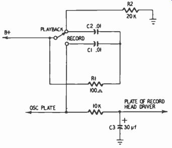
Fig. 1003. Method of preventing switching transients.
Tape noise due to head magnetization may be avoided in part by circuitry that prevents sudden introduction or removal of audio, bias or erase currents through the record and erase heads, causing magnetization. The same measures also prevent clicks or pops being recorded on the tape due to such current surges.
Fig. 1003 shows a typical circuit that causes B plus to be gradually applied to or gradually removed from the oscillator and record-head driver stages when switching between the record and play back modes. When switching from record to playback, electron flow in the record-head driver and oscillator circuits continues briefly through R1 and C1 into the B-plus line until C1 is charged. When switching from playback to record, arcing is pre vented at the playback terminal by the continued flow of electrons through R2, C2 and R1 into the B-plus line until C2 is charged.
The plate voltage of the record driver stage rises slowly due to the time required to charge filter capacitor C3.
A further means of preventing head magnetization is for the oscillator waveform to be as close as possible to a pure sine wave, with a minimum of asymmetry; such asymmetry is in effect a dc component that magnetizes the head.
Some degree of head magnetization is inevitable, if only because of the natural asymmetry of audio waveforms. Therefore it is incumbent upon the user to demagnetize the heads occasionally with an electromagnet (powered by a 117-volt line) designed for this purpose. Too powerful an electromagnetic field may cause injury to a nearby record-level meter.
Where imperfect erasure is a noise source, the difficulty may lie in too high a record level, one productive of excessive distortion as well as insufficient erasure. But if the fault lies in the inadequacy of the erase head or elsewhere in the erase circuit, one way of bypassing this fault is to use a bulk eraser. However, if the tape is dual track, as is generally the case in home use, it is of course impossible to erase one track with a bulk eraser without erasing the other as well.
If print-through is the problem, it may be necessary to avoid excessively high record levels and to avoid storing tapes in places of high temperature or near magnetic fields. Print-through is a property of the tape rather than a fault of the recorder.
Noise on the tape due to switching transients can be avoided by placing capacitors across switches that actuate the transport motors, across relay contacts and the like. These capacitors pre vent the sudden interruption of current flow, which may intro duce transients into the tape amplifier.
Location and setting of the gain control can be a factor in controlling noise. Placement of this control at a relatively late stage in the amplifier means that cutting down signal level simultaneously reduces noise from the early stages as well. On the other hand, the control should not be so far from the first stage that signal levels become large enough to produce distortion.
In playback it is frequently best to operate with the playback gain control full on, if this is practicable and will not overload following equipment. This permits gain to be reduced in the following audio equipment, at the same time attenuating noise in stages following the recorder's gain control.
Combating hum
Hum pickup by the playback head can be eliminated in large measure by enclosing the head in a heavy magnetic shield. Fig. 1004 shows a high-quality tape recorder equipped with such a shield. These are usually made of Mumetal and have openings just wide enough for passage of the tape. Magnetic fields in the vicinity of the head are shunted around the head by the shield.
Moderate-price tape recorders seldom employ massive and expensive shielding such as shown in Fig. 1004. Instead, they depend upon the shielding ability of the magnetic material in which the head is encased. A primitive but quite effective way of immunizing the head from magnetic fields is illustrated in Fig. 1005. Here a small piece of magnetic material (a silicon steel I-plate from a junked power transformer) has been placed near the record-playback head of a moderate-price recorder. The steel is about 3/4 inch wide and 2 inches long after being bent double.

Fig. 1004. Head shield used on professional-quality recorders.
It clamps like a hairpin onto the bracket which holds the heads and guides the tape. The metal serves to warp the magnetic field surrounding the playback head so that fewer lines of force cut through it. The position shown in Fig. 1005 was determined by trial and error as the best feasible one.
Regardless of the type of shielding used for the heads, precautions should be taken to keep components producing substantial magnetic fields as far removed from the heads as possible. Sources of such fields include the power transformer, chokes, capstan and reel motors, and relays. Orientation of these components can substantially reduce hum pickup. Furthermore, the type and quantity of magnetic shielding used to enclose these components deter mine the amount of magnetic flux emanating from them.
Partly as a means of conquering the hum problem, most play back heads are equipped with dual windings, so wound that when they are properly connected in series not only is output augmented but induced hum voltages tend to cancel (Fig. 1006). It may be seen that the two windings are in series so far as signal voltage is concerned but that the hum polarity is the same at both output terminals, resulting in little or no hum voltage.

Fig. 1005. "Gimmick" used to minimize hum pickup by playback
head of a moderate-price tape recorder.
Elimination of second-harmonic hum (120 hz) in the amplifier requires fairly extensive filtering of the B-plus supply. Generous-size capacitors should be used, particularly in filter stages nearest the rectifier tube. B-plus supplies to low-level amplifier stages should go through three or four filter stages. Fig. 1007 illustrates a typical well-filtered B-plus supply.
Hum resulting from heater-cathode leakage resistance or reactance, heater-grid leakage resistance or reactance and the magnetic field produced by the heater coil (some tubes have a coiled heater to minimize hum radiation) can be obviated in part by choice of the proper input tube for the playback amplifier (and also, in addition, for the record amplifier). The 5879, Z729, EF86, 12AY7 and others are specially designed for audio applications, with hum as well as noise reduction a prime design consideration. Tubes such as the 6F5-GT and 6J7-GT have an external grid located at the top of the tube to remove the grid from hum sources.

Fig. 1006. Hum-bucking effect produced by series connection of dual
windings.

Fig. 1007. Example of a well-filtered B-plus supply in a tape recorder.
There is usually a substantial variation in hum even among tubes of the same type specially designed for low hum. For example, in a group of seven 5879 tubes tested by the authors, there was a 15-db variation from the best to worst with respect to minimum hum obtainable when the heater was ac-operated.
Hum due to heater-grid or heater-cathode leakage or to the magnetic field created by the heater coil can sometimes be reduced by operating the heater at reduced voltage, say 5.8 volts or so in the case of a 6.3-volt tube.
The extent to which the tube is affected by nearby magnetic fields depends partly upon the tube itself and partly upon how it is situated with respect to components producing these fields.
Tubes with metal rather than glass envelopes, such as the 6F5-GT, 6J7-GT and 6SJ7-GT, have built-in shielding against magnetic fields. Glass tubes in low-level stages should be protected by slip over metal shields which make secure contact with ground. Care should be taken in design layout to keep power transformers, chokes, motors and the like a suitable distance from the input tube. A transformer mounted above a steel chassis rather than flush with it is likely to radiate less hum because when it is flush mounted the chassis acts as an extension of the laminations, radiating hum. Aluminum chassis are preferable to steel in that they do not radiate hum and have lower resistance to circulating currents. Substantial benefits are sometimes obtained by putting the power supply on a separate chassis.
Sometimes a reduction in hum can be effected by demagnetizing the amplifier tube and its shield. Using a bulk eraser or other fairly powerful ac electromagnet, the tube and also the shield are brought into the magnetic field and slowly withdrawn. If the electromagnet is a very powerful one, do not bring the tube so close as to dislocate its elements.
Other things being equal, hum may be greater in a pentode than in a triode because the division of current between plate and screen of the pentode varies in step with a 60-cycle magnetic field. Triodes are less susceptible than pentodes to whatever 120 cycle hum may be present in the B-plus supply. Fig. 1008 helps explain why. The plate resistance of the tube and the load resistor form a voltage divider so that a portion of the 120-cycle hum voltage is present at the tube output. Since triodes have relatively low plate resistance-roughly 10,000 to 80,000 ohms compared with about 1 megohm for pentodes-the portion of the 120-cycle voltage that appears across a triode tube is less than that across a pentode. On the other hand, the possible need for an additional amplification stage, due to the lower gain of a triode, may offset the initial advantage of using a triode.

Fig. 1008. Reduction of 170-hz hum by use of a triode.

Fig. 1009. Typical method of reducing hum by putting dc bias on the
heaters.
Heater-cathode leakage is aggravated by the fact that the cathode is usually at a positive potential, tending to attract electrons emitted by an ac-operated heater. An often-used countermeasure is to bias the heater with about 20 to 50 volts of B plus (Fig. 1009) so that the cathode is no longer positive with respect to the heater.
Sometimes the heater is connected to the cathode of the power output tube in a tape recorder containing a power amplifier and speaker. Furthermore, it is advisable to bypass the cathode with a large capacitor (a low-voltage electrolytic having several hundred microfarads capacitance) so that any 60-cycle ac at the cathode is completely shunted to ground.
Where heaters are ac-operated, the heater winding of the power transformer usually has a center tap which is physically grounded to balance out hum. Alternatively, the tap may be connected to a dc potential, as was shown in Fig. 1009. The heater is still at ground so far as ac is concerned due to the large filter capacitor at the B-plus takeoff point. The theory behind the center tap is that, since the grid of the tube is also at ground through the grid resistor, hum voltages reaching the grid from the heater terminals are of opposite polarity with respect to ground and hence cancel.

Fig. 1010. How the balancing potentiometer cancels hum.
However, it is not necessarily true that the grid is at ground so far as hum voltages are concerned. As illustrated in Fig. 1010, there may be leakage between the grid and a 60-cycle source, such as a motor, which results in a small amount of 60-cycle voltage on the grid. Fig. 1010-a assumes a 5,000-megohm resistance between the ac source and the grid and also a 10,000-megohm resistance between each side of the heater and the grid. The grid resistor R2 is 1 megohm. R1 and R2 form a voltage divider, resulting in a small voltage at the grid. For easy illustration, assume that through leakage the external source causes +2 volts to appear on the grid at a given instant, although actually the voltage will be far less. The hum-balancing potentiometer shown in Fig. 1010 places an opposing voltage of-2 on the grid. Fig. 1010-b is a redrawn circuit showing how this is accomplished. The slider of the pot goes to ground so that the voltage at each heater terminal is referred to ground, or 0. Assume 6 volts across the heater and that the slider is positioned so the lower heater terminal, at a given instant, is +1 and the other terminal -5 volts.
R3 and R4 constitute a voltage divider. Since they are shown equal, the voltage at the midpoint is halfway between +1 and-5, or-2 volts, and has a source impedance of 5,000 megohms.
Hence -2 volts is applied to the grid, balancing out the +2 volts impressed by another hum source. If R3 and R4 were unequal, then the slider would have to be positioned slightly differently to cancel the hum voltage at the grid of the tube.
If the slider in Fig. 1010 were returned to a B-plus point instead of directly to ground, as shown in Fig. 1009, nevertheless the large filter capacitor at this dc point would place the slider at ground so far as ac is concerned.

Fig. 1011. Typical dc heater supply.
The hum voltage shown at the grid in Fig. 1010 does not necessarily arrive from an external source such as a motor, power transformer, etc. It may be due to heater-cathode and heater-grid leakage resistances and reactances or to the effect of magnetic fields upon the grid leads and grid resistor, etc. However, the hum-cancelling action is basically the same as that in Fig. 1010.
At all events, if an ac heater supply is used, the supply must be connected to ground in some manner because a floating heater will result in a relatively tremendous amount of hum. Stray capacitance or leakage resistance will cause high voltage ac present at the secondary of the power transformer with respect to ground to appear at the adjacent heater winding unless the latter is also at ground.
To prevent the heater from being a source of hum, a dc heater supply is often used (Fig. 1011). Although this is generally a very effective measure, it is not necessarily superior to an ac supply in conjunction with a hum-balancing potentiometer. If the heater and its leads are the only source of hum, then the dc supply may result in only a few db less hum. On the other hand, if external sources, such as hum pickup by the playback head, stray capacitance between the grid of the input tube and ac power leads, magnetic fields, etc., are causing an appreciable amount of hum to appear at the grid of the input tube, then the balancing potentiometer may have an advantage because it can also cancel hum due to these external factors.
However, the balancing potentiometer is effective only for 60-cycle hum. Harmonics of the 60-cycle frequency that appear at the grid will not be cancelled. Therefore, the potentiometer is not a cure-all. Neither is the dc heater supply. Thus, all possible measures of hum reduction should be employed so that hum is at as low a level as possible before the balancing potentiometer or dc heater supply is called upon to do its work. It is unwise to rely heavily on hum cancellation.
If ac is used on the heater of the input tube, a helpful measure against hum is to shield the grid pin of the tube from the heater pins. This can be done by mounting vertically a flat piece of metal, connected to ground, so that it isolates the grid pin from the others (Fig. 1012).
Adequate shielding of the signal lead from the playback head to the input grid is important. In moderate-price recorders, a shielded cable with a single inner conductor is ordinarily used.
The shield wire should be connected to ground at an experimentally determined point near the input tube and not to a random position on the amplifier or transport chassis. A separate, heavy ground connection should be made between the transport and amplifier chassis if these are not an integral unit. In some recorders, to increase protection against hum, a shielded cable with two inner conductors is used. The two playback-head leads are connected to the two inner conductors, and one of these leads, together with the shield, is grounded at the amplifier.
Lines bearing alternating current should be dressed away from grids and other tube components, special attention being given to low-level circuits. Such lines, if traveling more than an inch or two, should be twisted so the magnetic fields surrounding each side of the line may cancel. The ac line should be dressed against the chassis so that the latter can act as a shield for the field surrounding the line. Running ac leads along the corner of a chassis is especially desirable for two reasons: First, this increases the amount of contact with the chassis which acts as a shield.
Second, it tends to maximize the distance between these leads and components subject to hum pickup. On occasion, running ac leads in a shielded cable may prove effective against hum.

Fig. 1012. Shielding the grid of a 64V6 input tube against hum.
Numerous measures can, and often should, be taken to minimize hum. A common ground point should be used for the low level stages; sometimes a ground bus is used for the entire chassis.
Leads, resistors and capacitors associated with low-level stages should be arranged as close to the chassis as feasible so that the chassis may serve as a shield for stray fields. The volume control should be separate from the power switch, although it is common practice in audio circuits to combine the two in one unit; the same injunction sometimes applies to the tone control, if any. A capacitor between one side of the power line and chassis may increase or decrease hum, depending upon which side of the line is involved. Reversing the orientation of the power-line plug in the line outlet often reduces hum a few db. A bottom plate for the amplifier can be helpful by acting as a shield with respect to external fields. Putting the power supply on a separate chassis can achieve a substantial amount of hum reduction, although this is generally not necessary if the power transformer is well shielded and properly located and oriented. As a final example of hum-combating techniques, some top-quality tape recorder design engineers have gone to the length of deliberately introducing hum of the proper amplitude and phase at some stage as a means of cancelling hum which other measures have failed to eliminate.