THE tape recordist may record at a level so high as to produce excessive distortion. Or, to avoid distortion, he may record at a level so low as to result in a poor signal-to-noise ratio. Given a good tape recorder, he can chart his way between these extremes with a fair but by no means lavish margin of safety.
The recordist steers his course by means of the record-level indicator. His success depends not only upon the type and quality of indicator used, but also upon the manner in which the indicator is connected to the record amplifier circuit, upon its calibration, upon avoiding the pickup of extraneous signals and upon his skill in interpreting what he sees.
While the principal function of the indicator is to guide in setting record level, two other important functions are usually performed if the indicator is of the meter type: metering play back level, and bias (and sometimes erase) current.
Types of indicators
Record-level indicators can be sorted into mechanical and electronic types. Mechanical indicators employ a dc micro-ampere or milli-ampere movement, the audio signal being converted to dc by a rectifier. Electronic indicators consist of either an electron-ray (magic-eye) tube or neon lamp, which may be driven directly by the audio signal or, in the case of the electron-ray tube, by a rectified voltage.
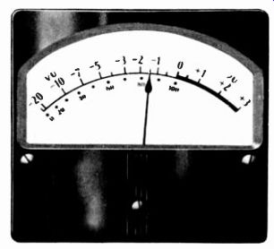
Fig. 901. Volume-unit (VU) meter showing A scale.
The principal type of mechanical indicator is the VU meter, very widely employed in professional audio work. However, not every meter equipped with a VU scale is a true VU meter, which must possess several specific characteristics. Although an operator can, with practice, acquire the knack of properly interpreting any meter, the VU meter has the advantage of standardization; it is a familiar item to those in professional work and therefore its readings have a recognized meaning.
At one time the volume indicator, sometimes referred to as a recording-level meter or decibel meter, enjoyed popularity, but is now in limited use. This and the VU meter have relatively high sensitivity and, since they contain their own rectifiers, may be driven directly by a moderate signal of less than 2 volts. Another variety of mechanical indicator employs a less sensitive dc meter and needs external amplification before rectification of the ac signal; this type may be referred to as a vacuum-tube voltmeter (vtvm). The foregoing all read average signal level. Still another vtvm type is designed to read peak level.
In the realm of electronic indicators, the neon lamp is most popular because it is least expensive. However, it does not provide as much information as the electron-ray tube and requires a good deal more audio signal to drive it.
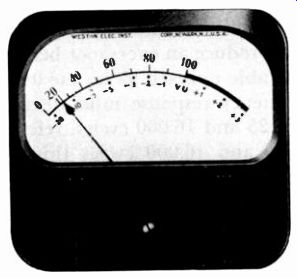
Fig. 902. meter with type B scale.
The VU meter
The VU meter (Figs. 901 and 902) contains a 50-microampere dc movement with a full-wave copper oxide rectifier. The standard meter has a 4-inch dial with a double scale. One scale reads from-20 to +3 VU. The other reads from 0 to 100 (percent); 100 coincides with 0 on the VU scale. The photos show these scales on two types of dials, one featuring VU units and the other the 0-100 graduation; these are respectively known as A and B scales. The A scale is ordinarily used in tape recorders.
VU units are simply decibels. Zero is an arbitrary reference level: 1 milliwatt of power passing through a 600-ohm resistance will cause a VU meter connected directly across this resistance to read 0 VU. This reading is referred to as 0 dbm; that is, 0 db above 1 mw in a 600-ohm line.
Although the reference level is 1 mw of power, VU meters are designed to be used with a power level which is 4 db above 1 mw, or 2.5 mw. In order that 2.5 mw in a 600-ohm line shall cause ...
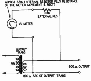
Fig. 903. Connection of a VU meter across a +4-dbm line.
... the VU meter to read 0, it is necessary to place a 3,600-ohm resistor in series with the meter, as shown in Fig. 903. The VU meter has a total resistance (microampere movement rectifier and internal resistor) of 3,900 ohms. Thus the total load across the 600-ohm line is 7,500 ohms.
The standard VU meter must possess certain dynamic characteristics when connected across a 600-ohm line, mentioned above.
The sudden introduction in the line of a sine wave with a power of 2.5 mw should produce an overshoot between 1 and 1.5%. The pointer should be able to reach 99 on the 0-to-100 scale within 0.3 second. The frequency response must deviate by no more than ±0.5 db between 25 and 16,000 hz, referred to 1,000 hz as 0 db. Between 35 and 16,000 hz this deviation should not exceed ±0.2 db. Distortion produced by placing the VU meter across a 600-ohm line should not exceed 0.3% harmonic. The meter must be able to withstand for 1/2 second a voltage 10 times that required to produce a 0 VU reading. It must be able to with stand continuously a fivefold voltage overload.
In professional work-recording, broadcast and motion picture studios-the VU meter is generally used (in series with a 3,600 ohm resistor) across a 600-ohm line. The maximum signal level in such lines is commonly designed to be 4 db above 1 mw, which causes the meter to read 0. However, in some instances the maxi mum level is 8 dbm, and in this case an appropriate attenuator is placed ahead of the VU meter to cause it to read zero at an 8 dbm level.
As a record-level indicator and as a means of measuring bias and erase current, it is of little or no importance what the VU meter means in terms of power in a 600-ohm line. This is of importance only in measuring playback level. For measuring record level, what is important is that a given point on the scale, usually 0 VU, correspond to the level producing maximum permissible distortion on the tape. For measuring bias or erase cur rent, a given point on the meter, usually 0 VU, should correspond to the correct amount of current. If the VU meter is so connected that it is in series with a 3,600-ohm resistor across a 600-ohm line when measuring record level, then the desirable dynamic characteristics of this instrument will be retained. When measuring bias or erase currents, which are steady, the dynamic characteristics are of no consequence and the meter can be used in any convenient manner.
(These considerations also pertain to meters other than the VU meter and need not be discussed further.) The VU meter indicates average signal level, and allowance must therefore be made for peaks.
The very high sensitivity of the VU meter is obtained by means of a special magnetic alloy with a large flux. Mounting the meter on a steel panel tends to shunt some of this magnetic flux, upset ting the meter's calibration. Therefore VU meters intended for such mounting must be specially calibrated by the manufacturer upon the basis of panel thickness.
The volume indicator
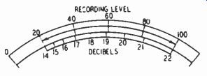
Fig. 904. Scale of a typical volume indicator.
Unlike the VU meter, this once-popular indicator is not standardized. Also, it has less sensitivity, requiring more than twice as much drive voltage. It is generally driven to a full-scale reading by 6 mw of power in a 500-ohm line. Speed of response, amount of overshoot, frequency range and distortion produced by placing the meter directly across an audio line vary according to brand and model. Moreover, the dial conforms to no standard. A representative dial is shown in Fig. 904, featuring a 0-to-100 scale and also containing a scale reading from 14 to 22 db. As in the VU meter, the volume indicator reads average level so allowance must be made for peaks.
Vtvm type indicator
The vtvm type indicator that reads average signal level generally uses a 1-ma movement, which does not necessarily incorporate the standardized speed, overshoot limits and other characteristics of the VU meter, although it may have a VU scale. A vacuum-tube amplifier supplies the current which is required after rectification to drive the meter.
Indication of peak rather than average signal level may be had by means of a circuit described later. Although this eliminates the necessity of making an allowance for the margin between average and peak signals, several reasons account for the limited use of this type of indicator, at least in the United States. One is simply that the professional operator has grown accustomed to reading a meter that shows average level and makes his judgments accordingly. The practiced operator, using a VU meter, can come within 1 db of the gain settings obtained by reference to a peak-reading instrument. Very often the operator is interested only in keeping distortion down over the average level and is quite willing to accept relatively large amounts of distortion on the short duration and comparatively infrequent peaks. Moreover, the peak-reading meter is less than perfectly accurate in its indication of peak level because some transients are not of sufficient duration to drive it to full indication.
The electron-ray tube
Fig. 905 illustrates the action of an electron-ray tube, the most popular type being the 6E5. When record level is sufficient to cause excessive distortion, the shadow of the eye is closed or nearly so. When the record level is too low for a satisfactory signal-to noise ratio, the shadow is wide open. Thus the recordist seeks that gain control setting which barely keeps the eye open. However, transients (rapid changes in signal level) are difficult to follow, and to make life easier for the recordist some tape machines incorporate a "floating action" which for a brief while keeps the eye near the peak levels reached.
The neon lamp
The neon-lamp indicator, almost always an NE-51, lights when the record level is high enough to cause undue distortion. How ever, it does not warn the recordist when the record level is too low. Therefore, some recorders employ two neon lights. One, labeled "normal" (or some similar term) is calibrated to light so long as the record level is adequate for a satisfactory signal-to noise ratio, while the other, labeled "distort," ignites when the record signal reaches a level producing excessive distortion. The recordist tries to set gain so that the normal light is on most of the time and the distort light is on seldom or never.
Mechanical vs. electronic indicators
Although more costly, mechanical indicators have an important advantage over electronic ones in that they inform the practiced operator in terms of decibels or percentage how much the record level is above or below the level producing maximum permissible distortion. Neon lamps only indicate when the level is too high or too low, but not by how much. The same is largely true for the electron-ray tube; while there is a variation from full shadow to no shadow, the range is not calibrated and its meaning is un certain.
A recordist may decide, for example, to set the record level 6 db lower than usual for a given type of music because past experience tells him /hat this is necessary to avoid excessive distortion due to unusually large peaks or because the type of music is such that distortion would be noticeable. He can reduce record level close to 6 db with the aid of a meter but not with the aid of an electronic indicator.
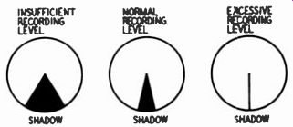
Fig. 905 Action of an electron-ray tube.
An advantage of the meter, particularly the VU meter, is that it is a relatively uniform product. In a given circuit, various meters of the same kind can be substituted and will produce essentially the same reading. In the case of electron-ray tubes and neon lamps, manufacturing tolerances are large enough so that individual tubes or lamps of the same type can produce significantly different readings in a given circuit.
Still another advantage of the meter type of indicator is that it permits measuring bias (and sometimes erase) current with the necessary degree of precision.
On the other hand, electronic indicators have several advantages besides lower cost. They respond immediately to changes in signal level so there is no problem of allowing for lag or overshoot. They read peak level, not average, and thus provide a truer indication as to when excessive distortion takes place. On the other hand, the experienced recordist, using a VU meter, can control level within about 1 db of that which would result from using a peak-reading indicator instead.
All told, because of ease of reading, indication of relative level, uniformity from one unit to another and ability to measure bias and erase currents precisely, the meter takes preference for use as a record-level indicator. And the VU meter takes special preference by virtue of its standardized characteristics and established role in the recording arts.
In professional work, a further important advantage of the meter is its ability to indicate the relative output level of the tape recorder. Professional tape recorders are used to feed program lines in radio broadcast stations and to feed disc, other tape and film recording equipment. Not only is it worthwhile to know the original record level by observing playback level (an indication whether the tape was over-recorded, causing distortion, or whether it was under-recorded, resulting in an unnecessarily low signal-to noise ratio), but it is even more important to be able to keep the playback level within a certain range right at the tape recorder to satisfy the requirements of following audio equipment.
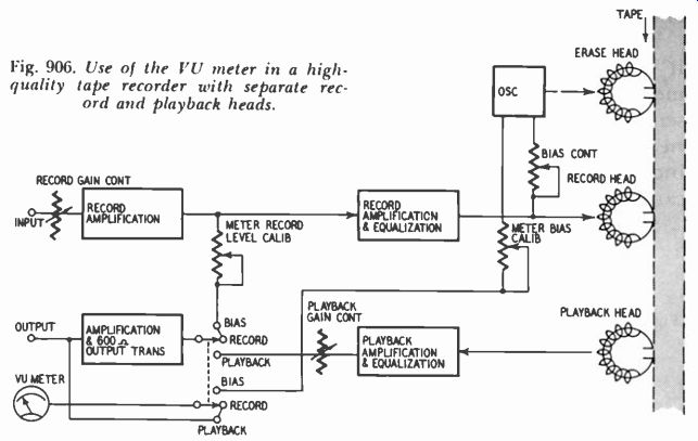
Fig. 906. Use of the YU meter in a high-quality tape recorder with separate
record and playback heads.
If the signal fed into the program line of a radio station is too low, there may be interference from other adjacent audio lines in the studio because of their relatively higher levels. Or the tape playback signal may be too small in view of the amplification capabilities of following audio equipment. Commercial studio equipment generally has at least 10-db reserve gain, but an occasional tape may come along which was recorded at so low a level that the following equipment cannot amplify it to the extent necessary for broadcast or recording purposes. In this case the meter indicates the inordinately low level and the operator can turn up the recorder's playback gain control.
On the other hand, if an excessive amount of signal is developed in tape playback, this may produce crosstalk on other audio lines in the studio. Also, it may cause distortion or un necessary compression in associated line amplifiers, which often do not have level controls. And compression itself generates a certain amount of distortion.
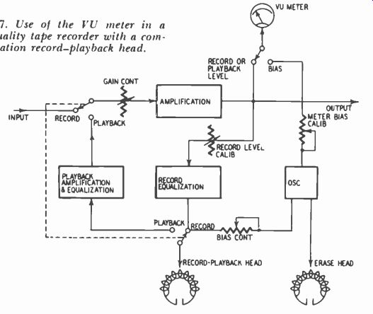
Fig. 907. Use of the VU meter in a high-quality tape recorder with a
combination record-playback head.
Thus it is apparent that being able to meter playback level is a valuable facility. Figs. 906, 907 and 908 show how provision is made for metering playback level in three representative high-quality tape recorders. In Fig. 906, where separate record and playback heads are used, the VU meter is directly across the final output stage, except when measuring bias, and is switched along with this stage between the signal being recorded and the play back signal. In Fig. 907, the same head is used for record and playback. Unless the meter is switched to read bias, it automatically reads record level or playback level, depending upon what mode the machine is in, because all signals go through the common amplification stage to which the meter is connected. Fig. 908, again for a three-head machine, employs a somewhat different setup which requires two switches to be positioned properly to read playback level; the meter switch must be connected to the final output stage, and this in turn must be connected to the early play back stages.
For the majority of home uses, the playback indication is of no importance. Therefore, moderate-price tape recorders permit the record-level indicator to function in playback only by inadvertence or for some purpose other than indicating playback level.
If it does function, there is usually no meaning to the reading.
Some manufacturers whose machines use an electron-ray tube choose to have it remain on in playback and serve as a pilot light.
Others allow the tube to operate only in record; thus it warns that the machine is in the record mode and helps guard against accidental erasure of a tape. For the electron-ray tube to operate only in record, it is necessary simply to supply its B-plus voltage from the same point as for the bias oscillator, which is always shut off in playback.
Drive circuits and requirements
-------------
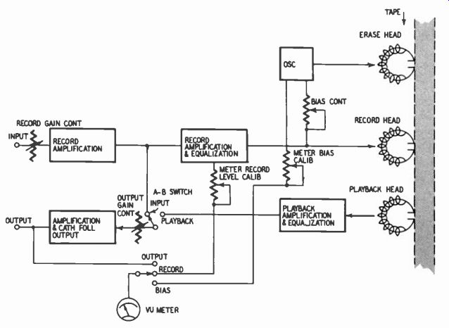
Fig. 908
Each of the basic types of indicator-meter, electron-ray tube and neon lamp-have considerably different requirements as to circuitry and driving power. Therefore, the design of the tape amplifier must carefully take into account the type of indicator that is to be used. It is not feasible to change from one to another without making fairly extensive changes.
VU meter circuitry
A VU meter reads 0 VU when the meter is connected directly (without a 3,600-ohm resistor) across a 600-ohm resistance carrying 1 mw of power. The corresponding drive voltage is 0.774; by Ohm's law, E = VWR = V.001 x 600 =x/0.6 = 0.774 volt. However, the VU meter requires a 3,600-ohm series resistor to limit distortion due to nonlinear loading, and this necessitates a signal 4 db above 1 mw, namely 2.5 mw, to produce a 0-VU reading. The corresponding voltage is V.0025 X 600 = V1.5 = 1.23.
This, then, is the required driving voltage from a source having 600 ohms nominal impedance.
However, if a high-impedance source is used, say upward of 10,000 ohms, the VU meter would produce serious distortion due to loading, even with a 3,600-ohm external resistor. Furthermore, a considerably greater driving voltage would be required because of the loading effect of the meter circuit. Although the source may originally have presented 1.23 volts, the total impedance of the VU meter circuit is only 7,500 ohms (VU meter internal resistance of 3,900 ohms plus external 3,600-ohm resistor) and the loading effect is such that 1.23 volts is no longer available to drive the meter.
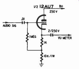
Fig. 909. Cathode follower suitable for driving a VU meter.
The proper way of connecting a VU meter is to place it (in series with a 3,600-ohm resistor) directly across a nominal 600-ohm line, as shown in Fig. 903. Thus many professional tape recorders have a 600-ohm output transformer, as represented in Fig. 906. The amplifier stage preceding this transformer may be connected to the record section so that the VU meter serves as a record-level indicator or to the tape playback section so that the VU meter serves as a playback indicator.
Fig. 908 represents a tape recorder with a cathode-follower out put. The VU meter may be connected across this output to read playback level or, depending upon the position of the A-B switch for comparing incoming with playback signal, the meter can measure the incoming signal. However, the meter properly serves as a record-level indicator when switched to its record position, where it is connected to a calibrated signal voltage from the record stage.
Occasionally one encounters a circuit in which the VU meter is not placed directly across the output but instead is driven by a special cathode follower. (Refer to Fig. 909.) The advantage is that the VU meter therefore does not load down the audio playback signal. Though specifications call for distortion produced by the VU meter to be no more than 0.2% harmonic, even this amount may be considered too much.
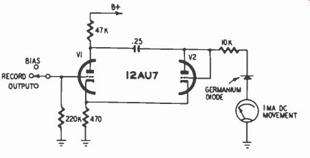
Fig. 910. Vtvm type record-level indicator.
Volume-indicator circuitry
The volume indicator is driven to full scale, ordinarily, by a source impedance of 500 ohms carrying 6 mw of power. This translates into a voltage requirement of 1.73 compared with 1.23 for the VU meter (using an external 3,600-ohm resistor). A 500 ohm output transformer or a cathode follower provides a suitable driving source. The volume indicator generally has an internal resistance of 5,000 ohms and is intended to be placed directly across an audio line without the use of a series resistor.
Vtvm type indicator circuit
This record-level indicator employs a much less sensitive movement than the VU meter, generally a 0-1 milliammeter. The required driving current is usually obtained by vacuum-tube amplification. Rectification of the audio signal is obtained through the use of a vacuum-tube diode, germanium diode or copper oxide rectifier.
Fig. 910 shows a typical circuit. V1 amplifies the signal being measured. The germanium diode serves as a rectifier for the meter. V2 is connected as a diode (plate and grid tied together) and provides a shunt on positive halves of the cycle, thereby charging the 0.25-pf coupling capacitor. On negative half-cycles, the signal voltage at the plate of V1 is in series with the voltage charge on the capacitor, resulting in the sum of the positive and negative signal swings being impressed on the meter. This is. in effect, a voltage-doubler circuit, but it also behaves as a full-wave rectifier.
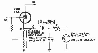
Fig. 911. Circuit of a peak-reading meter.
The cathode of V2 is across the cathode resistor of V1, and therefore has a positive voltage. Consequently, V2 does not con duct until the signal at the plate of V2 goes positive by an amount in excess of the positive voltage at the cathode. This permits V2 to behave somewhat in the same manner as the crystal diode which has a high forward resistance and therefore passes little current at low signal levels. The 10.000-ohm resistor is chosen to calibrate the meter.
Peak-reading meter
Fig. 911 shows a representative circuit for driving a 200-ua movement so as to read peaks. The signal is obtained from a cathode follower assumed to have 300 ohms impedance. The rectifier is a germanium diode having 200 ohms forward resistance. Thus, capacitor C2 is charged to 0.636 of its maximum value in a length of time determined by the time constant C2 (R1 R2). For the values in Fig. 911, the time constant in microseconds is 0.1 (300 + 200) = 50 u-sec. This is a short enough period for C2 to be charged by any waveform in the audio range. C2 cannot discharge through the rectifier. Instead, it discharges to 0.364 of its maximum value through the meter and R3 (a total resistance of 5,000 ohms) in a period determined by the time constant C2 (R3 + R4).
Multiplying 5,000 by 0.1 yields a discharge time of 500 usec. This is slow enough so that most peak voltages impressed on C2 have time to produce an essentially proportional swing of the meter.
It may be noted that C2 cannot charge quite to the incoming voltage. R1 R2 act as a voltage divider with R3 + R4. There fore the voltage impressed on C2 is proportional to 5,000/5,000 500, or 91% of the voltage supplied by the cathode follower.
This represents a signal loss of less than 1 db.
Drive requirements depend upon the sensitivity of the meter.
Although a 200-pa movement is shown in Fig. 911, more or less sensitive meters could be used, depending upon the amount of signal available. Fig. 911 assumes that 1.1 volts is available. This...
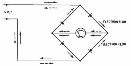
Fig. 912. Full-wave rectifier.
...is sufficient, after voltage division, to drive the 200-pa meter to full scale. The meter resistance R4 represents 300 ohms out of a total of 5,500, including R1, R2, R3, R4. Consequently, 300/ 5,500, or approximately 5.5% of the voltage available at the cathode follower is impressed across the meter. And 5.5% of 1.1 volts is about 0.06. To drive a 200-pa movement having 300 ohms resistance, the required voltage is 0.0002 X 300 = 0.06 volt.
In view of the relatively small load resistance presented to the negative half of the signal by C1, the rectifier and C2, the peak-reading meter circuit (as illustrated in Fig. 911) should not be connected directly across the output of a tape recorder. This might cause clipping of alternate signal peaks, thereby producing distortion. Instead, it should be driven by its own cathode follower.
Full-wave vs. half-wave rectifiers
Before considering the circuitry of electronic indicators, it is advisable to pause briefly to consider the question of full-wave vs. half-wave meter rectifiers.
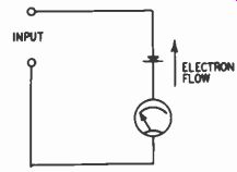
Fig. 913. Half-wave rectifier.
The VU meter contains a full-wave rectifier (Fig. 912). As shown by the arrows, electrons flow through the meter from right to left on both the negative and positive halves of the input signal. The solid arrows represent negative and the dashed arrows positive polarity at the upper input terminal.
A simpler form of rectifier, the half-wave type, is shown in Fig. 913. Although less expensive, the half-wave rectifier has two disadvantages. First, since it passes only half the audio signal (either the positive or negative half of the waveform), the rectifier delivers only half as much current to the meter. This loss in sensitivity may require either a more sensitive meter or more amplification prior to the rectifier. Second, half-wave rectification may not provide a true indication of level because speech and music waveforms are not symmetrical. As a result, the meter driven by a half-wave rectifier may somewhat understate or over state record or playback level.
The electron-ray tube circuit Although several other magic-eye tubes are suitable as record-level indicators, the 6E5 is most commonly used because of its low cost and relatively modest drive requirements.
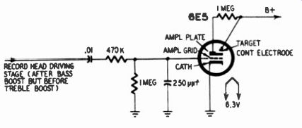
Fig. 914. Use of an electron-ray tube as a record-level indicator. (Pentron
TR4)
Fig. 914 shows the 6E5 in a typical circuit. The electron stream flowing from the cathode to the target produces a circular fluorescent pattern. A ray-control electrode deflects part of the electron stream so as to form a shadow, as shown in Fig. 905. This deflection electrode is connected to the plate of a triode amplifier within the same tube envelope. When the plate of the amplifier goes positive due to a negative voltage on the grid, its deflecting ability decreases and the shadow partly or completely disappears.
The 1-megohm and 470,000-ohm resistors in Fig. 914 form a voltage divider which provides the correct amount of signal to the 6E5 grid so that full closure of the eye corresponds to maximum permissible recording level. Between-6 and-8.5 volts are required at the grid to close the eye. Signal voltages well in excess of this amount are readily found in the tape amplifier when it is in the record mode.
In the circuit of Fig. 914, the electron-ray tube is constantly and rapidly flickering and therefore somewhat difficult to inter pret. To provide a "floating action" which permits the eye to maintain its shadow size for a suitable fraction of a second, a circuit along the lines of Fig. 915 is often employed.
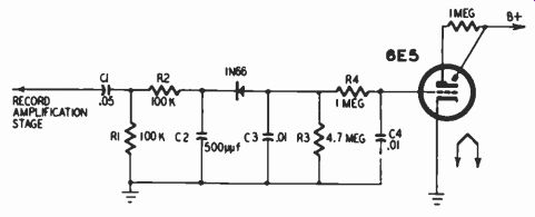
Fig. 915. Use of an electron-ray tube as a record-level indicator with "floating
action." (Viking RP6I tape amplifier).
This circuit is basically similar to that of Fig. 911. The time constant of R2 and C3 permits C3 to be charged on negative signals through the 1N66 in about 1/1000 second. But C3 must discharge through R3 because the 1N66 has a very high back resistance. The time constant of C3 and R3 is about 1/20 second, which means it takes that long for C3 to discharge. Thus the magic-eye reading is maintained for a period long enough so that the human eye can follow. Further smoothing action is provided by R4 and C4, which filter fluctuations above 16 hz; in other words, they tend to maintain a discharge period of about 1/16 second.
The 1N66 germanium diode is used in Fig. 915 because it has a very high back resistance, that is, high compared with a 4.7 megohm resistor. A more familiar type such as the 1N34 has considerably lower back resistance and therefore would not be suitable. Some tape recorders, to obtain the necessary back resistance, use a vacuum-tube diode. Often a spare half of a dual triode is used, the plate and grid being tied to form a diode.
The neon lamp
Where a neon lamp is decided upon as a record-level indicator, the NE-51 is commonly used. Approximately 90 volts are required to fire the gas in the lamp. The lamp continues to glow until the voltage drops to about 60, so that there is somewhat of a built-in floating action. In certain tape recorders there is a high enough signal voltage available in the record amplifier to fire the NE-51. In other cases, the difference between the available signal voltage and the firing voltage is made up by applying about…
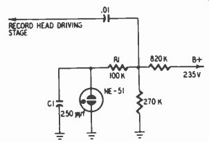
Fig. 916. Use of a neon lamp as a record-level indicator. (Pentron CT1)
… 40 or 50 volts of B plus to the lamp so that it is necessary to obtain an audio signal of only 40 or 50 volts to actuate the lamp. Fig. 916 illustrates the latter method of driving the indicator.
The 820,000- and 270,000-ohm resistors form a voltage divider which applies the proper amount of B plus (about 50 volts) to the NE-51. Positive halves of the audio signal, obtained from the stage that drives the record head, raise the voltage across the NE-51 to about 90.
In some tape recorders there is sufficient amplification of the audio signal to supply the 90 volts required to fire the NE-51.
The reader may well wonder how it happens that audio voltages reach such a level. The answer has special interest because it is a good example of the interdependence of design elements.
Gain is expensive, and in a moderate-price tape recorder a high-inductance record-playback head is especially desirable because of its relatively great output in playback. On the other hand, when this head is used for recording, its high inductance requires the use of a large constant-current resistor in series with the head to prevent discrimination against treble frequencies. Resistors as large as 200,000 ohms are not uncommon and, to provide enough current to the record head, they necessitate a relatively high record voltage, sometimes great enough to ignite a neon lamp Moderate-price recorders usually contain their own power amplifier and speaker for playback. In some circuits the power output stage, typically employing 6AQ5 or 6V6 tubes, is switched in the record mode to drive the record head (a dummy load resistor is some times connected across the secondary of the output transformer to replace the speaker, thereby protecting the transformer). The required voltage for driving the record head is available at the plate of the power output tube. Where the power amplifier uses push-pull output, the voltage is taken from the plate of one of the tubes. This voltage may be sufficient to actuate the neon lamp without the aid of a biasing II-plus voltage.
Commercial-grade neon lamps do not all light at the same voltage. Consequently, when replacing a worn-out lamp, the ac curacy of the record-level indication may change by several db.
When recording at high levels, a further rise of 2 or 3 db can seriously increase distortion.
Although the neon lamp, on the whole, serves nicely enough to show the record level corresponding to maximum permissible distortion, it does not indicate whether recording is at too low a level. Even the electron-ray tube performs this service for the operator, although not as well as the meter type of indicator.
Therefore a number of tape recorders employ a second ("normal") neon lamp, which fires at a lower signal level, say about 6 db less. The user sets record level so as to lamp as much of the time as possible without causing the "overload" lamp to light unduly.
Fig. 917 shows a special circuit employing two NE-51 lamps.
In this case no dc biasing voltage is needed. The record head and the lamps are driven by a 6AQ5, which serves as a power amplifier in playback and amplifies both the audio and the supersonic bias signals during record. The 5-70 uuf capacitors regulate the amount of bias signal applied to the lamps. This together with the audio signal lights them.
Loading distortion
Specifically in the case of the VU meter, the record-level indicator should not load down the signal being measured. Unless the impedance of the indicator circuit is considerably higher than the impedance of the signal source, the indicator load will cause the signal voltage to decrease, possibly to the extent where there is insufficient voltage to drive the indicator.
The VU meter, the volume indicator and various other record-level meters employ copper oxide or crystal rectifiers which have nonlinear characteristics. The impedance of these rectifiers varies with signal polarity and instantaneous voltage. Taking the V1I meter as an example, assume that as a result of varying rectifier impedance the meter circuit looks like a 7,500-ohm resistance fluctuating over a 10% range. If a 10% change in load resistance has a significant effect on the voltage of the signal source, which is the case if the load impedance is less than about 10 times the source impedance, the non-constant load resistance will cause appreciable distortion.
In other words, the signal voltage is being continuously modified by the 7,500-ohm varying load resistance.
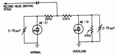
Fig. 917. Use of dual neon lamps as a record-level indicator. (Wilcox-Gay
4A10)
Such distortion may be negligible, less than 0.2% harmonic in the case of a VU meter connected in series with a 3,600-ohm resistor across a 600-ohm line. Ironically, the greatest distortion occurs at low signal levels, where the copper oxide and crystal rectifiers exhibit the greatest amounts of nonlinearity. In some circuits the IM distortion may be several percent at low levels.
Similarly, electron-ray circuits can produce loading distortion if proper measures are not taken. When the signal applied to the grid of the electron-ray tube goes positive, there is conduction between cathode and grid since the grid has no negative bias on it, the cathode being at ground (Fig. 914). This is equivalent to a low resistance load on the signal source during positive swings.
When the signal goes negative, however, the effective cathode-grid resistance becomes infinite again. To limit distortion, a series resistor is used between the signal source and the electron-ray grid. It serves to keep the load resistance from going below a certain minimum and thereby prevents appreciable loading of the source. In Fig. 914 this series resistor has a value of 470,000 ohms.
Similarly, in the case of a neon lamp, its reduction in resistance when fired can load down the source; the change is from infinite resistance to about 100,000 ohms. Therefore a series resistor is employed between the audio source and the neon lamp, as shown in Figs. 916 and 917 to keep the load from varying excessively.
Calibration of record-level indicator
At high record levels moderate increases in signal applied to the tape can produce relatively great increases in distortion.
When the record level is high enough to produce about 10% IM distortion (acceptable for brief passages), an increase of 5 db in level can raise IM distortion above 30%. Thus, proper calibration of the record-level indicator is necessary. The indicator must be calibrated so that it gives a designated reading at the signal level corresponding to maximum permissible distortion. On the other hand, if the indicator is mis-calibrated so as to indicate "overload" at a lower level, then the recording will have an unnecessarily low signal-to-noise ratio.
Professional recorders as a rule incorporate means for adjusting the record-level indication, while semi-professional ones occasionally do so too. Moderate-price recorders very seldom do.
Instead they generally use fixed voltage dividers to regulate the indication level.
Fig. 906 shows the means provided by a typical professional tape recorder for adjusting the record-level indication. The signal going to the output stage and VU meter comes through a potentiometer which is adjusted so that the output level and meter reading correspond to a record level resulting in a specified amount of distortion, usually 2 or 3% harmonic. This potentiometer is adjusted at the factory. The user equipped with the necessary test instruments or a test tape can also adjust it. Figs. 907 and 908 show how other professional recorders provide for such calibration. In the case of Fig. 907, it is the amount of signal going to the record head rather than the signal to the VU meter which is adjusted.
Fig. 917 represents one of the rare instances in which a moderate-price recorder permits ready adjustment of the signal level at which distortion is indicated. The trimmer capacitors act as voltage dividers in series with the 330,000-ohm resistors at the bias frequency. The neon lamps are actuated not only by the audio signals but also by the bias signal, the amount of the latter being determined by the trimmer setting. The audio voltages at which the lamps should light are first determined and then just enough bias voltage is added by means of the trimmers to actually fire the lamps.
The electron-ray tube, neon lamp and peak-reading meter all read signal peaks and thus truly indicate when the record level is such as to produce objectionable distortion. However, the VU meter and other meter type indicators read only average rectified signal level, whereas it is the peak level that determines the maximum amount of distortion.
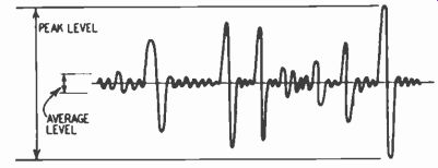
Fig. 918. Typical musical waveform as seen on an oscilloscope.
If the relation between peak level and rectified average level were constant, there would be no problem. Thus, a sine wave has a rectified average level about 4 db below its peak level, and, if only steady sine waves were being recorded, the VU meter could be adjusted to read 0 VU on the basis of a sine-wave input producing, say, 2% harmonic distortion. But typical program material has many transients which exceed the average level not by 4 db but by as much as 20 db (Fig. 918). These relatively tremendous peaks, though brief, can cause very severe distortion.
Consequently the calibration of a VU meter (or other average-reading meter) should be set to make allowance for the difference between average level indication and actual peak level. In many, though not all, professional tape recorders, some 6-10-db allowance is made for this. In calibrating the VU meter, it is set to read 0 VU for a sine-wave signal (usually 400 hz) 6 to 10 db lower than that which produces maximum allowable harmonic distortion.
Even though the VU meter (or other meter) is calibrated with a reserve of this sort, the recordist cannot blithely adjust record level so that the pointer swings to a maximum of 0 VU.
He must still exercise judgment and bring experience to bear.
Different audio sources have different relationships between peak and average levels. Thus a maximum meter reading of 0 VU can result in over-recording in one case, while in another it may reflect an unnecessarily low recording level and hence too low a signal-to-noise ratio. For example, some organ music might have a ratio between peak and average levels not much greater than 5 db or so, whereas brass and percussion instruments might have ratios as high as 20 db. Therefore, in setting record level on the basis of the meter reading, the recordist must make allowance for the type of material being recorded.
Moreover, in some types of program material a given amount of distortion is less objectionable than in others. For example, a relatively large amount of distortion can usually be tolerated in reproduction of speech. At the same time, speech often has relatively large transients. Thus, the need to allow for transients is more or less offset by the greater tolerable distortion. On the other hand, in different circumstances there may not be such an offsetting effect, but instead a need for all the greater caution on the recordist's part.
Finally, it is important to decide whether it is 1%, 2% or 3% harmonic distortion that is the maximum allowable amount.
These relatively innocuous differences in harmonic distortion can mean vast differences in the amount of IM distortion. Thus, when harmonic distortion is at 1%, IM may be at 10%, which is acceptable, whereas IM may exceed 30% when harmonic distortion is 3%.
Circuit location In many tape machines, including professional ones, the record-level indicator is connected to a point in the record amplifier where the audio signal has not yet been subjected to treble equalization, which ranges from a minimum of about 10 db to up ward of 20 db at 7.5 ips. It may therefore be questioned whether an indicator so connected satisfactorily warns against distortion in the treble range. Essentially, the answer is that it does. Record treble boost largely affects the spectrum above 3,000 hz, and in this area the decline of audio energy with rising frequency tends to offset the record boost. Moreover, for the same amount of distortion, somewhat greater signal levels can be applied to the tape at high frequencies than at low ones.
Of course, it is not certain that the decline in energy at the high end always compensates the record treble boost. To be safe, it is desirable to connect the record-level indicator to a point where treble equalization has been fully applied. Therefore some tape recorders, like the one illustrated in Fig. 908, connect the meter in this fashion.
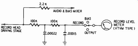
Fig. 919. Filtering network to eliminate bias pickup by record level
meter. (Concertone TWA amplifier)
On the other hand, many manufacturers, including some who make top-quality machines, have chosen to locate their indicators prior to record treble boost for several reasons: (1) Feeding the meter from a point preceding high-frequency equalization achieves better isolation between the level indicator and the record head, helping in large measure to prevent bias current from producing an unwanted reading on the indicator. (2) Where a meter is used, if high-amplitude peaks of treble frequencies were fed to it after undergoing a substantial amount of boost, the meter might be damaged, particularly if the record level was accidentally set much too high. (3) Where a meter can be used to compare playback level with the incoming signal, proper comparison between the two would not result if the incoming signal were metered after treble emphasis but the playback signal were metered flat. On the other hand, as illustrated in Fig. 908, it is possible to circumvent this problem by a switching arrangement which enables the meter to measure the incoming signal either prior to or after equalization, the latter for purposes of record-level indication.
Whereas Fig. 908 conforms to the philosophy of metering record level after treble equalization, Figs. 906 and 907, reflect the opposite practice.
Bias pickup
Bias pickup may cause a meter, electron-ray tube or neon lamp to give an erroneous indication of record level. Bias current is of much greater magnitude than peak audio signals and its relatively high frequency range of 30,000 to 100,000 hz causes it to display the radiation characteristics of radio frequencies; hence the chances of stray pickup are considerable.
Tape recorders must take measures to eliminate such pickup.
Fig. 919 shows a two-stage filtering network used to prevent bias current from significantly affecting a meter indicator. This fairly elaborate precaution is required because the meter circuit is connected through a 2,200-ohm resistor to the stage where the audio and bias currents are mixed before going to the record head. In other recorders, however, where the indicator picks up the record signal at an earlier stage, little or sometimes no filtering is necessary. In other words, there is least chance of bias pickup at points in the record amplifier farthest removed from the record head.
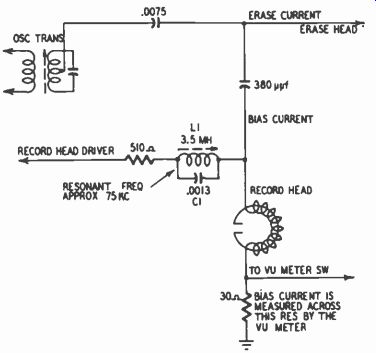
Fig. 920. Resonant trap for preventing bias cur rent leakage. (Presto
SR-27)
Figs. 914, 915 and 916 illustrate precautions taken against bias pickup in the case of electron-ray and neon-lamp indicators. In Fig. 914, the 250-ppf capacitor between grid and ground has sufficiently low reactance at the bias frequency to act essentially as a short to ground. However, this capacitor in conjunction with the 470,000-ohm and 1-megohm resistors also appreciably reduces audio frequencies above approximately 2,000 hz. On the other hand, most of the signal represents frequencies below 2,000 hz.
In Fig. 915, the bias frequency is filtered by R2-C2. The time constant of these components also results in a significant reduction of audio frequencies above approximately 3,000 hz. How ever, virtually all the fundamental frequencies and most of the audio energy occur below 3,000 hz.
In Fig. 916, which illustrates a neon-lamp indicator, bias filtering is accomplished by R1-C1. Its cutoff frequency is such that only audio frequencies above 6,400 hz are appreciably shunted to ground.
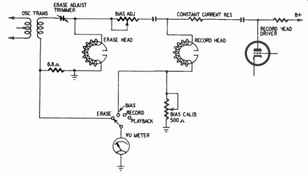
Fig. 921. Typical bias and erase metering circuit.
Fig. 920 shows an entirely different arrangement for keeping bias current away from the record-level indicator (a VU meter) and other parts of the record amplifier. L1 and C1 constitute a parallel-resonant trap with a very high impedance at the bias frequency and a relatively low impedance (due to LI) at audio frequencies. Audio current can flow from the record amplifier through the trap to the record head. But bias current cannot flow to a significant extent in the reverse direction.
Metering bias and erase currents
Virtually every tape recorder which incorporates a VU or other type meter also uses it to measure the amount of bias current going to the record head (Figs. 906, 907 and 908). This is of fundamental importance because bias current affects distortion and frequency response and has a fairly critical optimum value.
It is a decided asset to be able to check whenever desired whether bias is at a level previously determined to be correct. Such factors as aging of the oscillator or rectifier tubes, line voltage and warmup time can affect the bias level.
Unfortunately meter circuits are the only ones which make possible reliable readings at the high bias frequencies that are used-ranging upward of 30,000 hz. Neither the electron-ray tube nor the neon lamp can be calibrated with sufficient accuracy to provide useful readings of bias current.
The most commonly used technique for the measurement of bias current is to insert a small resistor between ground and the record head's ground lead (Fig. 920), and to measure the voltage across this resistor. The value of the resistor is chosen so that enough voltage is developed across it by the proper bias current to produce a designated meter reading. Often an adjustable resistor is used for ready calibration.
Some of the top-flight professional tape recorders also provide for metering the oscillator current through the erase head, using a similar technique.
Fig. 921 shows a typical circuit for metering bias and erase current.