AMAZON multi-meters discounts AMAZON oscilloscope discounts
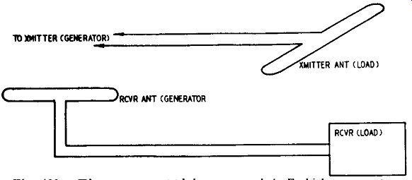
Fig. 401. The energy supplying source is called the generator.
The receiver of the energy is called the load. If the coupling between two electrical circuits is to be of maxi mum efficiency, the impedance of the source of power (generator) should be equal to the impedance of the load. In the case of a signal generator feeding the input to a TV receiver, therefore, the impedance of the signal generator should be equal to the impedance of the transmission line and the impedance of the line should be equal to the input impedance of the tuner in the TV receiver. The same rule applies, of course, if we are using an antenna instead of a signal generator to supply the energy to the front end of the TV receiver. (The source that supplies the power, whether it is a TV transmitter, a receiving antenna or a generator, is always considered the generator or source-of-supply end; the receiver or transmitting antenna is always expressed as the load end.) See Fig. 401.

Fig. 402. Circuit diagram of a balanced probe. The circuit resembles a full-wave
rectifier.
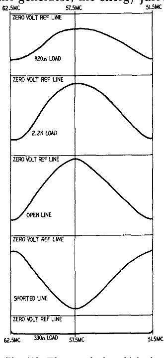
Fig. 403. The margin by which the standing wave pattern fails to con tact
the reference line measures the loss in the transmission line.
If the two impedances are not equal, all the energy supplied by the generator will not be absorbed by the load and some of it will be reflected back through the connecting line to the generator.
In the meantime the generator is continually putting out energy, but, because of the time required for this energy to travel to the load and back to the generator, the energy just coming out of the generator will be out of phase (time) with the energy that has already been reflected back from the load.
In television circuits, this is very undesirable because this reflected power will cancel some of the signal coming out of the antenna into the transmission line, making the signal weaker. As a matter of fact, if this unwanted reflected signal is strong enough, it may even attenuate the signal to a point where it is completely useless, especially in fringe areas where the signal is not too strong.
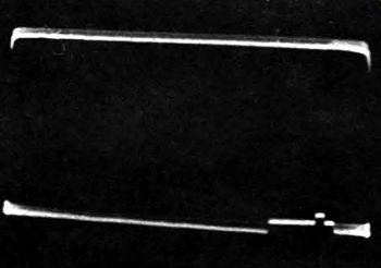
Fig. 404. The crystal probe may rectify the incoming video signal when the
impedance match of the line is checked with high field strength present from
a local TV station. In the example shown above, the video signal appears chiefly
as a "stripped" vertical pulse in the impedance pattern.
Need for balanced probe
To check mismatches in impedances, the balanced probe is invaluable. By following a simple procedure the technician can use the probe to determine whether the generator, line or load is at fault. Of course we have to assume, if the tests are to be accurate, that all of the instruments used have themselves a fairly high degree of accuracy. If they do not, we should know their error so that proper compensation can be made for arriving at the correct results.
A balanced crystal probe (or two single-ended conventional crystal probes) can be used to check a lead-in for flatness or impedance match. A generalized circuit of a balanced crystal probe is seen in Fig. 402. Typical patterns and the conditions responsible for the observed standing-wave ratios are shown in Fig. 403.
To understand the operation of a double-ended probe. note that the two diodes do not conduct simultaneously. As far as the instantaneous lead-in voltages are concerned, when the input signal to one diode is positive, the input signal to the other is negative. These polarities alternate at the carrier frequency and the diodes conduct alternately.
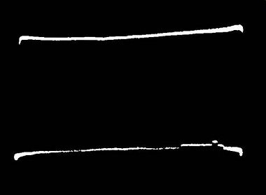
Fig. 405. Curvature in the zero-volt reference line, sometimes noted during
impedance checks of lead-ins and antennas, or front ends of TV receivers, is
cawed by 60-cycle pickup in the balanced crystal probe. Grounds should all
be returned to a common point, and thence to a cold-water pipe. Ground all
instrument cases.
Standing-wave patterns are sometimes interfered with by TV station signals or 60-cycle hum voltage, as shown in Figs. 404 and 405. Unless the operator recognizes the sources of such distortion, he may be at a loss to interpret the pattern which he has obtained.
In Fig. 402, the scope and the sweep generator are located at opposite ends of the transmission line. That is, the sweep generator is located at the left-hand end of the lead, and the scope is connected (through the crystal probe) at the right-hand end. In this test, a pair of 150-ohm resistors are connected in series to provide a 300-ohm load with a center tap. The center tap is required in this test to provide a d.c. return path for the balanced probe.
If the characteristic impedance of the line is 300 ohms, the 300-ohm load will cause a flat trace to appear on the scope screen, as shown at the top of the photograph in Fig. 404. If the characteristic impedance of the line is not 300 ohms, the 300-ohm load will cause the trace to depart from flatness. Fig. 403 shows the behavior of a section of 300-ohm ribbon line when swept with various values of load resistance. The operator will understand that a length of lead 25 or 30 feet long should be used in this test, so that appreciable standing waves can be developed at representative TV signal frequencies. Otherwise the scope must have very high gain to obtain satisfactory deflection.
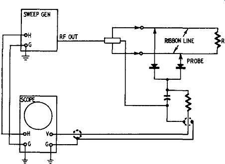
Fig. 406. Horizontal sweep leads shortened. Scope is at generator end of line.
Several other practical considerations must be observed. Since the scope and the sweep generator are located at opposite ends of the line which is being tested, there may be a problem of obtaining a horizontal-sweep voltage from the generator for the scope.
Although some service scopes provide a phasable horizontal-sweep voltage which is built into the scope, many service scopes do not have this built-in sweep facility, but rely upon the phasable, horizontal-sweep voltage which is built into the sweep generator. In that case, test leads are run from the generator to the scope to provide such a voltage.
Since these test leads would have to be 25 or 30 feet long, other test setups may be found more convenient when using a scope without a built-in horizontal phasable sweep. The probe and scope can be connected at the generator end of the line, if de sired, as shown in Fig. 406. In this case, the generator has an r.f.
output cable which is terminated in a center-tapped load. This center point is connected to the ground system of the test setup, as shown; the load resistor R then does not need to be center tapped, and the scope is conveniently swept from the generator, as indicated by the leads between them in Fig. 406. This arrangement can be applied conveniently, especially when the load R may represent a remote point such as an antenna whose match to the lead-in is to be tested.
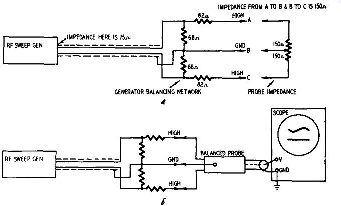
Fig. 407-a,-b. The balanced probe has a 300 ohm input, 75 ohm output: Since
sweep generators have a 75 ohm output, a generator balancing net work is needed
to match the generator to the probe. This is shown in a, above. The technique
for connecting the scope, balanced probe, matching network, and sweep generator
is shown in the lower illustration, b.
Zero-volt reference line
These tests mean little unless a zero-volt reference line is avail able in the pattern. Since generators have unbalanced output, a resistive network is used to produce a balanced condition, as shown in Fig. 407-a,-b. The probe is connected to the balanced output of the signal generator. If the generator is working properly and its output is linear (constant throughout its sweeping range), a straight line will appear across the scope screen. This test would mean very little if a zero-volt reference line was not visible on the scope screen. This zero-volt reference line makes it possible to determine the ratio of maximum to minimum because the zero volt reference line will appear as a straight line and the resultant output of the sweep generator will appear as another line vertically displaced from the reference line on the screen (Fig. 408). If the sweep generator used is provided with internal blanking (zero reference), the zero-volt reference line is immediately avail able when the blanking control on the sweep generator is turned to the blanking-on position. Caution: it is important to mention that if misleading curves on the scope screen are to be avoided, the phasing control on the sweep generator must be adjusted so the trace and retrace lines on the scope screen coincide before the blanking control is switched to the blanking-on position.
If the sweep generator does not have an internal blanking provision, a d.c. scope may be used to provide the zero-volt reference line. This is accomplished by positioning the scope trace with zero-signal input and marking this line with a grease pencil.
This line may then be used as a zero-vo1t reference line, provided that the positioning controls on the scope are not touched. It is important to have the d.c. amplifier balanced; otherwise the zero reference line may change with gain.
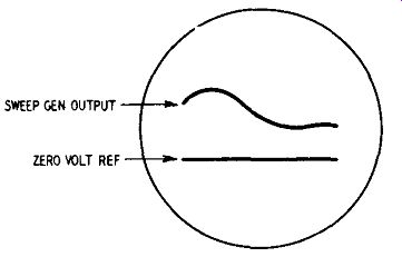
Fig. 408. Sweep generator output and zero volt reference line.
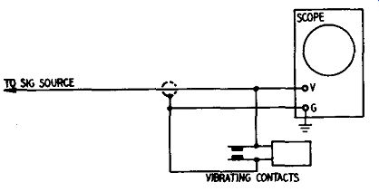
Fig. 409. Vibrating contacts intermittently short the vertical input of the
scope.
Obtaining the reference line
There are two ways of obtaining a zero-volt reference line. The most convenient one is to use a sweep generator in which the return trace is convened automatically into a zero-volt reference. This is done by providing a built-in source of square-wave bias to the sweep oscillator in the generator. If the technician must use a sweep generator which does not provide a zero-volt reference line in the pattern, any arrangement which rapidly shorts and un-shorts the vertical-input terminals of the scope will serve the same purpose, as shown in Fig. 409. The rate of vibration should be considerably greater than 60 cycles, but may be any convenient arbitrary rate. The vibrating contacts operate to make the input signal fall to zero many times during the progress of the trace, thus making the zero-volt reference level apparent as a dashed line. The average constructor will usually have little trouble devising a vibrator, if one is needed. The vibrating frequency does not have to be stable, but the contacts must be completely independent of the magnetic circuit of the vibrating element.
The generator characteristic may be linear or nonlinear. If the line on the scope screen representing the generator output is nonlinear (Fig. 408), we can assume that the generator output is not linear. For any measurement purpose, the degree of deviation from that shape will indicate the degree of mismatch in the tests.
In order to make use of this knowledge of the output characteristics of the sweep generator, the technician must trace this characteristic output curve on the scope screen in grease pencil (China marking crayon) and note its position relative to the zero-volt reference line. The technician must first determine this characteristic so he can apply a correction, if one is needed. To make the matter clearer, consider the case in which the length of line shown in Fig. 406 is reduced to zero. No effects of standing waves are then apparent in the pattern, because they are absent. The trace should then be reasonably flat.
Consider, however, the cases shown in Fig. 410, in which the generator characteristics are not entirely flat. Such instances can arise in practice, due to high harmonics in the generator output combined with probe resonances, for example. In other cases, the fundamental voltage from the generator may vary somewhat.
In any case, a correction must be made.
Testing transmission lines Now that the zero-volt reference line and the characteristics of the sweep generator have been established, the technician is pre pared to put this setup through its paces. As discussed in previous paragraphs, the energy not absorbed by the load will be reflected to the generator. Further, because of the time lost traveling through the transmission line, it will be out of phase (time) with the signal just coming out of the generator. The result will be a disturbance of the wave shape and/or phase (time) of the signal at the generator terminal. The degree of disturbance will be determined by the amount of energy reflected from the load (degree of mismatch).
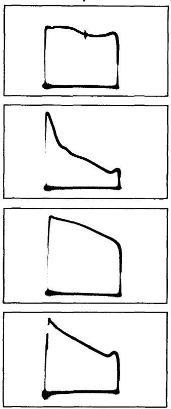
Fig. 410. When an unsuitable demodulator probe is used to test the output
from a sweep-frequency oscillator, or when the instrument is operating incorrectly,
or if test conditions are unsuitable, typical patterns such as these will be
observed as the instrument is tuned through its range.
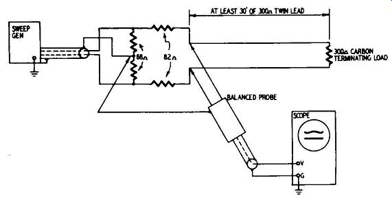
Fig. 411. Technique for testing impedance matching of transmission line.
A resistive network is used to convert the sweep signal generator from u,1 balanced to balanced output.
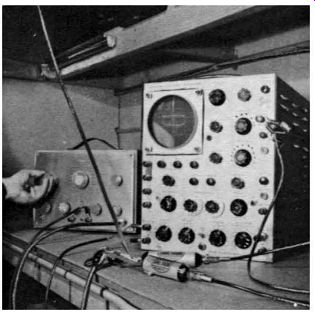
Fig. 412. Photo of test setup utilizing dual crystal probes instead of a balanced
probe.
To check the impedance of a transmission line, connect the balanced probe, the sweep generator, the scope and the length of transmission line (20 to 30 feet) as shown in Fig. 411. Terminate the far end of the transmission line in a noninductive carbon resistor equal in resistance to the rated characteristic impedance of the transmission line under test. This is ordinarily 300 ohms.
If the actual characteristic impedance of the transmission line is equal to its rated value, the traces visible on the scope screen (with appropriate vertical-gain adjustments) will coincide with the traces visible on the scope screen when the generator output characteristics are checked (Fig. 408). If the traces do not coincide, the actual impedance of the line is not equal to its rated impedance. When this condition occurs, the actual impedance of the line may be determined by substituting various values of noninductive carbon resistors as a termination for the line until the traces on the scope screen do coincide with those of the generator output characteristics. Under these latter conditions, the value of the terminating resistor will be the value of the actual characteristic impedance of the line in question.
Checking mismatch between transmission line and antenna or TV input
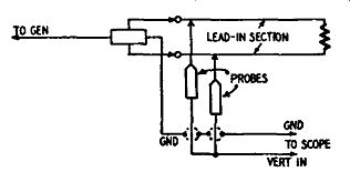
Fig. 413. Diagram of two conventional crystal probes used in balanced tests.
The setup outlined in the previous paragraph may be used to determine the amount of mismatch between a transmission line and either the antenna or TV receiver input circuit.
In this test the instruments are connected as shown in Fig. 411, and either the antenna or TV receiver input circuit is substituted for the line-terminating resistor (load). If a perfect match exists between the line and load, the traces on the scope screen will coincide with those visible on the scope screen when the generator output characteristics were checked (Fig. 408). The degree of mis match will be indicated by the degree of deviation between these two sets of traces.
If the degree of mismatch is large, various types of matching systems such as stubs, baluns or impedance-matching transformers may be inserted between the line and the load until the desired match is indicated by the traces visible on the scope screen. You can construct your own coaxial baluns, if you wish, by following the instructions given beginning on page 73.
If the technician finds that the display is nonlinear (as shown in Fig. 410) when the lead-in length is reduced to zero, the best procedure is to use a grease pencil ( China marking crayon) to indicate the shape of this display on face of the cathode-ray tube.
The penciled curve becomes the reference curve and is the curve that will be obtained when a section of lead-in under test is properly terminated. Any deviations in waveshape from this penciled curve clearly indicate that the section of lead-in is improperly terminated.
If it is desired to use a pair of conventional crystal probes in stead of a special balanced probe, the test setup will appear as shown in Fig. 412. Each of the conventional probes is merely substituting for the diodes shown in Fig. 406. The circuitry used in the dual-probe arrangement is shown in Fig. 413.
Transmission line losses
In Fig. 403, although the line termination is a short or an open circuit, the standing-wave pattern seen on the scope screen when a sweep test is made may not quite touch the zero-volt reference line. The standing-wave pattern will touch that reference line only if there are no losses in the line. When the test frequency is increased, the line losses increase, and the standing-wave pat tern approaches the zero-volt reference line less closely for an open or a shorted termination. The amount by which the pattern fails to reach the zero-volt reference line is a measure of the loss in the line.
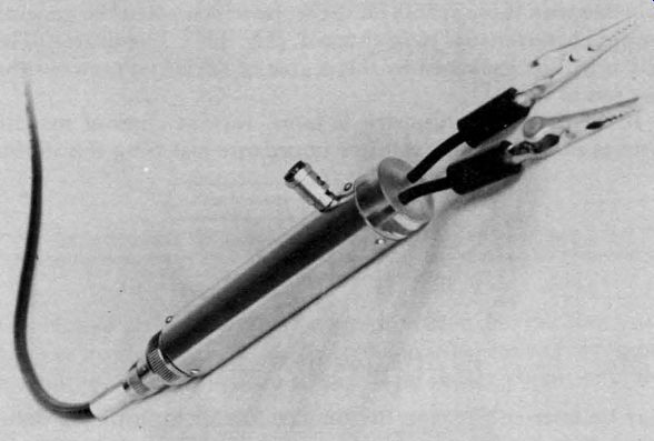
Fig. 414. Photo of balanced probe. The ground connector is fastened to the
probe housing.
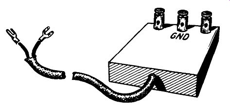
Fig. 415-a. A possible design for a balanced-probe housing.
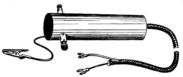
Fig. 415-b. This probe housing follows more conventional design. The two binding
posts should be insulated from the housing.
Construction of a balanced probe
Balanced probes are available commercially. Fig. 414 shows the outside appearance of one such probe. The ingenious technician, however, can construct his own probe from materials he has avail able in his own shop. Figs. 415-a and -b are sketches showing how miscellaneous materials can be adapted regardless of shape to produce satisfactory results. The probe should be carefully shielded to prevent undesired signal pickup.
Despite the outward appearance of the balanced probe, the following basic procedures must be adhered to in its construction if it is to operate satisfactorily: Insulating materials must be of high quality. Short leads are required. Components must be utilized which are designed for use at high frequencies. Resistors should be of noninductive carbon, and all capacitors should be disc ceramic or of a design approved for use at high frequencies. The circuit and component values for a balanced probe are shown in Fig. 416.
The parts used in the construction of the balanced probe are three 270-µµf (approximately) ceramic capacitors, four 120,000 ohm carbon resistors and two 1N34A germanium diodes. The two diodes do not conduct simultaneously and are connected so that when the signal to one diode is positive the signal to the other is negative. This connection keeps the load balanced and, since only one diode is conducting at a time, the resultant output of one will not cancel the output of the other.

Fig. 416. Circuit diagram of a balanced probe using R-C filter. This can easily
be built into either type of housing illustrated in Figs. 415-a or b.
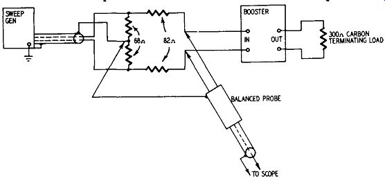
Fig. 417. Setup for using the balanced probe for running tests on TV boosters.
To confine the RF component of the demodulated signal to the probe head, the R-C network shown in Fig. 416 must be utilized. This network allows the low-frequency components to reach the scope, at the same time bypassing the high-frequency components to ground.
Checking gain and response of TV boosters This discussion of the use of the balanced probe should not be concluded without mention of the fact that this instrument also is ideally suited for checking gain, response characteristics and alignment of TV boosters. By connecting booster and instruments as shown in Fig. 417 and applying the balanced probe first to the booster input and then to the booster output, the technician can check the gain. By comparing the amplitudes and waveshapes encountered, he can determine the characteristics of the booster.
This setup may be used to check the efficiency and response characteristics of any coupling device encountered in TV distribution systems, if you merely substitute such device for the booster.

Fig. 418-a.-b. These two illustrations show one technique that can be used
for getting balanced output from a sweep generator. This method does not give
a perfect impedance match.
Coaxial balun
The output of nearly all signal generators used for service work is approximately 72 ohms. The coaxial cable that brings the signal out of the generator is designed to have this same impedance, so that there is no question of impedance mismatching when the cable is connected to the generator. If the TV receiver being serviced has a 72-ohm input, the coaxial cable of the generator can be connected directly to the antenna terminals, and once again all impedance matching requirements will have been satisfied.
However, the majority of TV receivers being manufactured today have a balanced input of 300 ohms. This impedance can be represented by a 300 ohm resistor, center-tapped to ground, as shown at the right in Fig. 418-a. An impedance of this kind is referred to as balanced since the impedances from each side of the input to ground are equal. Signal generators and coaxial cable have unbalanced output because the center-tapping arrangement does not exist with such equipment. We then have the problem of matching an unbalanced 72-ohm signal generator output to balanced 300-ohm TV receiver input.
One of the techniques for doing this is shown in Fig. 418-a. A 72-ohm carbon-type resistor is shunted across the coaxial-cable output. A pair of 1.20-ohm resistors are connected, one to each end of the 72-ohm resistor. The free ends of the 120-ohm resistors now supply the signal output voltage.
Now let us see how this arrangement works when connected to a 300-ohm balanced source, as shown in Fig. 418-b. The two 150 ohm center-tapped resistors could represent the input impedance of a balanced probe or the antenna terminals of a TV receiver.
By examining the circuit we can see that the 72-ohm resistor matches the impedance of the coaxial cable exactly. However, one side of the coaxial cable is grounded and so is the center-tapped input receiving the signal. If you will examine the dashed line in Fig. 418-b you will see that since one side of the generator output cable is connected to ground one side of the balanced load will tend to be of a lower impedance than the other. Thus, our 300 ohm center tapped load is connected to 192 ohms on one side (120 ohms plus 72 ohms) and to 120 ohms on the other side.

Fig. 419. The coaxial balun is simply cable bent back on itself as shown, and
connected to the output cable of the generator. The balun gives a 4:1 impedance
match.
Instead of a resistive network you can make use of a coaxial balun as shown in Fig. 419. A balun is very simple and consists simply of a section of coaxial cable bent back on itself and connected to the signal generator cable. The coaxial balun has fairly good broadband characteristics, and if you cut the balun for the center of each channel in your area, you will have a system that will work. The length of the balun is based on the formula: Length = 492V /f In this formula the length is in feet, f is the frequency in mega cycles, and V is the velocity factor of the cable. For widely used cables such as RG 11 U and RG59U the velocity factor is 0.66.
You can use this formula to find the length of a particular balun you may wish to build, or you can use Table 4 if you prefer.
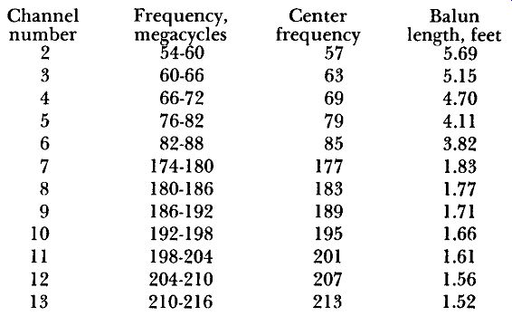
Table 4--LENGTH OF BALUN FOR TELEVISION CHANNELS
AMAZON multi-meters discounts AMAZON oscilloscope discounts