THE feed mechanism controls the available recording time on a disc of given diameter, the direction of cut (outside-in or inside-out), the precision with which the grooves are spaced, and the general convenience with which the mechanical operations can be performed. The mechanism determines, to a great extent, the quality and consistency of recording results.
Two principal types are in present-day use, the swinging arm and the lathe (see Figs. 403, 405, 406, and 407.) They may be distinguished by the location of the lead screw, which is usually underneath the motor board of swinging arm recorders and above the board on lathe mechanisms.

Fig. 401--Lead screw, with spiraling crank.
The lead screw is a threaded rod which is geared to the turntable and mounted parallel to the table, on the mechanism. The cutter mount is engaged with the lead screw, and the revolution of the screw pushes cutter and stylus radially across the disc as recording proceeds. This causes the groove to spiral instead of remaining a perfect circle, as it would if cutter and stylus were not moved across the record. A lead screw is shown in Fig. 401.
Swinging-Arm Mechanisms

Fig. 402-Complete recorder with swinging-arm mechanism; cutter is at
right
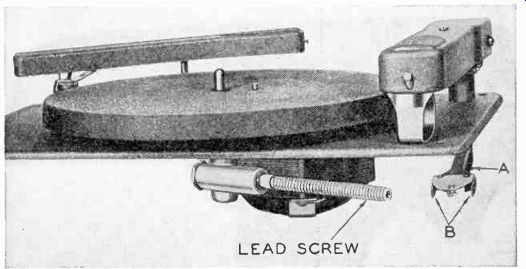
Fig. 403--A swinging-arm recording chassis
Fig. 402 shows a complete recording and playback instrument using a typical swinging-arm mechanism. The arm on the right is quite similar in appearance and function to a pickup arm. A cutter is mounted in its forward end instead of a pickup cartridge.
Fig. 403 shows the feeding method of this type of mechanism. The lead screw (seen under the motor board) is geared to the motor. The cutter arm may be moved over the disc just like a pickup. The arm and rod A are rigidly connected together. When the arm is lifted from its rest and the stylus placed on a blank disc, the 2 flat pieces, B, of metal rest between threads of the lead screw. By ordinary screw action, the turning of the lead screw forces B along the length of the screw.
With B go rod A and the cutter arm. Thus, the stylus is slowly and evenly pushed across the disc and a spiral groove results. When cutting is ended, the arm may be lifted. B then rises off the lead screw and the arm is free to be placed back in its rest, where it is shown in the photograph.
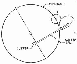
Fig. 404-Swinging-arm feed; Gear A driven by motor or turntable; gear
B, on cutter arm, meshes with A, causing the arm to swing.
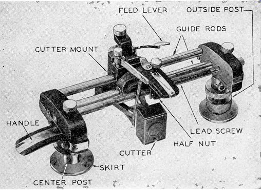
Fig. 405-An overhead lathe mechanism.
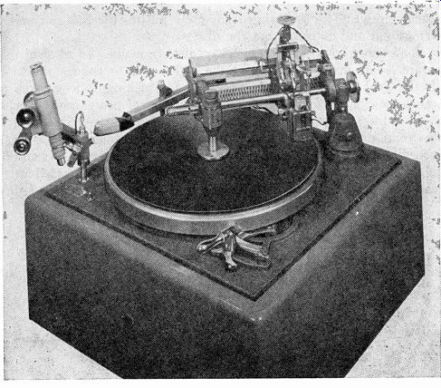
Fig. 406--A fairly elaborate overhead lathe recording table.
There are variations of the swinging-arm feed. One of these is shown in Fig. 404. Gear A is driven by the motor or turntable (through a reduction gear train to attain slow speed). The teeth of gear B, which is rigidly fastened to the cutter arm, engage with those of gear A, causing the arm to swing. Swinging arms are also made with friction drives, rather than lead screws or gears.
Lathe Mechanisms
Fig. 405 shows a mechanism of the lathe type. The outside post (the vertical support at right) is fastened permanently to the motor board. The mechanism may be raised by using the handle at the left, since there are horizontal and vertical pivots on top of the outside post.
To record, the center post at left, is placed over the center pin of the turntable. A small locking pin extends upward through most recording turntables. Both disc and center-post skirt are so oriented that the pin goes through 1 of the 3 holes in each. This locks turntable, center post, and disc together, so that one cannot rotate without the others.
T = TRACKING ERROR
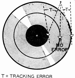
Fig. 407-Why tracking error occurs with the swinging-arm feed mechanism.
When the turntable and disc revolve, the center post also revolves.
The top of the center post and the left end of the lead screw are connected by a worm gear, so that the lead screw also revolves, though at a much slower speed. The cutter is rigidly fastened to the cutter mount, which slides freely along the smooth guide rods. When cutting is to begin, the feed lever is operated, engaging a half-nut in the mount with the lead screw. The revolving lead screw pushes the half-nut and the cutter mount and cutter across the disc.
Some more complex lathe mechanisms are made. In most of them, separate levers are used to lower the stylus and to engage the mount with the lead screw. This is desirable for making lock-grooves and spirals (see Section 12). Fig. 406 shows a typical professional mechanism, including a liquid (dash-pot) vertical damper to reduce vertical stylus motion due to vibration. It has such convenient accessories as a recording time scale, a crank for turning the lead screw by hand and a calibrated microscope. Various lead screws may be inserted in this mechanism to vary pitch (explained later in this Section) and direction of cut. There is, in all these mechanisms, some arrangement often a simple spring-to regulate stylus pressure.
Purchasing a Mechanism
Swinging-arm mechanisms are almost always cheaper than lathes, largely because they are simpler in construction. Because their operation is also simpler, they are more suitable for the layman. However, as can be seen from Fig. 403, before the motion of the lead screw reaches the stylus, it has to pass through 2 fairly long levers, rod A and the arm. These levers have a small amount of flexibility and the grooves, therefore, will not always be as evenly spaced as the lead screw alone would permit.
Another disadvantage is the tracking error introduced. Fig. 407 shows a cross-sectional view of the stylus tip. At one point, the flat cut ting face of the stylus is perpendicular to the groove, which is correct.

Fig. 408--A high-quality swinging-arm mechanism.
But as the arm moves in, the stylus cutting face is at an odd angle with respect to the groove. This distorts the groove shape and, to a certain extent, impairs record quality. Tracking error is invariably present to some degree in pickups, but since playback needles are round, not flat on one side, the needle contour presented to the oncoming groove is almost always the same, regardless of small tracking errors ; the error in a pickup, therefore, is not of such great importance. Tracking error in a cutter will not produce ideal records, although, for nonprofessional use, it is not too serious a defect.
Swinging-arm units are satisfactory for amateur use if they are solidly constructed. They are definitely indicated where expenses must be kept down, since excellent swinging arms are available at prices under 50, although more expensive ones, such as that in Fig. 408 are also made.
The lathe mechanism will usually space the grooves with accuracy, depending entirely on the precision of the lead screw threads. Since the parts are usually heavier, lathes are generally more solidly constructed than swinging arms, and will give more consistent results.
They are available at prices beginning under $100 and extending upward to several hundred. In deciding how much to spend on a lathe mechanism, the use to which it will be put is important. For making records and transcriptions for broadcasting or for reproduction by pressing (see Section 13), nothing but the finest is permissible. This means highly accurate lead screws and precisely machined parts allowing no excess play. If records are to be played on home phonographs, the requirements are less severe.
Units with time scales, vertical dampers, interchangeable lead screws, lead screw cranks, and other convenient accessories are desirable, but these conveniences are expensive and not by any means necessary. Even an inexpensive lathe, carefully adjusted and properly used, will give excellent results. No lathe, however, should be operated by a novice, and for that reason, if the recorder is to be used by a layman swinging-arm feed is a better choice than a lathe.
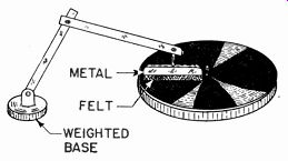
Fig. 409--One type of brush to sweep away the "chip".
Pitch and Direction
Lead screws come in a variety of pitches. The pitch at which the screw is threaded determines the number of lines per inch (l.p.i.) cut in the disc. To determine pitch of a record, place a ruler on the diameter and count the number of grooves appearing within 1 inch. Usual pitches are between 96 and 130 l.p.i. Of course, the higher the pitch the more recording time available on a given size disc. However, higher pitches mean smaller separation between grooves. A more accurate lead screw is necessary and audio volume must be more care fully controlled, so that there will not be enough excess stylus movement to cause cutting into the adjacent groove. A good compromise is 110 or 112 l.p.i. For recording times at various pitches, see Section 2.
Recordings may be made either inside-out or outside-in. Standard phonograph records are always cut outside-in, and most instantaneous records and transcriptions are made the same way.
During cutting, the stylus cuts a thread of material (known as the chip) out of the record coating. The chip is thrown inward by the stylus. When recording outside-in, some provision must be made for clearing away the chip before the stylus gets entangled in it. Several brushes are sold which may be laid on the record surface. They will automatically clear away the chip as it appears and wind it up around the center post. One of these is shown in Fig. 409. Many commercial recordists use a small tube, attached to the cutter, leading to a suction motor. Suction is the most convenient and safest way to remove chip, but the motor must be filtered for r.f. and a.f. interference.