THESE amplifiers have sufficient flexibility to permit variation of frequency response to suit the individual ear and to compensate for the falling off of high- and low-frequency response which is inherent in some components of the complete sound system.
Deluxe triode amplifier A number of intangibles go into the construction of an amplifier.
Proper balance of highs and lows, correct time intervals for transients and elimination of undesirable transients, adequate power for peaks and good low-frequency response without distortion, and correct coupling to the loudspeaker are a few important points which frequently are neglected. This neglect leads to the difficult to describe but very real sensation known as listener fatigue--a phenomenon not limited to low-priced equipment.
The advantages of having the preamplifier and controls in a separate chassis are many. However, this leads to greater complexity and cost. In this Section you have two forms of the basic amplifier, a deluxe model on two chassis and a utility model on one chassis.
Although both give excellent results, the two-chassis model has a number of additional refinements.
Fig. 1301 and Fig. 1302 are top and bottom views of the two-chassis model, and Fig. 1303 and Fig. 1304 give the schematics of the preamplifier and amplifier. The preamplifier, of course, can be used with any amplifier. Make sure that the power supply can take on the added load represented by the preamplifier.
In addition to having the necessary gain for a magnetic phonograph cartridge, the preamplifier has bass, treble, and loudness controls.
Also, a four-position switch, S1, is provided to compensate for the different types of high-frequency pre-emphasis used by the different record manufacturers. Position 1 gives nearly flat response, and will over emphasize the highs on most records with the possible exception of some 78 r.p.m. foreign discs. Position 2 is best for most 78-r.p.m. records unless scratch requires the use of positions 3 or 4, and also is best for Victor and Capitol LP's. Position 3 provides compensation for Columbia and other LP's. Position 4 is useful for playing worn and noisy recordings. The values of 15,000, 5,000, 3,300 ohms and .04 uF are correct for the G-E cartridge. If the Pickering cartridge is used these values should be changed to 10,000, 4,700, 2,700 ohms, and .03 uf, respectively. Those who wish still greater flexibility of record compensation can omit S1 and its associated components and substitute a Pickering 132E record compensator in the input circuit.
Switch S2 provides choice of pick-up from a magnetic cartridge or radio. The radio terminal also can be used for input from a crystal cartridge.
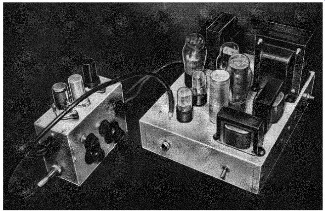
Fig. 1301. View of the two-chassis model of the all-triode amplifier.
All the controls on this model are conveniently located on the preamplifier
chassis.
The loudness control (or compensated volume control) can be assembled as shown on a 23-position switch. The loudness control is a refinement well worth having. A simple type (such as the IRC, LC1 or the Centralab Compentrol) may also be used. Of course, a 1-megohm volume control can be substituted at some sacrifice of bass perception at low volumes.
The bass and treble controls provide variations as shown in Fig. 1305. These curves have meaning only when considered in connection with the frequency range of the particular type of phonograph pickup used or the radio program listened to, the amplifier, and the speaker.
For instance, C1, .0001uf, in the bass control circuit increases the ratio of high to middle frequencies. If other components give relatively poor high-frequency response, it may be desirable to increase C1 to as much as .001 uf. The position of the bass control ahead of the treble control is no accident. This gives a more realistic bass than if these positions were reversed.
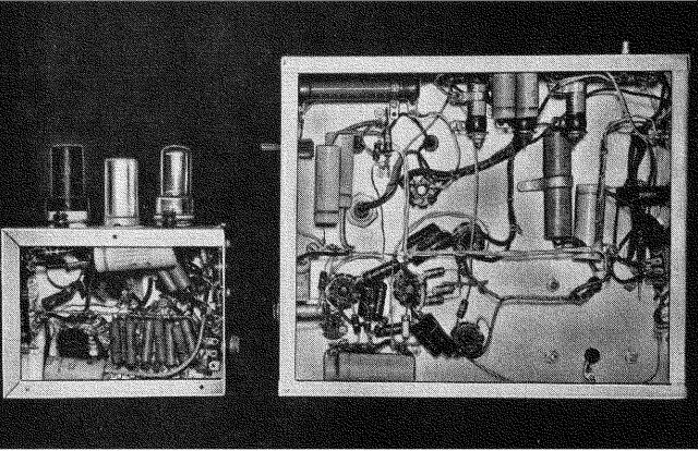
Fig. 1302. Bottom view of the amplifier. A spacious chassis permits
a tidy wiring job in the main amplifier.
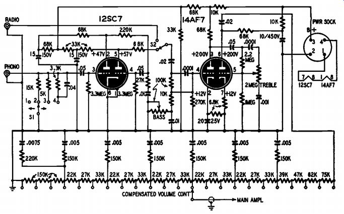
Fig. 1303. Preamplifier circuit. 23-position loudness control permits
full-frequency range reproduction regardless of amplifier output level.
The 12SC7 and 14AF7 tubes have their filaments connected in series and powered by d.c. from the power supply of the main amplifier. The preamplifier tubes were chosen because of their 150-ma filament current. Except for filament current and voltage, the 12SC7 is identical to the 6SC7, and the 14AF7 is very similar to the 6SN7. Watch polarity when connecting the 10041fd filament filter capacitor. The plus side of this capacitor goes to the chassis.
Several pairs of resistors and capacitors must be matched for proper balance in the main amplifier. The plate resistor R1 and the cathode load resistor R2 of the phase inverter must be the same. Plate resistors R3 and R4, grid resistors R5 and R6, grid capacitors C2 and C3, and grid capacitors C4 and C5 should all be matched pairs.
Grid bias of the 6B4-G tubes is a combination of fixed and self bias. The voltage drop across R7 plus the drop across the filaments of the preamplifier tubes gives a fixed bias due to the steady state current through all of the tubes and the bleeder resistor R8. On strong signal peaks when the output tubes draw more plate current, the voltage drop across R7 increases. This increases the bias on the 6B4-G's and pre vents overdrive of their grids. Approximately 10 watts undistorted output is available. The additional voltage drop across R9 and R10, although a minor contribution to the 6B4-G's bias, primarily is a balancing device to balance the plate currents of the 6B4-G tubes.
This amplifier has ample volume. However, if more is needed, add the 20-g, 25-volt cathode-to-ground-capacitor shown in dotted lines on the first section of the first 6SN7.
The power transformer must provide at least 150 ma at 400 to 450 volts to center-tap. Use one with a 200-ma rating. It also must have a 5-volt winding for the rectifier tube and two 6.3-volt windings. These two 6.3-volt sources are required for proper bias and balancing adjustment of the 6B4-G's. One of them can be supplied from a separate fi lament transformer.
The total plate current supplied to all tubes is about 95 ma. Bleeder resistor R8 provides additional drain to give a d.c. of 150 ma through the rectifier tube. This 150 ma passes through the filaments of the preamplifier tubes.
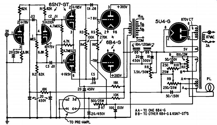
Fig. 1304. Circuit of the amplifier. Full audio output of the unit is
10 watts.
One-chassis model
Fig. 1306 and Fig. 1307 show the one-chassis utility model built on the TG-10 keyer chassis and Fig. 1308 gives the schematic. This model requires fewer and less expensive components and only one adjustment, that of R7 to 780 ohms. The 6B4's should be matched for mutual conductance at the time of purchase, if possible. The power transformer should have minimum ratings of 120 ma at 350 volts to center tap. A separate filament transformer can be provided to replace one of the 6.3-volt windings. Do not skimp on the output transformer.
Of course, as many of the refinements of the two-chassis model as desired can be incorporated in the one-chassis model.
Construction hints
There is nothing critical about constructing this amplifier. To make sure there is plenty of room in the two-chassis model, a 3 x 5 x 7-inch chassis is advisable for the preamplifier and a 3 x 10 x 12-inch chassis for the amplifier. Do not cable together wires which carry signal currents and do not place components which carry signal voltages on a common terminal strip.
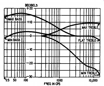
Fig. 1305. The frequency response curves showing the effect of the tone
controls.
Locate the tube sockets so that coupling capacitors can be placed with short leads from tube terminal to tube terminal. Supply B-plus voltage from a common bus or terminal strip located along one side of the socket layout through the load resistors directly to the socket terminals. Along the other side of the socket layout place a common ground bus to which appropriate connections can be made. Connect this ground bus to the chassis at only one point and locate this point as close to the signal input terminal as possible. In the two-chassis model the one-point grounding procedure should be followed in both preamplifier and amplifier to avoid chassis current effects.
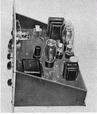
Fig. 1306. Photo of the one-chassis unit.
Resistor R8 in Fig. 1304 gets rather hot. Attach it to the side of the chassis at both ends and bore ventilating holes along the side of the chassis both above and below this resistor.
From the preamplifier to the main amplifier chassis filament ground and signal ground are carried separately and connected together at the main amplifier ground bus.
The 12SC7 and 14AF7 tubes in the preamplifier should be shock mounted. In the utility model the 6SC7 preamplifier tube should be shock mounted.
In the utility model, a chassis bottom plate helps to cut down direct hum pickup by the compensating network which comprises the input to the 6SC7. It is best to operate the 6SC7 and the 615 from a separate filament winding or transformer to reduce hum.
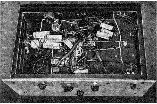
Fig. 1307. Underside of the one-chassis unit. Careful parts placement
simplifies wiring, makes neater looking job, simplifies future possible
trouble-shooting.
Adjustments
Adjustments must be made in the two-chassis model so that the current to each 6B4-G tube is 40 ma and the current to the preamplifier filaments is between 140 and 150 ma.
Proper adjustment of the 7.5 K, 50-watt pot, R8, can be made by inserting a d.c. milliammeter in series with the preamplifier filaments.
Adjust R8 for a reading of 150 milliamperes. You will find some interaction between the settings of R7 and R8. Adjust R7 for proper 6B4-G bias and R8 for correct preamplifier filament current. An alter native method is to adjust R7 to 400 ohms and R8 to about 7,000 ohms.
Measure the current in the plate circuit of each 6B4-G individually, and by adjusting R9 and R10 balance these two currents at any convenient value between 40 and 50 ma. Then adjust R8 until the voltage between terminals 1 and 4 on the power socket to the preamplifier measures 22 to 24 volts. Next recheck the 6B4 plate current and by means of R9 and R10 adjust to 40 ma each. Again check the filament voltage to the preamplifier and adjust R8 to make this voltage 23 to 24 volts. Repeat the resistor adjustments if necessary until the proper currents and voltage are obtained. Normally R7 is left at 400 ohms.
--------------
Materials for Preamplifier
Resistors: 1-3,300, 1-5,000, 2-6,800, 3-10,-000, 1-15,000, 5-22,000, 6-27,000, 8-33,000, 1-39,000, 1-47,000, 1-62,000, 6-68,000, 1 75,000, 1-100,000, 9-150,000, 2-220,000, 1 270,000-ohm, 1-1, 1-2.2, 2-3.3-megohm, 1 / 2* watt; 1-100,000-ohm, 1-2-megohm potentiometers.
Capacitors: 2-.0001-0 mica; 1-.001, 6-.005, 1-.0075, 2-.01, 2-.02, 1-.04, 3-.05-0, 400 volt, paper; 1-10-pf, 450-volt, 1-15-gf, 150 volt, 1-20 uf, 25-volt electrolytic.
Miscellaneous: 1-12SC7, 1-14AF7 tubes and sockets; 1-23-position rotary, 1-4 position, single pole, switches; 2 -phono jacks; 1-4 prong power socket; chassis, hookup wire, as sorted hardware.
Materials for Amplifier:
Resistors: 1-4,700, 2-6,800, 1-10,000, 2-18,-000, 3-82,000, 2-100,000, 2-270,000-ohms, 1-1, 2-4.7-megohm, 1 / 2 -watt; 2-250-ohm, 25 watt, 1-500-ohm, 25-watt, 1-7,500-ohm, 50. Watt, with adjustable tap; 1-100,000-ohm potentiometer.
Capacitors: 2-.01, 1-.03, 2-.08-0, 400-volt, paper; 1-161.4f, 500-volt, 5-20-0, 450-volt, 1-25-0, 25-volt, 2-50-0, 150-volt, 1-100- 4 150-volt, electrolytic.
Miscellaneous: 2-6SN7-GT, 2-684-G, 1-5U4 G tubes and sockets; 1-435-0-435-volt, 200 ma power transformer with two 6.3-volt windings and one 5-volt winding; 2-10-h, 120-ma chokes .1-audio output transformer (Acrosound model TO-250 or equivalent, 12.5 watts, 5,000 ohms primary impedance); 1-4-prong power plug; 1-3 amp fuse and fuse holder; 1 -phono input jack; 1-s.p.s.t. line switch; chassis, hookup wire, assorted hardware.
Materials for One-Chassis Amplifier:
Resistors: 1-3,300, 1-4,700, 1-5,000, 2-6,800, 4-10,000, 1-15,000, 1-27,000, 3-33,000, 2 68,000, 3-82,000, 4-100,000, 1-220,000, 4 270,000-ohm, 1-1-megohm, 1-2.2, 2-3.3, 2 4.7-megohn, 1 / 2 -watt; 1-1, 1-2-megohm potentiometers; 1-1,000-ohm, 25-watt with adjustable tap.
Capacitors: 2-.0001-0, mica; 1-.001, 5-.01, 1-.02, 1-.03, 1-.04, 2-.05, 2-.08-eif, 400 volt paper; 1-8, 2-15, 1-50- 4 150-volt, 5 20-0, 450-volt, electrolytic.
Miscellaneous: 1-6J5, 2-6SN7-GT, 2-684-G, 1-6SC7, 1-5U4-G, tubes and sockets; 1- power transformer, 435-0-435-volt, 200-ma, with two 6.3-volt and one 5-volt winding; 1- output transformer (Acrosound TO-250 or equivalent 12.5 watts, 5,000 ohms primary impedance); 1-10-h, 120-ma choke; 1-s.p.s.t. power switch; 1-s.p.d.t. switch, 1-s.p. 4-position, switch; 1-3-amp fuse and fuse holder; 2 -phono jacks; chassis, hookup wire, assorted - hardware.
-------------------
Its value can be changed somewhat if necessary for proper adjustment.
As these adjustments must be made with the amplifier on, the secondary of the output transformer must be connected either to a speaker or better to a 10-watt, 4- to 16-ohm resistor during the adjustment to make sure that the transformer does not burn out.
Set the hum-balancing potentiometer R11 for least hum. On the radio input the hum level is more than 75 db below maximum signal.
In the utility model R7 has a different value than in the two-chassis model. Set it at 780 ohms or better, then adjust it to give an average 6B4-G plate current of 40 ma.
In both amplifier circuits, it is important to have equal signal driving voltages on the control grids of the output tubes. Check this by feeding in a steady tone from an audio generator and measuring the signal voltage across the 6B4-G grid return resistors, R5 and R6.
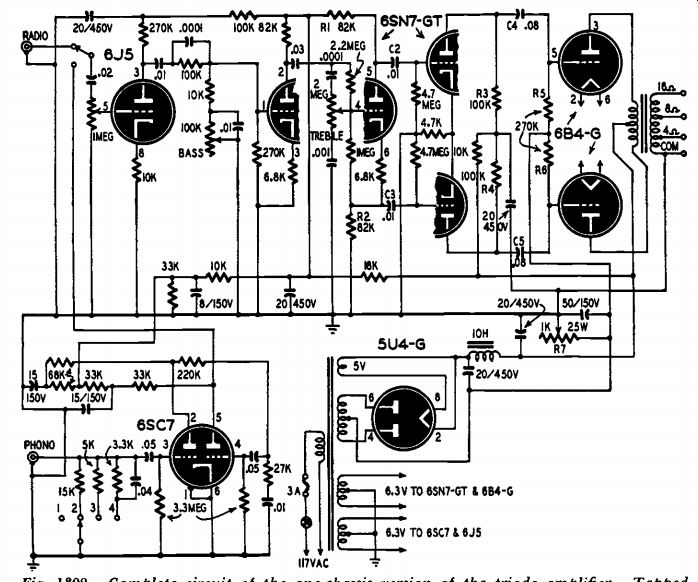
Fig. 1308. Complete circuit of the one-chassis version of the triode
amplifier. Tapped output transformer allows choice of different speaker
impedances.
Listening tests
Various versions of this amplifier have been given long-range listening tests using several crystal, General Electric, and Pickering phono-graph cartridges, disc recordings from many sources, and AM and FM radio programs. Speakers have included an 8-inch electrodynamic in a conventional console cabinet, a 15-inch Jensen coaxial in both the same cabinet and in a bass reflex enclosure, a single 12-inch electro dynamic in a bass reflex enclosure, and a Klipsch speaker system.