THE audio amplifier described in this Section is a miniature, high fidelity, 4-watt, a.c.-d.c. amplifier that is flat ± 1-1/2 db from 30 cycles to 10 kc, has less than 2% distortion, a gain of 60 db, and a noise level 70 db below 4-watt level. Tubes used are two 50B5's and a 12AU7.
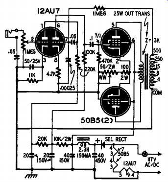
The amplifier is constructed on a 4 x 5 x 2-inch aluminum chassis, and over-all measurements are 5-1/2 x 6 x 4 inches. It takes less than half the space of a conventional amplifier using 501.6's. The push-pull 50B5's are employed in a cathode-driven phase-inversion circuit (see schematic, Fig. 1401), and the two triodes of the 12AU7 are in cascade.

Fig. 1401. Amplifier schematic. Output power is approximately four watts.
This results in 10 times the gain that would be possible if the two triodes were used in the conventional type of inverter circuit.

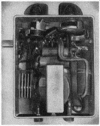
Fig. 1402. Getting components into small space can be done with planning.
Although the two triodes in the 12AU7 envelope are identical, the circuit constants are different, being designed for minimum distortion at the levels presented to each.
It is almost impossible to show the actual placement of chassis connections in the circuit schematic, but care in these is most important for low noise level. See Fig. 1402 and Fig. 1403 for layout of components. There are but three chassis connections and they all go to the lugs on the 12AU7 socket. Buses run from here to the metal-can capacitors, the only other chassis connections. (An additional minor one is the 50-ohm bias control for the 50B5's.) The input jack is insulated with fiber washers. One ground point instead of several results in less inductive hum pickup because of elimination of closed low impedance loops. This feature of the amplifier is a major contribution to its low noise level. The wiring is as compact as possible, and signal leads are close to the chassis and well shielded. Filament leads are twisted tight, the chassis-connected end of the string going to pin 4 of the 12AU7 voltage amplifier.
Many other points of mechanical construction in the amplifier help stability and keep noise down. For example, the lugs of the phono jack are moved close together. A shielded lead covered with spaghetti runs from this jack to the 12AU7 socket, and the inside lead is drawn out through an appropriate hole to make connections at the volume control. Center socket shields are grounded. Whenever possible, socket lugs are soldered together without utilizing wires. The a.c. plug and switch are kept close together and on the opposite side of the chassis from the input jack. Output jacks are mounted on the other end of the small chassis.
It is necessary to mount the filter choke directly underneath the output transformer, but no trouble has been experienced with hum.
The cathode bypass capacitor in the first stage does not raise gain, as it would appear, but eliminates hum. Incidentally, a 450-volt capacitor is used instead of a 150-volt unit on the input of the B-plus filter to minimize maintenance, as it is subject to surges. For the same reason a selenium rectifier instead of a vacuum tube is used. The filter capacitors are exposed to a considerable amount of heat, but the Mallory FP units used are designed for this and have proven that they can take it without going bad.
The cathode phase-inversion circuit of the 50B5's permits economical use of tubes. It is also probably the best for maintaining balance through wide frequency bands. It is not unstable, tricky, or difficult to adjust. The reason for the wideband performance is that no capacitors are involved. The phase-inverting cathode resistor is made equal to the reciprocal of the tubes' transconductance and is adjustable. (The transconductance of 6B5's is in the order of .0075 mho; thus the resistor is adjustable around 133 ohms.) A cathode-coupled phase-inverter has the gain of a single tube, the signal voltage being effectively split and half applied to each side of the push-pull circuit.
This is how it works. The signal from the 12AU7 is coupled to the grid of the upper 50B5 in the usual way. The cathode of the 50B5 is unbypassed. The signal plate current, passing through the cathode resistor to ground, creates a voltage drop between cathode and ground, which changes at an audio rate. The grid of the lower 50B5 is grounded and its cathode is connected to that of the upper tube.
Any voltage appearing across the cathode resistor as the result of signal through the upper tube, also appears between cathode and grid of the lower tube.
------------
Materials for Miniature-Tube Amplifier
Resistors: 1-100 ohm, 2 watt, 1-4,700 ohm, 1-10,000 ohm, 2 watt, 1-20,000 ohm, 1 100,000 ohm, 1-220,000 ohm, 1-1 megohm; 1-50-ohm, 2-watt potentiometer, 1-1 megohm potentiometer.
Capacitors: 1-.00025 µf, 3-.05 uf, 1-.1 1-50 uf, 25 volt, 2-20 µf, 150 volt, 1-40 µf, 150 volt, 1-40 µf, 450 volt.
Miscellaneous: 1-selenium rectifier, 150 ma, 1 filter choke, 150 ma, 1 jack, 1 output trans former, 3-miniature tube sockets, 1-12AU7, 2-50B5, 1-chassis, 2-knobs, assorted hard ware.
-------------

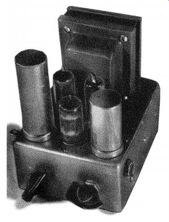
Fig. 1403. Complete miniature amplifier.
Chassis measures only 4 x 5 x 2 inches.
There are several ways of adjusting the bias of the tubes for balanced inversion. Probably the best and easiest is to note with a pair of headphones (connected to the 500-ohm output) the point at which the hum is balanced out. The adjustment is brought all the way up until a loud hum is heard in the phones and then gradually worked down to the position where the hum just fades out.
An ideal feedback loop should go from output to input. In this amplifier the volume control is in the first stage, and feedback introduced here would change with the setting of the volume control. To overcome this difficulty the feedback is applied to the second stage.
As the first stage works at a very low level, it contributes negligible distortion. The output transformer and power tubes are the greatest contributors to distortion.
The use of inverse feedback to flatten response calls for a feedback loop with no frequency discrimination. Since no capacitors are used, the feedback loop in our amplifier meets this requirement. The grid resistor of the second 12AU7 triode returns to ground through the secondary of the output transformer.
When the output winding of the transformer is in the feedback loop, there is a frequency at which the phase of feedback is reversed due to the stray inductance of the windings. At this frequency there is oscillation, a.f., ultrasonic, or r.f. While the oscillation may be inaudible, it may overload the amplifier and distort the audible signal.
The 1-megohm grid resistor and the 250-µktf capacitor isolate the inductance of the transformer and provide a low-impedance path to ground for r.f. and ultrasonics.
The polarity of the primary and secondary of the output transformer must be correct so that the feedback is negative, not positive.
If it is not right on the first try, interchange the connections.
Frequency runs at various levels have been plotted, and there is much improvement in performance when the output transformer is run well under saturation. This is the reason for a 25-watt trans former in a 4-watt amplifier; the larger the transformer, the better the bass response and the lower the distortion.
(Note this warning carefully: the chassis and the capacitor cans in this amplifier are directly connected to one side of the line -and it may be the hot side!) To make the amplifier safe for use, several methods are possible, though none are entirely safe and precaution is still required.
The entire unit may be enclosed in a nonmetallic cabinet so that no metal part can be touched. If the input is "isolated" from the line with a .05-µf capacitor, a phonograph pickup connected to it may be touched with little danger.
The best procedure is probably to bring all points shown connected to chassis to a common negative point, from which the chassis can be entirely isolated. Two-terminal filter capacitors with insulated cans would, of course, be necessary. This method is used in under writer-approved receivers, most of which also use an .05-uF capacitor between chassis and negative B. Another method would be to orient the power plug in the wall socket so that the chassis side of the line is the grounded side. The socket and plug can then be so marked that the orientation will be the same in the future. While electrically preferable, this method is psychologically unsound--even a brilliant radioman will forget some day and get burned. If, however, the amplifier is to be connected to a tuner or any other powered device, the polarized-plug trick is the only way to be safe--and it may also be the only way to keep out hum.