THE crossover network design data in Section 3 specifies the inductance of the coils in millihenries. Too often, it is hard to find information about how many turns of wire to wind on a form of given dimensions to obtain a required value of inductance.
Fortunately, there are approximate formulas which can be used in designing network inductors. The results obtained will be close enough for practical purposes if care is used in their application.
Many variables are involved in winding inductors of any sort. For instance, the number of turns that any multilayer form will hold depends not only upon the diameter and insulation of the wire used, but also upon the method by which the wire is applied to the winding space provided. Obviously, if the wire is crooked or wound loosely about the form, valuable winding space will be lost. Each turn must lie on top of the preceding turn if the maximum number of turns is to be wound in the space provided.
One good method of winding wire on the coil form is to clamp a hand drill in a vise, then place a bolt or machine screw through the core of the form and fasten it securely with a lockwasher and a nut.
For large or rectangular cores, use a wooden form cut to fit the core and drilled for the bolt. The length of the bolt should be such that when the bolt is clamped in the drill chuck, the form will be as close to the chuck as possible. Such an arrangement leaves one hand free to keep the wire taut while the other is occupied turning the drill crank.
Four circuits are shown in Fig. 401. Those in 401-a and 401-b use the conventional m-derived network; those in 401-c and 401-d have the constant-resistance type of network. Fig. 401-d is the same as Fig. 302-d in Section 3. The necessary formulas for calculating values of inductance and capacitance in either case are given.
Since the purpose of this Section is to supply adequate information for winding the inductors to be used in the networks of Fig. 302 and Fig. 401, we will leave it up to the reader to determine the value of capacitance or inductance required by simply using the formulas shown.
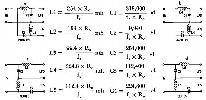
Fig. 401. Four types of dividing networks and formulas for computing
their values.
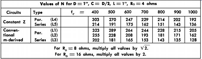
TABLE I
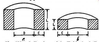
Fig. 402. Coil a is used in Table I. Coil b represents square cross-section
coils of Table II.
A typical example
Suppose the type of network chosen is the constant-resistance series circuit of Fig. 401-d. Let us also suppose that the forms on which the inductances are to be made have a measured diameter of 1 3 / 8 inches, and a winding length L of 1 inch is available. The winding depth, C, is equal to half the diameter, D, as shown in Fig. 402-a.
The value of N (number of turns) for a diameter, D, of 1 inch is given in Table I. All values of N in Table I are based on a diameter, D, of 1 inch, a winding depth, C, equal to half the diameter of the form, a winding length (L) of 1 inch, and a voice-coil, Ro, impedance of 4 ohms. Note that in Table I, if Ro is 8 ohms, you should multiply all values by 1.414 (square root of 2). Similarly, if Ro is 16 ohms, multiply all values by 2. If, for example, the desired crossover frequency is to be 800 cycles, the value of N (in Table I) is equal to 151 turns.
In other words, coils marked L5 in Fig. 401-d should have 151 turns.
This value, however, is for a D of 1 inch, and for other diameters a correction factor must be applied to this value of N. These factors are given in Table III. The factor for 1 3/8-inch-diameter form is 0.79.
Hence, all values of N (Table I) should be multiplied by 0.79 if a 1% inch form is used to wind the coils.
In the example: 151 x 0.79 = 119 turns.
If the voice-coil impedance of the woofer is 8 ohms instead of 4 ohms, the value of N (119) must be multiplied by e or 119 X V- 2 «. 169 turns.
This value of N is the number of turns needed on the form for a crossover frequency of 800 cycles and an impedance, Ro, of 8 ohms for the loudspeaker voice coil.
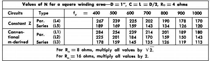
TABLE II
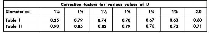
TABLE III -- Correction factors for various values of D
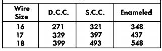
TABLE IV -- Turns per square inch for various sizes and types of wire
The next step is to determine the size and type of wire to use in winding the inductances. Since, in this example, we are using a coil form having a diameter of 1 3 / 8 inches (1.375 inches), the available winding space is equal to the winding length, L, times one-half the diameter of the form: L X 0.5 X 1.375 = 0.688 sq. in.
A size of wire which will wind 169 turns in 0.688 sq. in. or 246 turns per square inch must be used (169/.688 -= 246 turns / in.^2). The number of turns per square inch for various sizes and types of wire is given in Table IV. From this table, No. 16 d.c.c. will wind 271 turns per square inch. However, in the winding space of 0.688 square inch, 271 X 0.688 = 187 turns of No. 16 d.c.c. can be wound. This is 18 turns more than the required number and will cause the crossover frequency to be about 140 cycles lower than 800 cycles. Adding one half of the difference between 169 turns and 187 turns to the required number of turns (169) will raise the crossover frequency to approximately 800 cycles. The foregoing statement will not be true in all cases, but can be used as a means of minimizing the changes in the coils at the final testing of the network.
If the winding area is to be kept square in cross section, the values of N for various crossover frequencies are as listed in Table II. Correction factors for various diameters to be used with Table II can be found in Table III, and in all cases these factors should be multiplied by the values of N listed in Table I and Table II. The values of N in Tables I and II were obtained by using Wheeler's and Bunet's formulas for multilayer inductances as given on pages 148 and 149 (third edition) or pages 443 and 444 (fourth edition) of the Radio Iron Designer's Handbook.