WHEN only one loudspeaker is used with an amplifier, correct connection is relatively simple. The speaker is connected to the amplifier output tap whose impedance, as marked, most nearly approaches the speaker impedance. Even this simple operation, however, may be beset with problems if the speaker is located far from the amplifier.
When a number of loudspeakers are operated from an amplifier, as in a large sound system, and the power fed to each speaker is different, the fun starts! This Section is intended to present a few simple rules to help the sound technician do a properly engineered job with pre assured results.
The term "transmission line" brings to mind high mathematics, nepers, and surge impedance, especially if associated with television. In audio, things are simpler. An audio transmission line is just a pair of wires that connect one audio device to another, as, for example, an amplifier to its loudspeakers. Surge impedance, propagation constant, etc., don't bother us until the line gets pretty long, say a good fraction of a wavelength. At audio frequencies (15,000 cycles) a 1/4-wave length line is some 3 miles long, and the length increases as the frequency gets lower.
Two things plague the audio man: conductor resistance and shunt capacitance. The former causes power losses (heat) and the latter limits high-frequency performance. Their effects depend on the line impedance.
The impedance of a line is the nominal value (magnitude) of the impedance across the receiving end of that line. The definition is so stated because in high-quality audio amplifiers, the source impedance, looking back into the amplifier, may be but a fraction of the load impedance. Thus the same pair of wires can be a 4-ohm line, a 16-ohm line, or a 500-ohm line, depending on the load.
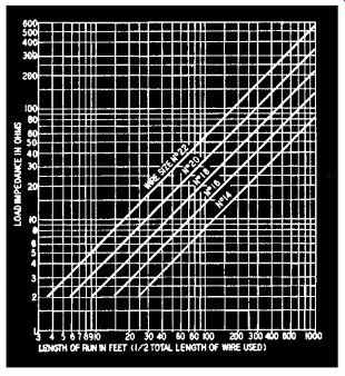
Fig. 501. Chart of maximum line length for given wire size and impedance.
Selecting a speaker line
All conductors have resistance. Accordingly, when current flows in the line, there is a loss of power, the energy being converted into heat.
Resistance losses -or copper losses as they are sometimes called -may be minimized by using larger diameter conductors and by making the line as short as possible. Copper losses are most important on low impedance (16 ohms or less) lines since the lower the impedance, the more current flows for a given power, and there is greater PR power loss as heat.
Commercial sound engineers usually like to use the smallest possible wire size because the smaller sizes are less expensive and are easier to install and conceal in existing buildings. The smaller the wire size, the greater the resistance per foot and the greater the power loss, so a compromise must be made. Sound engineers allow 0.25-db loss (about 5% power loss) in the wiring to speakers.
To eliminate calculations, Fig. 501 has been prepared to show the maximum length of line which can be used for various line impedances and wire sizes. The chart is simple to use. For example, a single 16 ohm loudspeaker can be connected to an amplifier with No. 18 wire and can be any distance up to 75 feet from the amplifier. For No. 14 gauge, the distance may be up to 190 feet.
Three conditions may occur when using the chart:
1. If the point of intersection of the line length and load impedance falls above the line labeled No. 22, No. 22 wire or any larger size may be used. Smaller wires are not recommended.
2. If the point falls between two curves for wire size, the larger size should be used.
3. If the point falls below the curve for No. 14 wire, the load impedance is unreasonably low for the length of line required and matching transformers to make the line impedance higher must be used.
This point will be considered a little later.
Multiple speaker installations
Installing a single loudspeaker involves no problems since its impedance may be used directly in finding the wire size from the chart.
When two or more loudspeakers are used, there are two methods of connection: series and parallel. The series connection is often attractive but is not recommended except as an emergency measure. There are two reasons for this: the series connection is unreliable because if one speaker fails the entire series group is silenced. At some frequency a loudspeaker goes through cone resonance and its impedance becomes much greater than its nominal impedance value. Where several speakers are used, especially several makes or several sizes, their resonant frequencies may be different. When one speaker in a series string goes through resonance, there is a change in the sound volume from the other speakers. This effect can be very annoying, and is almost entirely absent in parallel-connected speakers.
When two or more speakers are connected in parallel, their impedances are combined in the same way as parallel resistances. The equivalent impedance of the total speaker system is used in the line chart, Fig. 501, in the same way as that of one speaker. The group is connected to the amplifier tap which corresponds to the equivalent impedance of the system. If an exact tap is not available, connect to the next lower amplifier output tap.
Assume that we have three speakers, each with a voice coil impedance of 16 ohms, and that the group is to be 30 feet from the amplifier.
The equivalent impedance of the speaker load is 16/3 or 5 1/3 ohms. On the chart, Fig. 501, the point of intersection of 5 ohms and 30 feet falls between the curves for No. 18 and No. 16 wire. Thus No. 16 wire is the smallest wire that can be used.
The speaker line should be connected to a 5-ohm tap, but most amplifiers do not have a 5-ohm tap, so the line should be connected to the 4-ohm tap, a common value. The reason for using a lower tap is that an output transformer reflects to its primary an impedance which is the load for the output stage. Connecting a slightly higher load to a tap, as in this case, causes the reflected impedance to be higher in the same proportion, which is better for an amplifier than having a slightly lower load.
When several speakers have their voice coils in parallel, the impedance of each voice coil should be the same. Any parallel system is a constant-voltage system and the voltage across each speaker is the same.
Each speaker will draw the same power, and, assuming equal efficiency, will deliver the same sound level.
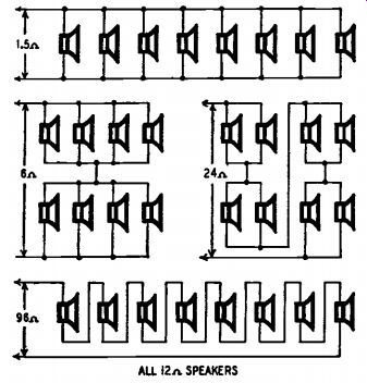
Fig. 502. Four ways of connecting eight 12-ohm speakers to receive equal
power.
If several values of impedance are used in parallel, as two speakers of 8 ohms and one of 4 ohms, each 8-ohm speaker draws only half the power of the 4-ohm speaker. This unequal power distribution may be useful at times to provide different power levels in speakers. However, unequal amounts of power distribution are best distributed with matching transformers and higher impedance lines. Parallel combinations often give nasty combinations of impedances; the line impedance gets below 4 ohms and that makes for short runs or big wire or both. The best method is to use equal impedance and power distribution for these voice coil lines, and keep the line impedance 4 ohms or higher.
Voice-coil impedances range from 2 to about 16 ohms. (Sometimes values outside this range are met, but they are not common). Let us take 12 ohms for some examples because it makes calculating easier.
Suppose eight such speakers are connected, all to receive the same power. The arrangements shown in Fig. 502 give over-all impedances of 1.5, 6, 24, and 96 ohms. It is probable that even a multi-ratio output transformer will not provide most of these matchings, so some other arrangement must be figured out, including one or more resistors, as "dummies" to pad out the values. And the number of speakers in an actual installation may not be so convenient for series-parallel connection as our example of eight.
Matching transformers
In discussing the speaker line chart, Fig. 501, it was pointed out that in some cases the length of line is great for the load impedance, and the line loss is greater than 0.25 db unless very heavy conductors are used.
For such cases we borrow a trick from the power engineers who deal with power transmissions over long distances. The power boys get around the problem of line loss by stepping up the voltage at the sending end and stepping it down at the receiving end.
Audio engineers use a similar stunt with an output transformer at the amplifier that has a different turns ratio (gives higher voltage) than those ordinarily used with voice coils. Sometimes both voice coil and line impedances are present on the output taps. The usual line impedance is 500 ohms although 250 and 125 ohms are used. Broadcast engineers usually use 600 ohms as a line impedance because telephone lines (used for low levels only) have about 600 ohms characteristic impedance.
Impedances greater than 500 ohms are not used because shunt capacitance in long lines causes rolloff in response at the higher audio frequencies. When using a 500-ohm line, a matching transformer is used at each speaker (or group of speakers) to step down the line voltage to values suitable for voice coils. The speaker matching transformer reflects the voice coil impedance to 500 ohms (or other value depending on the line impedance). This fundamental axiom is often overlooked, but should be stated for the sake of completeness. The rated power of the speaker or speakers should be at least equal to the rated power output of the amplifier; and the rated power of the amplifier should be equal to the total power desired in the speakers. The first proposition assures that the speakers will not be overloaded, and the second that they will provide adequate sound. Not all amplifiers will put out their rated power even at mid range frequencies, but following this simple rule and using good amplifiers will assure success.
In laying out a 500-ohm distribution system one rule covers all cases of equal or unequal power distribution:
1. Determine the power to be fed to each speaker or group of speakers.
2. Select an amplifier capable of this power, and multiply the amplifier power by the desired line impedance.
3. Divide the number obtained in step 2 by the power desired in the first speaker or group of speakers. This quotient is the primary impedance of the matching transformer for the speaker (s).
4. Repeat step 3 for each speaker or group of speakers.
Some typical cases
The use of the rule is best shown by examples of several types of matching situations.
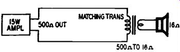
Fig. 503. One speaker on a 500-ohm line.
Fig. 503 shows a single speaker fed by a 15-watt amplifier through a 500-ohm line. The power capacity of the speaker is 30 watts and its nominal impedance is 16 ohms. Here the limiting factor is amplifier power and we proceed to step 2: 15 X 500 is 7500. Dividing by 15 (as all the power goes to one speaker) gives us 500 ohms as the correct primary impedance for the matching transformer. The secondary impedance is 16 ohms.
Had there been four speakers to be fed from one transformer, the primary impedance would have been the same, but the secondary would be set for four ohms. In this case the total power for the group is still 15 watts (used in step 3) but the power per speaker is 15/4 or 3.75 watts. The case is shown in Fig. 504.
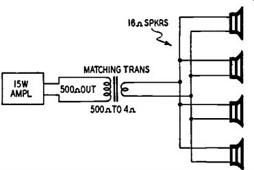
Fig. 504. Power per speaker is 3.75 watts.
Fig. 505 shows four speakers strung along a 500-ohm line. If there is considerable separation between speakers, it is best to use a separate matching transformer at each speaker. Let us say that we have a 20 watt amplifier and the desired power per speaker is 5 watts. The rated power of each speaker being 10 watts, we are safe. In step 2: 20 X 500 is 10,000. In step 3: we divide 10,000 by 5, giving us 2,000 ohms as the primary impedance for each transformer. Since each speaker has the same power, we need calculate but once. The secondary of each matching transformer is set to the impedance of each voice coil which need not be the same for all speakers.
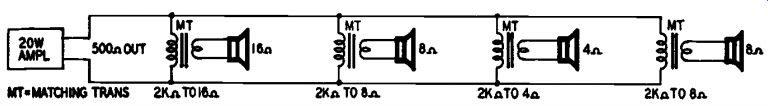
Fig. 505. Each speaker needs a matching transformer if the lines are
long.
Let us proceed to a problem shown in Fig. 506 where we have unequal power distribution. A 10-watt amplifier with 500-ohm output is to feed three speakers. The first is to be fed 1 watt, the second 4 watts and the third 5 watts. For this type of circuit each speaker must be equipped with a matching transformer even though they are near each other. In step 2 we multiply 500 x 10 to get 5,000. Dividing by 1 in step 3 gives us 5,000 ohms for the primary impedance of the matching transformer for the first speaker. The secondary is set for the correct voice-coil impedance. For the second speaker, (step 4), we divide 5,000 by 4 to get 1,250 ohms for the matching transformer primary. Repeating for the third speaker we get 1000 ohms as the impedance for the third matching transformer. To check the calculations, we can combine the three impedances as parallel resistors. We get 500 ohms, which shows that we have a matched system.
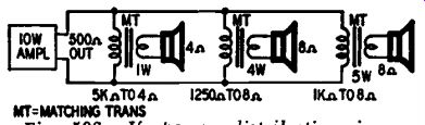
Fig. 506. If power distribution is unequal, each speaker needs transformer.
The 500-ohm line is not a sacred cow. Lower impedances such as 250 ohms will work equally well if larger wires are used for runs over 400 feet. This information is obtained from Fig. 501. A lower impedance sometimes may be required. For high power amplifiers with many speakers the required primary impedance of some of the matching transformers may be greater than 10,000 ohms. In this case the line impedance should be lowered to say 250 ohms, as high quality matching transformers are generally not made with primary impedances higher than 10,000 ohms.
If there are several speakers to be fed from a single matching transformer, the speakers need not be adjacent to each other. For example, one of the speakers of Fig. 504 could be up to 30 feet from the matching transformer, if it is connected with No. 16 gauge wire or larger. Fig. 501 should be consulted to find out if such a scheme (which reduces cost because wire is cheaper than good matching transformers) is practicable.
The maximum recommended length for speaker lines, even at 500 ohms, is 1,000 feet. One reason is that the shunt capacitance in a 1,000 foot line may build up to the point where it is a severe restriction on quality. In high-fidelity work loss of high frequencies is disastrous. In public address work loss of high frequencies causes a reduction in intelligibility and a decrease in the usefulness of the system.
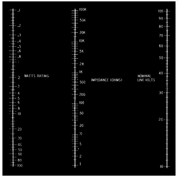
Fig. 507. Constant-voltage chart, showing impedance vs. wattage.
Another reason is power loss. If kept to 0.25 db, that is a 10% power loss. In a 50-watt system it means 5 watts lost. The cost per watt in amplifiers is high, so losses mean money. If a speaker line must be run much over 1,000 feet, it is better to put a booster power amplifier nearer the speakers and feed it on a 500-ohm line at lower power level where a 10% loss means fewer watts. Such a scheme permits equalization to counteract loss of high frequencies. Speaker lines can be run over 1,000 feet if the limitations are known and efforts are made to minimize their effects.
The constant-voltage system is usually designated by the nominal voltage used. The American standard is a 70-volt line; the European, a 100-volt line. The constant-voltage system has one apparent disadvantage -a separate output transformer is required for each speaker. The circuits in Fig. 505 and Fig. 506 are constant-voltage systems. The disadvantage in using multiple output transformers is more apparent than real. True, when an amplifier is working only one speaker, located close to it, there is no point in using more than one transformer for matching the output to the speaker. Doing the matching in two steps adds to cost by one transformer, and also adds slightly to the audio losses. But when the amplifier is feeding a number of speakers, matching problems may well make separate transformers worth while.
The constant-voltage line has another advantage: It is always best to operate dynamic type speakers in parallel, otherwise electrical damping is lost, and peculiar effects due to interaction between speaker impedances are noticed. In constant-voltage operation, all units are always parallel-connected, even when the power delivered to different units is varied. If numbers of speakers are operated in parallel by direct connection, the resulting impedance is so low that much of the output power is lost in connecting lines unless very large cable is used. In the constant-voltage system, impedances can be kept up to a reasonable figure.
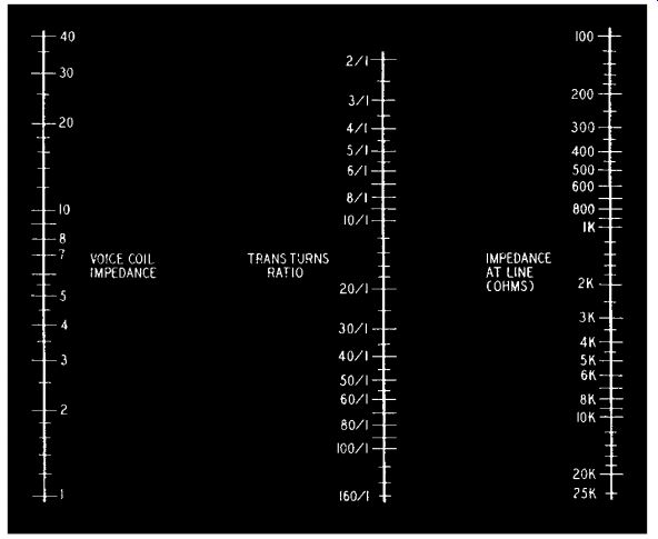
Fig. 508. A chart for obtaining line impedance from turns ratio.
A nominal line voltage is chosen, usually 70 or 100 volts. This forms the basis of all the calculations. This does not mean that there is always a signal of 70 or 100 volts, because it naturally fluctuates, as audio signal always does. The stated voltage represents a nominal maximum output level. Perhaps the easiest way to get the idea is to think in terms of a sine-wave signal, fully loading the amplifier. The amplifier then can be regarded as providing a constant voltage for all the speakers connected to the line, just as an electric line does for all the appliances connected to it. The generator at the power station has a certain maximum load capacity, and consumers' loads may be connected until that capacity is reached, the power taken by each depending on its load impedance and the line voltage. We are quite used to referring to electric lamps and other appliances as, "110-volt, 40-watt," but the same method of rating speakers may seem strange at first.
As we have seen, each speaker is fitted with a transformer to match its voice-coil impedance up to an impedance which accepts the desired wattage when the nominal voltage is applied. Some speakers may be fitted with multi-ratio transformers so their power rating can be adjusted. This makes an installation very versatile, and avoids the loss of power caused when an individual volume control is used on each speaker. You simply vary the number of watts accepted by the speaker.
Different voice-coil impedances are also taken care of by the speaker matching transformer. You can use the technique previously described for multiple speaker connections or the charts in Fig. 507 and Fig. 508.
Fig. 509 is another sample problem. The output transformers for speaker 1 and speaker 2 each have an impedance of 5,000 ohms, so they will accept 2 watts each at 100 volts. (Use the chart of Fig. 507.) Speaker 3 has a voice-coil impedance of 2 ohms, and uses a transformer of ratio 70 to 1. From the chart of Fig. 508 this gives an impedance of almost 10,000 ohms, which from the other chart (Fig. 507) rates at 1 watt for 100 volts. The total wattage load is 2 + 2 + 1 = 5. Using the chart in Fig. 507 again, this corresponds to an impedance of 2,000 ohms (still for 100 volts). So an amplifier to supply just this load would need to supply 5 watts matched into 2,000 ohms.
A large amplifier may be used to supply a load smaller than its own output. For example, suppose a 60-watt amplifier is used to feed the foregoing case requiring only 5 watts. The nominal voltage is used to calculate both speaker and amplifier output impedances. A 60-watt output for 100-volt operation should be matched into 170 ohms. The load actually connected is 2,000 ohms. Some amplifiers working into a light load like this will be unstable. To prevent this, a resistance load may be added to absorb the surplus power. In the example suggested, a resistance load to absorb 50 watts would be adequate, and from the chart the value required is 200 ohms. If the amplifier were to be operated continuously at maximum output, this resistor should have a dissipation rating of 50 watts, but in practice a much smaller (10- or 20 watt) resistor could be used.
Sometimes the reverse of the previous problem arises. The nominal load connected exceeds the power output of the amplifier. Here matters are adjusted by a different method. Suppose the load is made up of a number of speakers rated at 2 and 5 watts for 100-volt line, adding up to a total load of 80 watts. The load impedance of 80 watts worth of speakers will be 125 ohms. The load for a 20-watt amplifier, 100-volt working, would be 500 ohms. Applying a 125-ohm load to the output of an amplifier designed for 500 ohms would probably cut the output down to about 5 watts, and as well likely cause distortion. So the output must be matched to the actual speaker load of 125 ohms, which, according to the chart of Fig. 507, will give 20 watts at 50 volts, instead of the original basis of calculation, 100 volts. This means the nominal 2-watt speakers, of 5,000 ohms impedance, will get 1/2 watt, and the nominal 5-watt speakers, of 2,000 ohms impedance, will get 1-1/4 watts. Note that this is a reduction of only 6 db, so quite a useful volume will be available, although the amplifier is smaller than one planned for 100 volts. Anyway, if the four-to-one mismatch were used, giving only 5 watts or so, there would be loss of another 6 db, and probably considerable distortion.
Use of the constant-voltage system does not necessarily mean special speaker transformers must be used, so a word about picking suitable transformers from stock lines is needed. Makers of speaker transformers mark them variously in turns ratio or impedance ratio. In the former case the chart of Fig. 508 enables the correct turns ratio to be found, but the actual turns on each winding must suit the job too. A mike-to-line transformer for a ribbon microphone may have the same ratio of turns as a speaker transformer, but this does not mean that either would do the other's job successfully. A good rule for checking the suitability of speaker transformers with an ordinary ohmmeter is that the winding resistance should be between 2% and 20%, of the impedance for which it is to be used. Less than 2% means its inductance will most likely be inadequate, and 20% or more means the windings will absorb an appreciable portion of the available audio power.
If the resistance of the voice-coil winding is too low to register on the ohmmeter scale, the resistance of the high side should be compared with its working impedance. Thus, for example, a winding intended to work at 5,000 ohms should have a resistance that lies somewhere between 100 and 1,000 ohms.
Where transformers are specified by impedance ratio--for example, 7,000 ohms to 3.5 ohms--the maker has stated the best impedance at which to work the transformer. Using these impedances, it may be expected to be well over 80% efficient (probably over 90%), and have a good response at low frequencies. But these are not the only impedances at which the transformer can work. The important thing, of course, is that that ratio of impedances hold true, so the same transformer could be used for 4000 to 2, 10,000 to 5 ohms, etc. As stated in the previous paragraph, the losses and response must be kept within bounds. If impedances more than two or three times the rated values are used, the transformer's inductance may prove inadequate. If it is used with impedances less than one-third to one-half the rated values it will become quite inefficient.
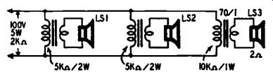
Fig. 509. A constant-voltage line, with the speakers receiving unequal
power.