VOLTAGE-REGULATED power supplies find considerable application for stabilizing high-frequency oscillators in receivers and transmitters. Their purpose is to minimize frequency drift if the line voltage varies. Less well known, but of even greater value, is the use of voltage regulators, especially gas-tube types, as hum and decoupling filters in high-fidelity audio amplifiers. They provide a highly effective and low-cost method of improving the hum level and transient response, and can transform an excellent amplifier into a superlative one.
A voltage regulator is the equivalent of a highly effective low-pass filter consisting of a series impedance A and a shunt impedance B (Fig. 601). We know from applications of Kirchoff's laws that when a current is introduced at a junction of several branches it will divide among the branches in inverse proportion to their resistances or (in the case of a.c.) their impedances. In the low-pass filter, part of the current will go through series element A and part through shunt element B. If the combined resistance or impedance of the series element and the load is 10 times greater than the impedance of the shunt element, 90% of the current will flow through B and only 10% will flow through A and the load.
In a power supply we are dealing with both d.c. and a.c. The d.c., of course, is what we want to apply to the load, while the a.c. is the ripple we want to suppress or bypass. We need a series circuit, which will offer a high impedance to the a.c. and a low resistance to the d.c., and a shunt circuit with high resistance to the d.c. and a very low impedance to the a.c. We achieve it by using either resistance or inductance for the series element and capacitance for the shunt element. The capacitor has very high resistance to d.c. and relatively low opposition to a.c., while the inductance has high impedance to a.c. and a low resistance to d.c. Thus we can bypass a good deal of the a.c. without reducing the d.c. too much. Unfortunately, it takes very bulky inductors and capacitors to do the job at hum frequencies (60 and 120 cycles). And when the hum level must be held to 60 db or more below the signal level -which means reducing the ripple to one-ten-thousandth or even one-hundred-thousandth of its value at the rectifier out put, four or five filter sections are required.
This is where the VR tube can perform a valuable service. It is an ideal hum filter, and it is very much less costly and bulky than any combination of capacitors and inductors or resistors capable of equal filtering action.
The use of VR tubes as hum filters combines perfectly with their use as decoupling filters.
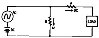
Fig. 601. Functions of series-element "A" and shunt element "B" in
low-pass filter.
Amplifier "definition"
The ideal amplifier delivers an exact counterpart of the input signal to the load. It neither adds to nor subtracts anything from the form of the signal. An amplifier may distort a signal by subtracting some of the tonal values through frequency discrimination, or by adding harmonic distortion and intermodulation. Another addition affects the definition of the amplifier.
An amplifier with good definition maintains the distinctness of the individual elements of the signal. Definition in an amplifier can be compared to resolution in a camera. A camera with good resolution will show individual blades of grass and individual hairs in a coiffure; a camera with poor resolution blurs the separate components so that they cannot be distinguished. Similarly, an amplifier with good definition reproduces the individual notes and instruments distinctly; one with poor definition will blur the individual tone elements and instruments until they cannot be distinguished separately.
Definition in an amplifier is very largely a function of transient response. An amplifier with good transient response is non-resonant, nonregenerative and non-oscillating. It is always merely a reproducer, never a generator. Unfortunately, this is much easier to stipulate than to achieve. Most amplifiers are regenerators or oscillators of the triggered type. At some point in the frequency range they are resonant, possess a feedback loop, and will break into momentary oscillation if triggered by a strong-enough impulse. These oscillations are not always audible as such in the output. They are manifested not as constant tones but as "hangover" effects, and consist of a series of echoes of the signal. They may even be pleasing to some because they give a resonant effect which sometimes simulates room resonance. But they reduce the definition of the amplifier, blurring the individual elements and instruments instead of maintaining their distinctness.
Transient oscillations
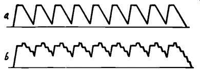
Fig. 602. (a) Original piano trill wave form. (b) Oscillations add "hangover" pulses
to each trill cycle.
Fig. 602 shows what happens. The figure at a represents the wave train of a damped (soft pedal) piano trill plotted on amplitude-time co-ordinates. There are definite valleys between the separate tones in the original signal. An oscillating or regenerative amplifier, however, will prolong each pulse with a series of spurious pulses -hangovers or echoes -which not only change the shape of the original pulse, but also fall into and partially fill the valleys between pulses. The result is indicated at b. The separation between pulses is no longer distinct and sharp, and the total effect is blurred. In fact, the effect is very much like that of playing the same trill undamped -that is, with the loud pedal depressed.
Moreover, if the amplifier is resonant at any frequency, it can be triggered into oscillation at this point by any strong transient regard less of its frequency. In good amplifiers the resonant points will be at the inaudible extremes of the frequency range and the oscillations themselves will not be audible. Nevertheless the oscillations will have two disastrous effects: first, they create intermodulation distortion; second, they are usually of much higher instantaneous amplitude than the signal and may drive one or more stages of the amplifier into the nonlinear regions of their curves and produce violent distortion of every possible form, even at low signal levels.
To be a true reproducer, an amplifier must be as nearly non-resonant, nonregenerative and non-oscillating as possible. To achieve these qualities we make the amplifier frequency response flat away below and away above the audible range (from 10 to 100,000 cycles in good amplifiers). We also try to eliminate or reduce the bad effects of feed back loops in the amplifier.
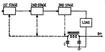
Fig. 603. Possible feedback loops in amplifier with one B supply and
no decoupling.
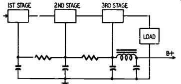
Fig 604. R-c decoupling networks in three stage amplifier.
Feedback loops are inescapable in any amplifier when several stages are fed from the same power supply. Fig. 603 is a block diagram of a three-stage audio amplifier with a common power supply and no decoupling filters. The dashed lines are the feedback loops created by the common plate-supply line. If capacitor C does not bypass all audio voltage on the line to ground, part of the audio voltage in the output stage will be fed back to the first and second stages. Regeneration will occur where the feedback is in phase with the stage signal, and oscillation will start if the amplifier has a resonant point.
With 3 resistance-coupled stages or 2 transformer-coupled stages the feedback will always be in phase over some portion of the frequency range. To minimize feedback we must insert low-pass filters in the feedback loops-filters which will pass the d.c. plate currents but will bypass most if not all of the signal frequencies. Typical R-C decoupling networks are shown in Fig 604. These will reduce feedback, at normal frequencies; but adequate bypassing below 50 cycles calls for enormous values of shunt capacitance. For this reason cheap amplifiers cut off the low-frequency response very sharply at about 100 cycles.
But as we have already noted, really high-fidelity amplifiers must be designed for a pass-band from 10 to 100,000 cycles. How are we going to decouple effectively at a frequency as low as 10 cycles? One way is to use two or more power supplies. Some expensive amplifiers actually do this. A much simpler and equally effective device, is to use one or more VR tubes at appropriate points in the power-supply loop.
VR decoupling
Any regulator which holds a d.c. voltage absolutely constant, is a perfect bypass for a.c. As a shunt unit a VR tube is effective down to subaudible frequencies. The installation of VR tubes for decoupling and hum filtering is simple and inexpensive. Only one VR tube is necessary in most amplifiers. The need for decoupling and hum filtering is progressive; we need much less attenuation of hum and feed back in the final stages of an amplifier than in the input stages. By combining brute-force inductance-capacitance filters with a single VR tube we can usually achieve almost complete hum and feedback suppression in amplifiers of five or even six stages (assuming that the final stage and the drivers are push-pull and that no interstage transformers are used). The most effective point for a VR tube is the input stage, or the preamplifier for a low-level phono pickup. Fig. 605 shows how to use a VR tube with a G-E-type preamplifier. If a commercial amplifier is used, the 10,000-ohm resistor and VR tube can be inserted at the B plus-input point. If the preamp is home-built, the 16-uf filter capacitors and 33,000-ohm series resistors can be eliminated. In any case, the 150,000-ohm resistor in the frequency-correction network can be removed. This resistor limits the bass compensation at very low frequencies to guard against motorboating. With the much better decoupling provided by the VR tube, this limitation is no longer necessary, and removing the resistor extends the effective range of the bass boost circuit.
Application to any other input circuit is just as simple. The VR tube is simply inserted in the B plus line in place of the usual decoupling network. The stage in which the VR tube is connected should be designed for a plate supply of 150 volts. Most amplifiers designed for a 250-volt plate supply will work all right with a 150-volt supply.
In any case, the improved decoupling extends the low-frequency limit and a larger cathode bypass capacitor (at least 25 uf), and a larger grid coupling capacitor should be installed. In all cases the series resistor R should be adjusted so that a minimum current of 10 ma flows through the VR tube. VR tubes have a range of 6 to 30-40 ma. Adjust R so that the VR's are as close to the center of this range as you can get.
R can then be replaced with a fixed resistor. Two or more stages may be fed by one VR tube provided the total current does not exceed 30 or 40 ma.
The addition of a VR circuit to a well-designed audio amplifier with a very wide, flat frequency range will produce a marked improvement in transient response, especially at very low frequencies. Audio amplifiers using Class AB pentodes and beam power output tubes require a regulated screen voltage for maximum output. This can be supplied by one or more VR tubes operated in series. Use tubes whose total operating voltages equal or approximate the required screen operating voltage. The OB3 operates at 90 volts, the OB2 and 0C3 at 105 volts, and the 0A2 and OD3 operate at 150 volts. The VR-75 (obsolete but often available on the surplus market) supplies 75 volts.
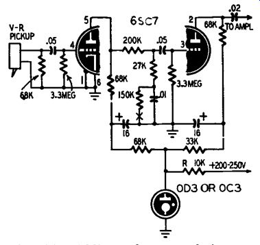
Fig. 605. Adding voltage regulation to a variable-reluctance pickup
preamplifier.
You must observe some precautions when using VR tubes. They can oscillate if shunted by a leaky capacitor or an R-C network. The VR tube must light or it will not regulate. VR tubes are light sensitive and will have less voltage across them in a bright light than in the dark. This is not serious. In a sense, your VR tube is like a bleeder. The amount of current drawn by the VR must be supplied by the power transformer and passed by the rectifier. Take this factor into consideration in your power supply design.