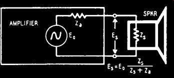
WHEN an audio amplifier drives a speaker system, there are two impedances which affect the performance. The first (Zs in Fig. 801) is the impedance of the speaker. Techniques for measurement of speaker impedance were described in the preceding Section. The second impedance we must consider is the internal impedance of the amplifier (Z. in Fig. 801). The voltage across the speaker is not the full voltage of the amplifier (E0) because the internal impedance of the amplifier is in series with the speaker. If the amplifier's internal impedance is big enough to be significant and if the speaker impedance varies with the frequency, the voltage across the speaker will not be uniform at all frequencies but will have peaks at the impedance peaks in the speaker. The voltage across the speaker will differ from the fundamental voltage of the amplifier by the ratio indicated in the formula of Fig. 801. This is one reason why an audio amplifier should have a low internal impedance.

Fig. 801. Basic amplifier impedance circuit.
The damping factor
The internal impedance of an amplifier may be measured at any one of the amplifier's output taps. A more useful unit is the damping factor, which is equal to the rated output impedance divided by actual internal impedance. This makes it unnecessary to state at which out put taps the measurements were made. The internal impedance is not a constant value but depends on the frequency at which it is measured.
The complete description of an amplifier's internal impedance is a curve showing the damping factor versus frequency.

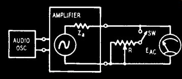
Fig. 802. Circuit for measuring impedances.
Normally an audio amplifier will have an internal impedance of 1/2 to 1/20 its rated output impedance. The damping factor will therefore be in the range of about 2 to 20. This damping factor is determined by the plate resistance of the output tubes, the circuit in which they are used, and the design of the output transformer. The use of feedback around the output stage reduces the effective internal impedance. Amplifiers with triode output tubes such as 2A3's or 6B4-G's without feedback and using traditional transformer design, have damping factors of 2 to 3. Feedback will increase the damping factor. Beam power tubes such as the 6L6 give an amplifier a very high internal impedance. Feedback is essential with these types, and their high gain makes considerable feedback feasible.
There are several ways of measuring electrical impedance. Many of them require bridge circuits or that hard-to-find item, an a.c. milliammeter. The methods to be described have been limited to the simplest equipment possible. An audio oscillator is needed as well as an a.c. voltmeter, a couple of rheostats of about 10 and 25 ohms and a few 10-watt resistors between 10 and 50 ohms. The oscillator should be capable of covering the audio range in which you are interested and should have reasonably low distortion. The voltmeter is preferably of the electronic type, though good results can be obtained with a sensitive volt-ohm-milliammeter with a.c. scales in the 0.5- to 3.0-volt range. Just remember to make all measurements on the same scale if your meter isn't uniformly calibrated on all scales.
One of the simplest methods of measuring the internal impedance of an amplifier is to use the scheme shown in Fig. 802. The plan is to measure the output voltage with no load across the amplifier: then with an adjustable resistor as a load to find at what load resistance the output voltage will be one-half the no-load voltage. The audio oscillator is connected to the amplifier input, and an on-off switch and rheostat are connected in series to the amplifier output terminals. These should be the impedance taps used in your particular installation. The rheostat should be capable of covering a range down to about 1/20 of the nominal output impedance. The voltmeter is placed across the output taps. With the switch open, the amplifier gain or oscillator input is adjusted until a conveniently measurable voltage is obtained, say 2.0 volts. The switch is then closed and the rheostat adjusted until the voltage drops to 1.0. The switch can now be opened and the resistance of the rheostat measured. This resistance equals the internal impedance of the amplifier.
It may sometimes happen with an amplifier of very high damping factor that you cannot get down to one-half the no-load voltage with the rheostats available. In that case the internal impedance can be calculated from the following formula, using voltage readings taken at the lowest resistance setting of the rheostat.
R E() Za ER
Z. is the internal impedance of the amplifier, E0 is the no-load output voltage, ER is the voltage across the load resistance R. For example: if the open-circuit voltage at the 8-ohm tap is 2.0 volts and when the load resistance is lowered to 1.3 ohms (as far as you can go with your rheostat), the output voltage is 1.4 volts, and the internal impedance is:
1.3 X 2.0 Z. = 1.3 = 1.85 - 1.3 = 0.55 ohms 1.4
These measurements should be made at several different audio frequencies until the entire audio range is covered. A good plan is to check at 20, 30, 50, 100, 1,000, 5,000, 10,000 and 15,000 cycles. If the results are about equal or change smoothly you have a good picture of the amplifier's internal impedance characteristics. If irregular results are obtained, further checking is in order.
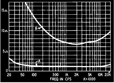
The internal impedance curves of two very different amplifiers are shown in Fig. 803. The lower curve (amplifier A) is that of the Brook 12A amplifier. This is a triode output amplifier (push-pull 2A3's), with a high-quality output transformer and with inverse feedback. The upper curve (amplifier B) is that of a home-built beam-power-tube amplifier with a lower quality output transformer and a poorly designed feedback system. However, it is typical of many published designs and of amplifiers used in home music systems.
This type of curve results when the feedback is not uniform over the entire audio range. If the frequency response of the amplifier is not quite flat without feedback, then feedback may help flatten the response, but the internal impedance of the amplifier will rise at each end of the curve. Using the feedback loop around the final stage to adjust frequency response or using it in tone control circuits can cause a lot of trouble in the matter of damping factor. Amplifier B may sound satisfactory with a narrow range speaker system but the superiority of amplifier A with a wide range system is obvious.

Fig. 803. Amplifier impedance curves.