WITH a little imagination and ingenuity mixed with a knowledge of the methods of applying the v.t.v.m, difficult problems in audio measurements can be solved.
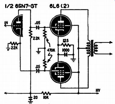
Fig. 901. Idealized a.f. phase inverter.
The modern v.t.v.m. measures both a.c. or d.c. voltages. It requires essentially no power from the circuit to which it is connected, thus enabling measurement of true r.m.s. voltages in high-impedance circuits and true d.c. voltages in complicated series circuits.
Fig. 901 illustrates a typical phase inverter and output stage as found in many amplifiers. The v.t.v.m. can be used to check the balance of the audio voltages applied to the output-tube grids. In this circuit it is particularly important that the value of the cathode resistor and the plate load resistor in the phase inverter stage be identical.
With a constant audio signal applied to the input of the amplifier from an oscillator, the audio (a.c.) voltage appearing on one output-tube control grid should be the same as that on the other output tube's control grid. If the voltages from each grid to chassis differ by more than a few percent, the quality of the amplifier will be seriously impaired.
There are several possible causes of unbalance in the circuit shown.
Values of the grid resistors in the output stage should be the same.
They should be checked with an ohmmeter and replacements selected which match in value. The value of the coupling capacitor in series with each output grid will affect the balance at low audio frequencies.
For best results, these should be the same. The capacitance of the coupling capacitor is chosen to have negligible reactance at the lowest frequency the amplifier is required to reproduce. The .05-0 capacitors in Fig. 901 have a reactance of approximately 31,850 ohms at 100 cycles per second.
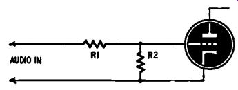
Fig. 902. R1 indicates coupling reactance.
At any given frequency of operation the capacitor can be considered a resistor in series with the grid resistance. The reactance of the capacitor is thus indicated as R1 in Fig. 902. The grid resistor is R2. This simplified diagram shows how the reactance of the capacitor forms a voltage-dividing network, with the grid resistor as the output portion.
Since the reactance of a capacitor varies inversely with frequency, it can be seen that the voltage at the grid of the tube would suffer if the capacitor value were too low and its reactance high at the lower frequencies of operation.
Coupling and bypass capacitors
The effectiveness of the coupling capacitor at all frequencies of operation can be measured with the v.t.v.m. Connect an audio oscillator to the input of the amplifier and measure the audio voltage to chassis on both sides, the input and output sides, of the coupling capacitor. Write down the voltages measured on each side, using different audio frequencies from the audio oscillator. As the frequency is made lower and lower, the difference between the voltages measured on the input and output sides of the capacitor will become greater. The low frequency response of the amplifier can be improved, of course, by using bigger coupling capacitors.
If the coupling capacitor is leaky and permits d.c. to pass, the v.t.v.m. will detect it. Set it up to measure d.c. and connect it to the output side of the coupling capacitor. With the following tube removed, there should be no d.c. present unless the capacitor is defective. Replacement coupling capacitors should be high quality mica, ceramic or paper dielectric, with a voltage rating several times that of the d.c. on the plate of the preceding tube.
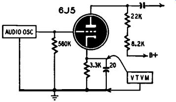
Fig. 903. V.t.v.m. checks cathode bypass.
The effectiveness of bypass capacitors can be checked simply with the v.t.v.m. and an audio oscillator. With the oscillator connected as shown in Fig. 903, from grid to chassis (adjusted to an output voltage less than the d.c. bias on the grid) and the v.t.v.m. across the cathode bypass capacitor, no audio voltage should be indicated. This test should be conducted at the lowest frequency the amplifier is expected to reproduce. If audio voltage is shown, the stage will be degenerative at that frequency and all lower frequencies. To improve the low frequency response, replace the bypass with a larger one. The reactance of a 20-uf capacitor at 100 cycles is 80 ohms. Since this is small compared with the value of the cathode resistor, 3,300 ohms, the amplifier's response at 100 cycles should be good.
Measuring amplifier gain
The gain of an amplifier is easily measured with the v.t.v.m. The input power and output power as measured by it are converted to decibels of gain. Set up the amplifier as shown in Fig. 904 with resistors to simulate the input and output devices. Adjust the volume control for maximum gain. If the resistor in the input is intended to simulate the internal impedance of a dynamic microphone it will be approximately 25,000 ohms. (It is best to get exact data on the internal impedance of a microphone or pickup from the manufacturer.) Adjust the output of the audio oscillator to one volt as indicated by the v.t.v.m. The input power is then found by the formula: W = E2 /R. Since the voltage is 1, E^2 is 1 x 1 or 1. Dividing by 25,000 gives an input power of .00004 watts. For convenience, this might be called .04 milliwatt.
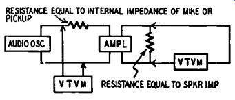
Fig. 904. This block diagram indicates the technique to be followed
for measuring the gain of an audio-frequency amplifier. Al though two
v.t.v.m.'s are shown, a single meter can be used with a d.p.d.t. switch.
Supposing the output load resistor is made equal to a speaker impedance of 8 ohms, the output power can be computed in the same way. If the v.t.v.m. reads 13 volts across the 8 ohms, the power output is 13 X 13 (or 169) divided by 8. This gives 21 watts output.
The output power divided by the input power is the power ratio and will give the gain of the amplifier in decibels by the formula: db -= 10 log10 X power ratio.
A decibel chart
Rather than go to the trouble of finding the log and working this out the hard way, the chart of Fig. 905 is supplied to make it simple.
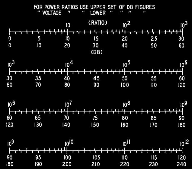
Fig. 905. This chart simplifies conversion of power and voltage ratios
to decibels.
Locate the power ratio on the upper scale and read below it the gain in db. For power ratios, read the upper set of db figures. For the example we have chosen, the power ratio is 21 divided by .00004, or 525,000 to 1. Find 525,000 on the upper second scale and read below it approximately 57.3 db. The gain of the amplifier is 57.3 db.
If the amplifier has the same impedance at both input and output, such as the 600 ohms used commonly in line amplifiers, the task of determining gain is considerably simpler. The gain of such an amplifier can be figured from the ratio of the voltages appearing across the input and output without converting to power ratios. Using the same setup as shown in Fig. 904, measure the two voltages. Divide the larger voltage by the smaller one. This data can be used to determine gain by the formula: db = 20 log10 X voltage ratio.
Again, instead of working it out, refer to Fig. 905. Using the lower set of db figures, read the gain opposite the voltage ratio. For example, if the voltage across the input is 1 volt and the voltage across the out put is 200, the voltage ratio is 200/1 or 200. Locating this ratio in the chart will show a gain of 46 db opposite the ratio.
The over-all fidelity of the amplifier can be measured by plotting the gain as measured by these methods at a number of frequencies. For example, plot the gain at:
100 cycles | 1,000 cycles | 7,000 cycles
300 1,500 10,000
500 3,000 15,000
700 5,000 20,000
The variations in gain in db with reference to the gain at 1,000 cycles indicate the over-all fidelity of the amplifier.