SERIOUS audio design dates back about three decades. At that time the design of audio circuits was in the stage of breaking away from being just part of a radio receiver or transmitter.
Specialists were beginning to make audio amplifiers for phono graphs and public-address systems. Fidelity was, of course, nothing to be compared with modern possibilities and the early methods of "development" would be frowned upon by present engineering standards.
In those days there was little more to choose from in the way of tubes than a few battery-operated triode types of varying impedance, or mu-according to which term of reference you may prefer. Most of the people "in the business" were virtually hobbyists and the kit radio, to construct at home, was very popular.
The radio sets of about that time contained a great many triode tubes; a number of tuned circuits at radio frequency, followed by an "audio amplifier" consisting of a number of tubes and inter stage transformers to get enough amplification to give an audible level from the comparatively feeble transmitters then operating.
Early advances
Then the screen-grid tube or tetrode first made its appearance and shortly afterward the pentode. These came as an innovation and were hailed as producing fabulous results. Now you could get "much more power" from the sets. "It gave real punch" and similar rather nonscientific terms were used.

----------
Some, however, noticed that the triode, while it did not give quite so much output, gave cleaner reproduction. The pentode gave more "punch" but at the expense of quality. There was some distortion which the triode did not give. Some interstage transformers behaved much better than others in this regard too.
And thus the quest for improved quality in audio began. Non linear distortion is, largely, a function of how much headroom you have. That is, if you want to listen to 5 watts of audio power, the peaks may run up to 25 or 50 watts. So an amplifier of this handling capacity must be used to avoid distortion. This explains the quest for larger output stages with good performance to achieve clean output.
Push-pull operation reduces second-harmonic distortion which, in those days, was the major variety. It also enables the output transformer to be designed much more easily and with improved performance. But this created a problem-a phase inverter is necessary, unless you use push-pull operation from the beginning to the end of the amplifier. Some designers of those days favored this arrangement.
In the early days of reproduction from phonograph records some kind of tone control may have been used, but professional equalization was not visualized. Rather, adjustments were made until the program material just sounded nice.
How confusion arose
A great variety of people, working at almost an equal variety of technical levels, have achieved vast progress since those days. But some of these people have been working in ways that have con fused the score for the uninitiated.
For one example, this writer knew some English "engineers" whose principal hope of fame then rested in acquiring copies of American magazines and finding clever ideas to apply in audio circuits. If nothing appropriate could be found in magazine articles, these individuals would start scribbling on paper or try connecting components in different places in actual circuits, in an endeavor to do "something clever." The desire to do something clever still persists, under the impression that a clever circuit will gain an edge on one's competitors.

-------------------
While some followed this method, many workers in the field concentrated on getting something which works practically, with out their knowing quite why. Yet others went overboard in the theoretical direction and hired mathematicians to take care of the theory. This writer remembers one instance where the design of an acoustic horn for a loudspeaker was being investigated .
The mathematician hired for the purpose spent days going through involved mathematical functions and eventually came up with the solution: that the particular horn design in question had a negative acoustic resistance. To the mathematician this statement apparently had little meaning. But, to the practical engineer who heard it, it seemed as if we had struck across an acoustic form of perpetual motion-because a negative resistance must in essence be a generator! The only kinds of negative resistance realized in practice re quire a B-plus supply-and usually filament as well-to provide the necessary energy for the generator. A negative acoustic resistance, therefore, should oscillate, all by itself, without any input.
This would be very convenient because, by appropriate matching, one could make a horn loudspeaker with an overall efficiency exceeding 100%! Of course, somewhere during those days of figuring, the mathematician had made a mistake! Those panaceas But in audio literature the trend to look for the "ultimate," or perfection, or some special trick which will prove to be a panacea for all audio troubles, has persisted. As an example, the cathode follower was once hailed as being the answer to all audio problems. It provides a high input source resistance, multiplying the natural input characteristics of the tube by its operating gain.
It provides a low output source resistance which is very helpful for many purposes. It also operates at negligible distortion.
However, if you regard the cathode follower as a matching device to provide a low output source for matching into a low load, it definitely doesn't do all of these things at the same time.
It may provide the low output source very nicely, but connecting the low value load to it removes all the feedback that you thought you had and thereby destroys its effectiveness in the other spheres just mentioned.
You never get something for nothing, not even in audio circuitry. In this example, the cathode follower provides impedance transformation and distortion reduction. If you take advantage of the impedance transformation for matching purposes, the distortion reduction disappears. If you take advantage of the distortion reduction and a convenient low source impedance, then you cannot utilize its matching property by connecting a low value load to it.

--------
Reaching the ultimate
An aspect of this philosophy of trying to do something that achieves the "ultimate" in audio can be illustrated by the use of positive and negative feedback. The development of this method arose due to the large loss of gain that is necessary, with negative feedback, to achieve a great amount of improvement in performance.
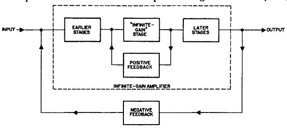
To reduce distortion by a factor of 100 to 1 it is necessary to use 40-db feedback. This in turn means that 40 db of gain must be thrown away. Then it was discovered that the gain could be increased artificially, as well as being reduced, by the use of positive feedback, rather like regeneration in radio. So, by using positive feedback over a small section of the amplifier, the gain could be increased. Then negative feedback could be employed over the whole amplifier to achieve an improved reduction in distortion as illustrated in Fig. 101.
A "logical" ultimate to this would appear to be the condition where positive feedback is used to provide a gain of infinity. This occurs when the signal fed back over the small section of amplifier is exactly equal to the original input. This means that the overall amplifier to which negative feedback is applied will also have infinite gain.

Fig. 101. Two-loop feedback amplifier, showing attainment of "infinite
feedback."
So it would seem that we should come out with zero distortion and a perfectly flat frequency response because now the use of any feedback at all becomes infinite feedback.
Have we at last found a way of getting "something for nothing"? It might appear so, until we realize that the question of which feedback loop is the outer one depends upon viewpoint.
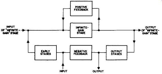
We can redraw the circuit of Fig. 101 as at Fig. 102, showing the same block elements.
Here it appears that the rest of the amplifier and the negative feedback loop can be regarded as an alternative feedback path over the single stage, in parallel with the positive feedback. This means that application of negative feedback destroys the infinite gain property of this stage.
In reality the stage can be rendered stable again after positive feedback has made it oscillate, merely by connecting the overall negative feedback. In the section on feedback more examples of this kind of interaction will be considered and the subject will be discussed in full to show how feedback can affect performance.
It is introduced at this point merely as an illustration of the kind of misleading presentation that has been made from time to time.
The implication the reader draws is of an ultimate achievement that will revolutionize audio.
Confusion compounded
The purpose of this guide is, not to go into the details of design in the various stages of audio circuits, but rather to answer the question ""What's the score?" So many methods have been introduced, in almost every section of audio, that the uninitiated finds himself confused. This confusion has, in fact, very often affected the engineer's approach to his problem through no fault of his.

Fig. 102. Block diagram of Fig. 101 in rearranged form.
To illustrate, a difference is sometimes noted between the performance of two circuits or amplifiers which is the opposite of that anticipated. A circuit which, according to measurements and design, should give better performance than another, is observed to bear the opposite relationship-the inferior circuit sounds better. Maybe it's an ultra-linear output circuit that, according to measurements and theory, should give a superior performance to either a triode or pentode-type output circuit. However, why should a particular tryout seem to show the opposite? This improved performance is dependent upon the ultra-linear transformer behaving correctly at all frequencies throughout the audio band. A practical transformer may behave perfectly at all frequencies used for test purposes and yet introduce spurious effects on program material. This is not a direct reflection on the ultra-linear circuit; it is something that did not occur in either the triode or pentode circuit. So it is possible that a particular ultra-linear circuit may sound inferior to either of the older circuits, although, according to theory, it is supposed to be superior.
This does not invalidate the theory; it merely shows that all the facts have not been taken into account. But the uninitiated inevitably would judge the ultra-linear circuit adversely. This happens time and again in audio.
Often this kind of misjudgment has given the engineer additional problems because he has to satisfy the people who evaluate his work (whether this is the ultimate public or just the people who employ him) and these people are apt to believe their ears and completely disregard the engineer's theorizing! There is an opposite philosophy the designer has had to con tend with too: the continual strife for better specifications. This approach reverses the procedure and puts the theoretical specifications ahead of practical performance.
The endeavor for improved performance initially showed that the flatter the frequency response the better an amplifier would sound. Furthermore, the wider the frequency response extended, at least up to the full width of the audio band, the better the amplifier sounded.
Also an amplifier with only 5% distortion sounds considerably better than one with 10%, This being the case, the natural endeavor was to improve the bandwidth and flatness of the response and to reduce the distortion as indicated by measuring equipment.
In the specifications of the amplifier, however, this process has been taken to extremes. Measurements have been made from time to time to determine just how much deviation in frequency response, and also how much distortion, the ear can detect. Most modern high-fidelity amplifiers, according to measurement and specification, give distortion that is only a small fraction of the smallest that can be detected audibly.
According to this criterion then, all high-fidelity amplifiers should sound identical. In practice however they don't--even when used with the same phono, pickups, tuners and loudspeakers. The sound given by different amplifiers varies, although the difference in specification is so small as to prove the difference inaudible. What does it mean? Things happen in amplifiers that are not described in the simple technical specifications or found by the simple method of measurement. Amplifiers have ways of misbehaving that do not show up under conventional measurement methods and it is this misbehaving that makes the difference audible.
In this guide, as well as discussing the features of the varieties of circuits available for each purpose that contribute different results-in terms of standard specifications and performance--we shall also endeavor to give details and descriptions of the things that can happen in the circuit that do not get described by these technical specifications. In this way we will give a more complete picture of the relative merits of circuits so that the reader may decide for himself at each stage which is the best circuit for his particular purpose.
The section arrangement may seem unusual. The philosophy behind its arrangement is intended to follow the theme set here.
The first big problem in getting good sound is a satisfactory out put stage. So we start there and work our way through the progressive obstacles to the approach to an "ultimate" in high fidelity.
In reading this guide, nowhere will you find a direct statement that such and such is the best kind of amplifier-or even the best circuit for this part of an amplifier. In the complications of audio circuitry, no such unequivocal statement is possible. Every circuit will have its advantages and its disadvantages. The determination of which is the best circuit for an individual purpose will depend entirely on the relative importance of the various advantages and disadvantages for the particular job in hand.
To aid in seeing, at a glance, the relative characteristics of the circuits considered, several of the sections conclude with a tabulation of the merits and demerits of the varieties considered in that section.
The guide does not stop at circuits, because these are not all there is to audio. We listen to sound waves, not electrical impulses. So a complete consideration of the best in audio must consider every link from the original sound to the listener's ears.
Also see: Pre-stereo (Monophonic) High-Fidelity Audio: Design, Measurements and Construction