A DECADE or so before this guide was written, the score in this part of audio circuits would have been a simple one to discuss. However it was nonetheless strongly debated. The choice was then a simple one, between triode or pentode operation of the output tubes.
Some contenders were in favor of what might be termed brute force operation, using "enough triode" to get the required avail able output. The feature stressed about triode output was that, although it was less efficient than the pentode output stage, it was inherently lower in distortion.
The contenders for the pentode output stage pointed to the higher efficiency of this kind of tube and showed that the same number of watts could be achieved at considerably lower cost.
They also maintained that pentode distortion is no higher, and sometimes lower, than that of triodes.
Both sides had their points, which is largely why the variety of circuits we shall discuss in this section came into being-in an endeavor to achieve the advantages of both. Today so many different output stages are available and the claims put forward for them are so difficult to reconcile one with another that many, engineers even, are confused as to their relative merits and the essential features of each.
To get a clear picture, the best method is to take a particular pair of output tubes, such as the 5881 (about which we have plenty of data) and compare their operation in the various circuits possible. Other tube types may vary slightly the relative merits of circuits using them but, in general, different tubes will just alter the magnitude of output.
As far as available power and basic distortion are concerned we need only to consider three methods of operation: triode, tetrode (or pentode) and ultra-linear. The other variations in this section can easily be derived from one or more of these modes of operation by using partial or full cathode-follower action or some other rearrangement of the circuit in which the tube is used.
There is another variant that needs consideration: the kind of power supplies used, particularly for the bias. The way the amplifier behaves on transient loud passages, compared with sustained passages, often depends on the design of the tube supplies. These incorporate large capacitors. For a short burst of power, the capacitors will not have time to discharge appreciably so the power delivered will have the same supply voltage to draw from as at low power. But for a sustained passage, the increased plate current will cause the plate supply voltage to drop gradually. In a well-designed amplifier, two things are necessary for uniformly good handling of program material:
a) The changes in supply voltages that occur due to level increase must not appreciably affect either the distortion or gain of the amplifier. Should they do so, the initial part of a loud passage will sound different from its "follow through."
b) The changes must be arranged to occur at a uniform rate so that no peculiar effects arise in transition. All the supply voltages (screen, plate and bias) must have the same time constant.
Whatever circuit is used, the plate current of an output stage increases with signal level. This means the supply voltage will drop, unless special arrangements are made for good regulation which are usually not economic. At the same time the bias voltage increases: in the case of automatic bias, due to increased plate current through the bias resistor; in the case of fixed bias, due to grid current when clipping occurs.
Careful design will allow a circuit using automatic bias to fulfill both the conditions described, but fixed bias presents problems that often are not satisfactorily solved for program presentation. ·when clipping occurs, the negative bias is increased due to grid current pulses. The bias supply has a relatively long time constant to smooth out ripple in a "no-current" circuit. So when clipping ceases, the increased negative bias stays longer than the change in plate voltage.
Fixed bias will generally get a larger maximum output from a given pair of tubes by allowing more favorable operating conditions to be used. This real increase in output may not always be apparent. To compare maximum output, volume is usually turned up to see "how much it will give." So clipping will occur in each amplifier. ·with fixed bias, erratic changes of bias occur that cause distortion not present when the level is kept within the limit.
With with automatic bias, the change is only evident for the duration of the clipping, which is audibly more acceptable. Thus it happens that the listener will often conclude that the automatic bias amplifier gives a bigger output than the one with fixed bias, al though measurements show the reverse.
Push-pull triodes
Fig. 201 shows the circuit for push-pull triode operation with fixed bias. This requires a separate bias supply but has the ad vantage that a greater output is available from the pair of tubes.
Fig. 202 illustrates the composite tube characteristics for a pair of 5881's operated in this manner, using a plate supply of 400 volts and -45 volts of fixed bias. Shown dashed are the individual characteristics of each tube, while the solid lines joining the dashed curves indicate the composite characteristics of the tubes operating in push-pull.
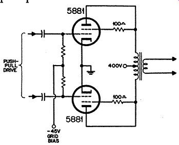
Fig. 201. Circuit for pair of 5881 tubes operating in push-pull as triodes
with fixed bias.
The central solid load line represents the optimum load condition--a plate-to-plate load of 4,000 ohms. This operating condition yields an output of 13.3 watts with 4.4% distortion which analyzes into about 4% third harmonic and 1.5% fifth.
The 4,000-ohm plate-to-plate load line is somewhat of an ideal.
It is the condition under which amplifiers are usually measured but unfortunately they do not normally work under this ideal.
Fig. 203 shows two sets of curves for triode operation.
The load resistance may vary, either above or below 4,000 ohms, and, what is worse, it often contains additionally some reactance.
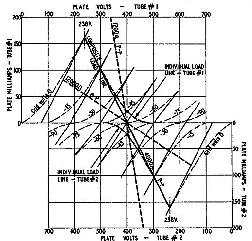
Fig. 202. Composite curves for the working conditions shown in Figure
201. The sig11ificance of the various dashed lines is explained in the
text.
One pair shows the variation in distortion at maximum power and also the variation in the maximum power available before clipping occurs. A resistance load value is used in all cases, but its value is varied between 0.3 and 3 times the optimum value of 4,000 ohms plate to plate. These limits are represented by the dashed lines in Fig. 202.
But practical loads for amplifiers, which are usually speakers, with or without crossover networks, also incorporate reactances which cause the load line to become elliptical as represented in Fig. 204. The other pair of curves in Fig. 203 shows the variation in distortion at maximum power and the maximum power before clipping occurs under a hypothetical load condition made up as follows: a basic resistance load of 4,000 ohms plate-to-plate to which reactance is added. In one direction a shunt reactance de creases the load impedance as far as 0.3 of the 4,000 ohm plate-to plate optimum and in the other direction a series reactance increases the total load impedance up to 3 times its optimum value.
When these curves are compared with the corresponding ones (given in Fig. 208) for pentode operation, it will be easy to see why the triode type output was preferred.
These curves have all been taken for push-pull operation with fixed bias. Sometimes, for economy in circuit design, automatic bias is used with the circuit of Fig. 205. Fixed bias is preferable because the combined plate current fluctuates with the signal.
With 45-volts bias and no signal the plate current is 65 milli-amperes, but when the output is driven to the full length of the load line, the current rises to 130 milliamperes.
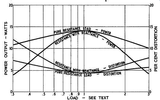
Fig. 203. Output characteristics for push-pull triode operation as loading
is varied.
Suppose the bias had been obtained by the automatic bias circuit of Fig. 205. Then at the zero-signal condition a current of 65 ma would need to be fed through a resistor of about 700 ohms to produce about 45 volts; at maximum-signal condition the current of 130 ma would need to be fed through a resistor of only 350 ohms to produce a drop of approximately 45 volts. If a resistor of 700 ohms is used, then under maximum-signal condition the bias would rise to 90 volts. This would result in distortion due to the tubes being driven back beyond cutoff. On the other hand, if a resistor of 350 ohms were used, the bias at zero-signal condition would only be 22.5 volts. This would result in over heating the tubes when there is no signal or during quiet passages.
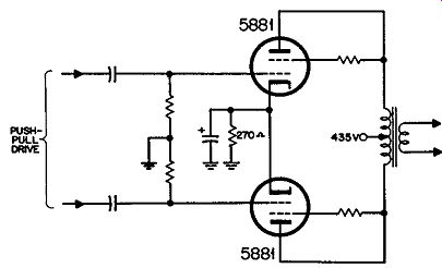
Fig. 205. Circuit for pair of 5881 tubes operating in push-pull as triodes
with automatic bias.
A self-bias circuit must choose a different operating condition for the tube, such that the plate current does not change quite reactance combined with the original resistance.
A further complication arises from the fact that in an automatic bias circuit, the bias voltage is subtracted from the total B-plus supply. This means that, if the bias swings from 30 to 60 volts and the B-plus supply is 440 volts, the plate-to-cathode voltage will swing from 410 to 380.
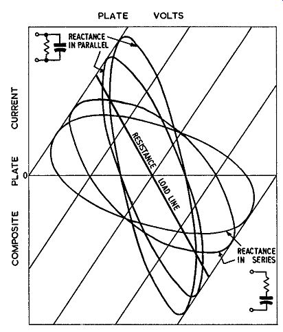
Fig. 204. Construction of a load line representing so much from zero
to maximum signal. A typical condition for self-bias operation of 5881's
as triodes is: 400 volts plate-to-cathode; 35 volts bias (supply= 435
volts); plate current 130 ma; bias resistor 270 ohms; plate-to-plate
load 8,000 ohms; power output 8.2 watts at 5% distortion, mostly low
order third.
No mention has been made of "class" of operation: class A, class B, class AB, etc. When these terms were first used, they provided a ready means of distinguishing between different operating conditions. Soon after they were introduced it became necessary to add subscripts to indicate how far the tubes were driven in the opposite direction. Thus class AB1 would indicate that the tubes are so biased that for small signals the operation is class A-essentially linear on both tubes--while for maximum signal each tube is cut off for part of the cycle and that the tubes are not driven into the positive grid region to get maximum output.
What was not appreciated until later was the fact that changing the operating condition permitted changes in the fundamental concept of load matching: a triode could be matched into a load approximately equal to its plate resistance instead of several times higher. But a closer examination of the load line shows that this change, made to tubes set up for class-A operation, results in the same bias point yielding class AB operation. So now, to describe completely the class of operation, we need to specify what the loading does as well as the relative operating bias. The "simplified" designation has become as complicated as the details it is intended to replace. So we believe the best information can now be given in terms of operating voltages, currents and loading values.
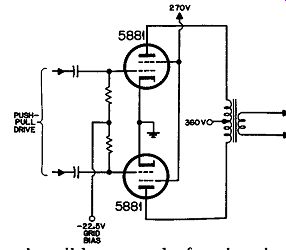
Fig. 206. Circuit for pair of 5881 tubes operating as pentodes with
fixed bias.
Tetrode or pentode
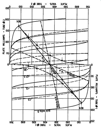
Fig. 207. Composite curves for the working conditions shown in Fig.
206.
Turning now to tetrode or pentode operation, the circuit is shown in Fig. 206 and the composite load condition in Fig. 207, using a screen voltage of 270 with a plate voltage of 360. These are the conditions quoted in the tube manual. A plate voltage of 400 could be used, which would emphasize still further the difference in available power between triode and pentode operation.
Using the quoted plate-to-plate resistance of 6,600 ohms, the power output is 26.5 watts or just double that when the tubes are operated as triodes. With 400 volts on the plates it should be possible to get 35 watts from this method of operation.
The distortion quoted in the tube manual is 2%, which closely agrees with that measured in practice. However, there is an important difference to be noticed between this distortion and that produced by the triodes. Analysis of the 2% shows it to be approximately 1.7% third harmonic and 1 % seventh. The 1% seventh harmonic can contribute more annoying distortion than the 1.5% fifth harmonic present in the triode operation, because the spurious tones it causes-both harmonic and IM-are much more discordant.
When we turn to the distortion-power output characteristics of Fig. 208 however, we see something else about pentode operation. It is much more critical, not only of the load resistance used being closely in compliance with the optimum value, but distortion and maximum output are also critically dependent upon absence of reactance with a reactance shunting the resistance down to an impedance of 0.3 times optimum, the pentode gives less output than the triode arrangement although, under optimum conditions, the pentode output is about double that of the triode arrangement.
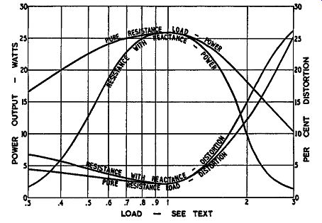
Fig. 208. Output characteristics for push-pull pentode operation as
loading is varied.
A 3-to-1 change from optimum value is by no means unusual in speaker impedance characteristics. In fact the change is often greater than this. From this it is evident that although, according to the methods used for measuring output and distortion, the pentode gives about twice the output available from triode operation, yet in practical working conditions, the triode gives just as much useful power into a speaker load as the pentode.
Ultra-linear
This is why the ultra-linear operation came into being. Using as we have, a tetrode-the 5881-to make the equivalent of either a triode or pentode, we can see that: To operate as a triode the screen, or No. 2 grid, swings with the same potential as the plate.
To operate as a pentode the No. 2 grid is kept at constant potential while the plate is allowed to swing.
Ultra-linear operation splits the difference: the screen grid swings, but by a voltage less than that of the plate. This is achieved by the use of a tapping on the primary of the output transformer, as shown in Fig. 209. Static tube characteristics for this method of operation, as published by Tung-Sol, are illustrated in Fig. 210.
These curves are obtained by changing the screen voltage in a different manner from the plate voltage to simulate the way in which the plate and screen would swing away from the operating point of 400 volts.
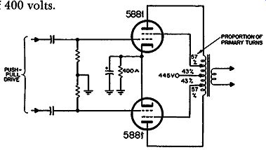
Fig. 209. Circuit for pair of 5881 tubes operating in ultra linear arrangement.
With the ultra-linear circuit, the change of total plate current with amount of drive is not so great as with other methods of operation. With this particular tube, there is little advantage in fixed-bias operation for this reason. The operating condition for maximum drive is -45 volts. If this is obtained by automatic bias, it only drops to -40 volts in the quiescent condition. This observation does not apply to all tube types. For some it is advantageous to use fixed bias-a bigger output can be obtained within the plate dissipation rating of the tubes.
Using a plate-to-plate load of 6,500 ohms and a plate supply of 445 volts, the maximum power obtainable from a pair of 5881's in ultra-linear is 28 watts, with a distortion of about 3.3%, almost pure third. This is a very useful compromise between triode and pentode operation.
Pentode operation might give 35 watts with 400 volts on the plate-it would not be permissible to use 400 volts on the screen because the tube would be overrun. Notice the improved characteristics shown in Fig. 211. Although for wide deviations from optimum load ultra-linear operation does not hold up as well as the triode, for smaller deviations it is about as good as a triode, while it always gives better results than a pentode.
If only the optimum load condition were considered, it would appear that the triode gave the highest distortion, with 4.4%, while the pentode gave the lowest with 2%, But when deviation from optimum load, such as occurs in practice, is considered, it is found that the ultra-linear consistently gives the lowest distortion, with the triode running second and the pentode quite a poor third. It is only by the critical operation of the pentode that the low figure of 2% is obtained and then an analysis of the content of this 2% shows that it is of relatively high order.
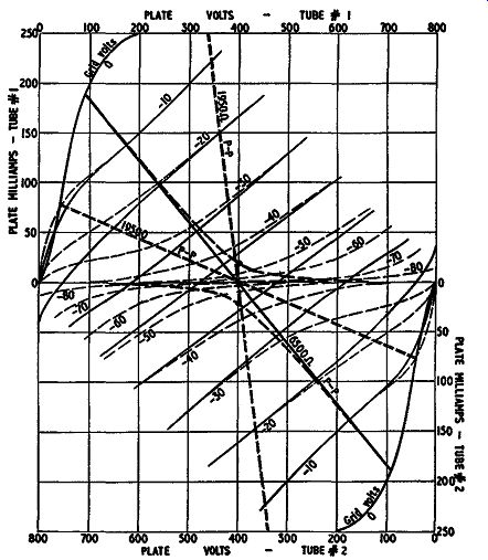
Fig. 210. Composite characteristics derived from the curves published
by Tung-Sol for 5881's in ultra-linear operation.
Grid drive
So far we have discussed only the power output and distortion of these different circuits. In designing a whole amplifier we also have to consider the voltage drive necessary at the grids to give this output. In more complicated circuits the voltage drive needed is modified by the use of partial or wholly cathode coupling.
Grid drive is specified in a number of different terms. In referring to a tabulation of tube data, take care to ascertain which value it is that is listed. Some give therms voltage per grid; some give therms voltage from grid to grid (of a push-pull stage) which is twice this value; some give the peak voltage on each grid, which is 1.414 times the rms voltage; others give the peak-to-peak voltage, which is double this. This latter is really the most useful figure, because it gives the best picture of the drive required. Each grid requires this peak-to-peak voltage in opposite phase but the maximum voltage between grids (ac-wise) is the same peak-to peak value because at the center of both swings they are at the same potential.
In the straight circuits just discussed the triode operation re quires 90 volts peak-to-peak on each grid, the pentode circuit 45 volts peak-to-peak on each grid and the ultra-linear condition also 90 volts peak-to-peak on each grid.
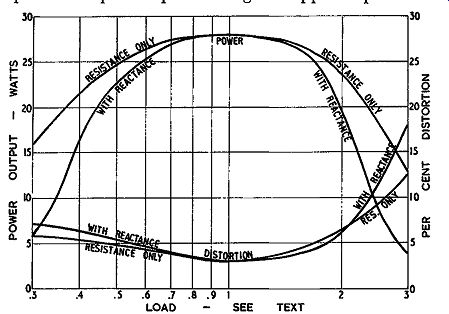
Fig. 211. Output characteristics for ultra-linear operation as loading
is varied.
Effective plate resistance
Closely associated with the matter of grid drive is the effective ac resistance the stage presents to the output terminals. Matters such as damping factor and feedback are discussed in the next section. We will see when we come to that point, that there is a limit to what can be done. This means we should also compare the starting point provided by the methods of operation so far discussed.
The straight triode operation of the 5881, with a 4,000-ohm plate-to-plate load resistance and 45 volts fixed bias, gives an average ac resistance in the plate circuit of 5,600 ohms or about 1.4 times the load resistance. This means that, on the secondary of the output transformer, a 10-ohm speaker would be feeding from an effective source resistance of 14 ohms, due to the plate resistance of the tubes.
Some readers may wonder why the triode resistance is as high as 1.4 times the load resistance. The usual value given is in the region of 0.3. This is based on the older method of operating triodes, in class-A, when the ac resistance is usually a fraction of the load resistance. For example, in the automatic circuit, using the values given for Fig. 205, the source resistance is about 3,200 ohms plate-to-plate, which is 0.4 of the load resistance. This means that a 10-ohm loudspeaker matched to this circuit would be fed from a source resistance of 4 ohms.
In pentode operation the effective ac resistance is between 5 and 10 times the load resistance but it is not constant throughout the output cycle. This is an additional reason why feedback is necessary for pentode stages: to linearize the ac resistance of the output stage.
The ultra-linear circuit, working with a plate-to-plate load of 6,500 ohms gives an ac source resistance of about 1.25 times the load resistance. This means a transformer matching a 10-ohm loudspeaker would provide a source resistance of 12.5 ohms, in the absence of feedback to modify this.
From this comparison the ultra-linear again shows up as the best starting point because it has the lowest ac resistance compared with the load resistance (except for the triode automatic bias circuit which gives only 8 watts output).
Cathode followers
The simplest variant from straight triode, pentode or ultra linear operation is to use the tube as a cathode follower. This means that the plate is effectively grounded in place of the cathode and the output power is taken from the cathode circuit instead of the plate. Actually, of course, the tube still needs B plus to operate it so this means the plate is returned solidly to B plus instead of through the output transformer.
Fig. 212 shows the cathode-follower circuit for 5881's operating as triodes. Turning back to the tube characteristics of Fig. 202, the plate swing is from the operating voltage of 400 down to 238 for a 45-volt grid swing in each direction. Under the quiescent condition there is 400 volts from plate to cathode and the grid is 45 volts negative from the cathode. When the grid swings 45 volts positive from this-or to the same potential as the cathode the cathode swings 162 volts positive from its normal potential, which means the grid drive must swing a total of 162 + 45 = 207 volts positive from its normal potential.
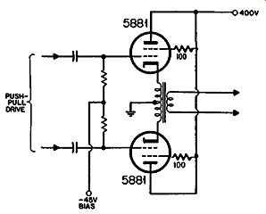
Fig. 212. Circuit for operating push-pull triodes as cathode-follower
output.
So the triode cathode-follower circuit will require a peak-to-peak swing of 414 volts for each tube. The power output will be the same as in straight triode push-pull, but let's see what hap pens to the distortion.
Of the 207 volts excursion applied to the grid, the 162-volt component from cathode to ground will contain 4.4% distortion of the 45-volt component from grid to cathode. But the total voltage of 207 is undistorted because it is the input voltage applied.
So this means that the 45- and 162-volt components will each contain a distortion element in opposite phase.
If the 45-volt component possessed 4.4% harmonic, the 162 volt component would be pure, and vice versa. So the harmonic components will be about 3.4% of the 45 volts and 1 % of the 162 volts, each of which amounts to 1.6 volts. But the 162 volts is the power output voltage. So this means that this method of operation has reduced the distortion from the region of 4.4% to about 1%· The source resistance provided by the cathode-follower triode operation is 1,250 ohms, referred to the cathode-to-cathode winding, for which the load was 4,000 ohms. This is a source resistance of 0.31 times the load resistance.
Pentodes may be operated in a cathode-follower arrangement by using the circuit of Fig. 213. This requires a transformer with an extra winding because the screen has to swing with potential variations identical to the cathode. In this case the input swing required is 280 volts for the cathode-to-ground output plus 22.5 volts for grid to cathode, a total of 302.5 volts.
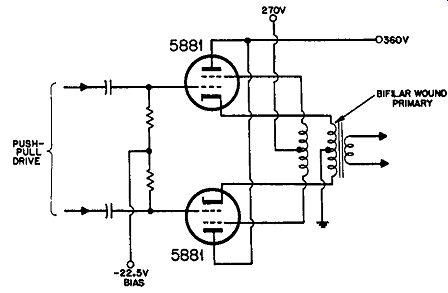
Fig. 213. Circuit for operating as pentode cathode-follower output.
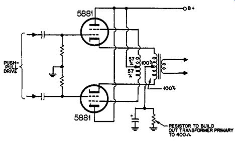
Fig. 214. Circuit for operating as ultra-linear cathode follower output.
Using the same reasoning as for the triode, this will reduce the distortion figure from 2% to about 0.15%. Under this condition there will be an effective source resistance of 450 ohms cathode-to cathode which is .068 times the nominal cathode-to-cathode load of 6,600 ohms. Thus there is some advantage to the pentode cathode follower compared with the triode cathode follower: first with regard to d1stort1on and second in reduction in source resistance. But this is at the expense of a greater swing-302.5 volts per grid as against 207. And remember, the pentode connection uses a plate voltage of only 360 compared to 400 for the triode.
It would also be possible to operate the ultra-linear circuit as a cathode follower by coupling the screen so that its voltage swings by 57% of the cathode swing while the plate voltage is connected to B plus, as shown in Fig. 214. This would increase the required grid drive to 345 volts peak or 690 volts peak-to-peak, which is even more drive than that required for pentode operation. The distortion will be reduced to less than 0.5% and the source resistance will appear to be about 1, 100 ohms cathode-to cathode or about one-sixth of the load resistance.
Full cathode-follower operation in either of the three major circuits is not generally used in practice because it is as difficult to obtain (without distortion) the very large drive voltages required as to design the output stage itself with low distortion.
However there are a number of circuits which are virtually "half way" toward the cathode follower so consideration of cathode coupling provides a good basis for understanding the other combinations.
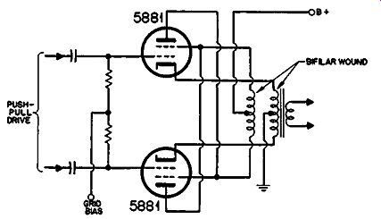
Fig. 215. The unity-coupled circuit.
Unity coupling
The first of these is unity coupling. The circuit for this is shown in Fig. 215. It is virtually a pentode circuit which is a halfway cathode follower. This means that the plates, screens and cathodes all swing by equal amounts but the phasing is such that each screen swings in exactly the same way as the corresponding cathode while the plate swings in the opposite direction.
For both the pentode cathode follower and this circuit, the de sign of the output transformer is extremely important. It is vital that the screen shall be tightly coupled to its corresponding cathode, otherwise instability will occur. For this reason the screen or plate winding is wound bifilar with the cathode winding. This means that the turns are put on side by side at the same time. As the full B plus voltage thus exists between adjacent turns, this method of winding requires extremely good insulation on the wire covering.
In this case the grid swing needed will be half the total output swing, or 140 volts, plus the 22.5 volts grid swing, a total of 162.5 volts, or 325 volts peak-to-peak for each tube. This is rather less than is required for the cathode-follower triode arrangement.
Note that the plate and screen must get the same supply voltage in this case because they use the same winding. This will modify the figures given slightly because these were taken for a screen voltage of 270 with a plate voltage of 360. Distortion will be a little less than 0.3% and the source resistance about 0.13 times the load resistance.
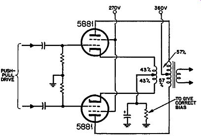
Fig. 216. A modified ultra-linear circuit used by several amplifiers.
Modified ultra-linear
Another variant that can be considered as a partial cathode follower arrangement connects the B plus directly to the screen in what is virtually an ultra-linear circuit. This is shown in Fig. 216. Here to apply the ultra-linear condition strictly, the swing on the plate and cathode will be unequal so that the cathode-to screen and screen-to-plate swing voltages are in the ratio of 43 to 57. In practice, different proportions may also be used.
This circuit conveniently enables the screens to be operated at a lower B-plus point where the tubes are better suited for operation that way. Assuming the same 400-volt supply for both, we can deduce the relative performance from the ultra-linear data already given.
The power output will be 28 watts, as before. The distortion reduces to about 0.85%, almost pure third harmonic and the source resistance to about 0.32 times the load resistance. The grid drive for this arrangement will be 45 volts grid-to-cathode, plus 43% of the original ultra-linear plate swing, 300 volts, from cathode to ground. This is 174 volts peak, or 348 volts peak-to peak. This circuit will be recognized as forming the basis of quite a number of commercial amplifiers.
Circlotron
The last circuit we shall consider in this section is known as the Circlotron, shown in skeleton form in Fig. 2 1 7. This requires two separate B-plus supplies, which are shown for convenience as batteries in Fig. 217 .
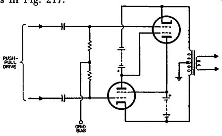
Fig. 217. Basic Circlotron circuit. The drive arrangement is omitted
for clarity in tracing the behavior of the output circuit itself.
Why would a designer go to the trouble of setting up two completely separate B-plus supplies for an output circuit? The principal reason is that this arrangement avoids one of the problems present with all the other circuits: very special attention to the design of the output transformer. This circuit avoids the need for critical coupling between sections of the primary of the output transformer, a feature in the design of all the other special circuits. Hence a much lower cost output transformer can be used with this arrangement. This may well offset the extra cost of pro viding separate high-voltage secondaries on the power transformer.
These tubes are acting as pentodes because the cathode and screen are separated in each case by a constant potential. The tubes are virtually parallel, each cathode being connected to the other plate through a B-plus supply, with the output transformer being connected across the whole combination. This is where this circuit differs from the normal push-pull arrangement in which the two tubes virtually feed the load in series, not in parallel. The result is that the plate-to-plate load-or cathode-to-cathode load, whichever you prefer to call it-has a value one-quarter that used in the case of the normal push-pull pentode output.
Table 1. COMPARATIVE QUALITIES OF OUTPUT CIRCUITS (Based on 5881 tube)
* Plate efficiency = audio output/ plate dissipation.
As this is a pentode circuit, using the same operating conditions, the primary loading impedance would be 1650 ohms.
The two B-plus supplies are both "floating," one at each end of the output transformer winding. Ground is provided by the center tap of the output transformer. If the output tube grid drive was returned to ground, the arrangement would be somewhat similar to a cathode-follower circuit because the swing at the grid would have to provide the grid swing in addition to the output swing on the cathodes or plates.
This is partially offset in the Circlotron circuit by returning the B-plus for each tube of the push-pull drive stage to the positive voltage from the opposite output tube. See Fig. 426, section 4.
Using ground as a reference, the plate and cathode will each swing a peak of 140 volts, as considered in the unity-coupled arrangement. The grid will need to follow the cathode swing, with an additional 22.5 volts making a total of 162.5 volts-still the same as the unity-coupled arrangement. This is a peak-to-peak of 330 volts but, with the cross-connection used in the plate supply, the top end of the plate coupling resistor swings 280 volts while its bottom end swings 330 volts.
This means the dynamic load line for the drive tube is multi plied by a factor of 7.2. For this reason a fairly low-value coupling resistor can be used to keep the plate voltage up but the dynamic line will be over 7 times this value. This feature enables a comparatively small drive stage tube to be used.
The power output from this stage will be the same as from push-pull pentodes with the same operating voltages. The distortion will be reduced by a factor similar to the unity-coupled arrangement and the source resistance will also be similar to it. To verify this, note that, although the tubes are connected in parallel (which reduces their resultant resistance) this reduces the step down available in the output transformer to produce correct matching because the tubes also share the load in parallel, the center tap being provided in this circuit only to obtain a ground reference for the rest of the amplifier. So we end up with the same relationship as before.
The principal difference between unity coupling and the Circlotron circuit comes in the matter of component design. The unity-coupled arrangement requires a bifilar-wound output trans former and no particular attention to the power supply design.
The Circlotron circuit can use a much less expensive output transformer but requires a special power supply with two separate floating B-plus supplies.
Table 1 summarizes the properties of the various circuits discussed in this section.