THE basic requirements of this section of the amplifier are (1) to provide a balanced drive signal for the grids of the output tubes from a single-ended input and (2) to provide enough swing of this balanced output to drive the output tubes to full power.
Of course, there should be a slight margin here, at least to insure that the output tubes are the limiting factor for the maximum power delivered by the amplifier and not some earlier stage.
Factors considered
Each circuit will be fully considered in relation to the available grid swing that it will give for a specified B-plus voltage. It is recognized that the swing any tube gives is a function, not only of the tube characteristics, but of the B-plus voltage available for its plate circuit.
Next in importance is the degree of balance that can be achieved by the circuit and also how much the balance of the drive provided for the output tubes depends upon the individual tube parameters. Circuits which give a high degree of balance regard less of deviations in individual tube parameters, are obviously better than those which require careful matching or control of tube characteristics.
Not only must the balance be arranged to give accurate anti phase voltage to the grids of the two output tubes, it must also preserve this relationship accurately throughout the frequency range handled by the amplifier. This means that the phase in version must be accurate at all frequencies.
Another important feature is the amount of distortion it con tributes to overall performance. Earlier stages in an amplifier usually operate at relatively low levels where (if the distortion is still on the large side) it is a simple matter to provide overall voltage feedback to reduce the distortion to acceptable limits.
But, like the output stage, the phase inverter and driver stages handle relatively large signals. The output stage delivers relatively large power and the phase inverter and driver stages work with relatively large voltages. So the distortion-not only as to quantity, but as to kind-is important.
A final feature is how the phase inverter and driver stages affect the use of feedback. This can be considered from two viewpoints:
1. The design of the phase inverter and/or driver stage may need to include arrangements. for short-loop feedback from the output stage to provide a satisfactory starting point for raising the damping factor to a successful figure. For this the design must have convenient points to which to make the local-loop feedback connection.
2. Different circuits will contribute different frequency response parameters that will affect the overall stability criteria of the complete loop for low- and high-frequency response determination.
Direct-coupled transformers
The first and obvious type of phase inverter to be used was the simple transformer, connected directly in series with the plate in the preceding stage (Fig. 401). This component has had little use since the early days of amplifiers, largely because it was dismissed as a prominent cause of distortion. This was due to two principal factors: (a) inadequacy of core materials at that time for audio applications (modern core materials have made possible consider ably improved audio transformers) and (b) the fact that most of the available transformers were nowhere near as good as they could have been made with a little more care in design.
At one time, when audio amplifiers were part of a radio receiver, quality was not so important as gain. The average audio section consisted of a number of low-magnification battery-operated triodes, coupled by high step-up interstage transformers. These had any number of turns wound on some convenient bobbin plus laminations of nondescript steel. The whole was then placed in a container to hide the shabby construction and this was sold as an audio transformer.
Both the frequency response and the distortion of these units were very poor. Long before the feedback amplifier these components had fallen into disuse, except for limited applications, be cause of prejudice against them arising from their poor workmanship.
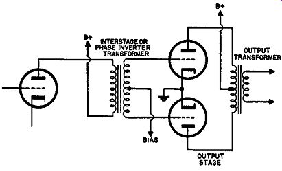
Fig. 401. Simple circuit for transformer phase in version.
Yet, a well-designed interstage transformer, including one of the phase-splitting variety, can yield quite good performance. In fact when correctly designed, it has many advantages over some of the later types of phase splitters. Due to the relatively low primary resistance, the plate voltage need not be much lower than the B-plus voltage. This enables the tube to deliver a large swing on the primary side of the transformer.
In addition, the use of a low-mu triode such as half of a 12AU7 permits a considerable step-up ratio to be achieved between primary and each half-secondary. Thus this circuit will certainly beat any other for providing the maximum voltage output handling capacity for a given B-plus voltage.
It also scores on the stability of balance against tube parameters, for the reason that the balance is dependent only upon the trans former's being accurately wound in the first place. If the tube gain drops, then the output on both sides of the secondary will drop in the same proportion.
It is possible to achieve a high degree of balance in the trans former frequency response. At the low-frequency end the inductance produced by the core, reflecting to the primary winding, produces a low-frequency loss and phase shift. The step-up ratio of the transformer produces a replica of this frequency response both in amplitude and phase shift for each grid so that, whatever the frequency characteristic produced on the primary, an identical one, at larger voltage because of the stepup, will appear on both halves of the secondary.
At the high-frequency end more care in the design of the trans- former is necessary to maintain balance. Nevertheless a well-de signed unit can provide identical winding capacitances and leakage inductances for each half, thereby maintaining uniform phase relations between the drive for the two outputs.
Careful attention to the associated operating impedances can also achieve a much better frequency response than is usually believed.
Due to the unhappy experiences of early days, interstage trans formers are widely accused of producing distortion. However, a well-designed component will result in a given voltage swing at the output with much less distortion than any of the newer tube circuits. This may come as a surprise to some readers but it has been verified both in design and practical comparison. Of course a high-quality interstage transformer is more costly than the extra tube which might be needed to replace it, with a few extra resistors to help out, but performance-wise the transformer wins except on one point.
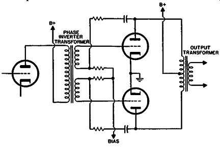
Fig. 402. Transformer circuit provides short-loop feedback without absorbing
appreciable power from the output circuit.
This is its relation to feedback circuits. From one standpoint the interstage transformer even has an advantage here (Fig. 402). It enables a local-loop feedback to be arranged over just the output stage by itself-an arrangement which proves to be ideal because it is inherently stable and cannot produce peaking. Because the feedback resistors are virtually in the grid circuit of the output tubes, this arrangement enables values to be used which do not absorb appreciable power from the output-a factor which discriminates against the use of extensive local-loop feedback when this is connected into the cathode of the driver stage.
There is a limit to the amount of negative feedback that can be applied in this manner because there is also a limit to the swing that can be obtained from the preceding stage and to the amount of stepup that the transformer can provide with a reasonable frequency response. It will be realized here that the frequency response of the transformer does not come inside the local-loop feedback.
The real disadvantage in the use of any type of interstage trans former comes at the high-frequency end when considering overall feedback. At the low-frequency end the transformer does not have any serious advantage or disadvantage compared to resistance capacitance coupling. R-C coupling introduces a single reactance producing low-frequency rolloff and the primary inductance of the transformer does the same thing in a different manner. So, for this purpose, both methods of coupling start level.
But at the high-frequency end the transformer contributes a number of reactances. There is the primary capacitance, the leak age inductance between primary and secondary and the secondary capacitance. This results in a network whose ultimate high-frequency phase shift is 270°. Compared with this, any R-C coupling between stages produces a maximum phase shift of only 90°. Additionally, there is no serious difficulty in designing an R-C-coupled stage whose 3-db point is as high as 100 kHz, or even higher, whereas the reactances combining to effect rolloff in a transformer can be pushed up to around 20 kHz but this is about the limit. This means that a single interstage transformer in an amplifier with, say, three more stages, cannot use more than about 6-db overall feed back before instability occurs. Almost any feedback at all will begin to produce peaking in such an amplifier.
This is the principal reason why it is not practical to use inter stage transformers in modern amplifier design. However the facts have been presented fully so that application of interstage trans formers can be considered where this reason may not be pertinent.
From the designer's viewpoint the direct-coupled transformer has problems, particularly in achieving a wide frequency response.
Since current flows through the primary winding, it is difficult to achieve a high primary inductance. The core has to be gapped to reduce saturation effects. This means there is little advantage in using the high-permeability modern materials. Consequently the direct-coupled transformer is inherently limited to a somewhat restricted frequency range.
Parallel-fed transformer
This situation is considerably improved by the use of parallel coupling (Fig. 403). This avoids passing the plate current through the primary of the transformer and makes for a much larger primary inductance with fewer turns on a smaller transformer. With improved core materials, a parallel-fed transformer can attain much wider frequency range than a direct-coupled transformer However, it has certain strikes against it immediately. Because the plate has to be fed through a coupling resistor, the working plate voltage is much lower. This will restrict the swing avail able on the primary to half, or maybe less, than that available for the direct-coupled transformer. So, to produce the same swing on the secondary, the parallel-fed transformer needs to give twice, or more than twice, the stepup designed into the direct-coupled transformer type. Usually this can be done.
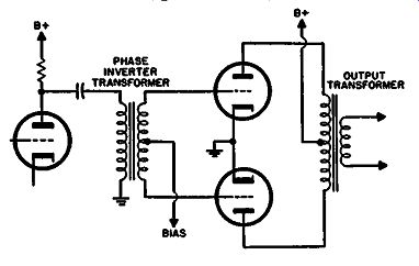
Fig. 403. Parallel-fed transformer improves frequency band possibilities
and makes a bigger step-up available.
But there is yet a further disadvantage. At the low-frequency end we now have two reactances contributing to rolloff instead of the simple inductance of direct feed. The coupling capacitor produces a loss of low frequencies while the primary inductance provides a further shunt loss. These two components have to be correctly matched with the circuit impedances to provide a good low-frequency response without peaking and without undue loss.
At the high-frequency end also, the change in stepup introduces troubles that offset some of the gain achieved by the change in transformer type. With the much smaller physical size and bigger stepup, the primary capacitance effects are negligible compared to the direct-coupled type. Although the winding capacitances on the secondary side are very much less than those in the physically larger direct-coupled transformer (the leakage inductance can be considerably smaller on this account) the larger stepup ratio means that the effective source resistance provided by the plate circuit of the preceding tube is about quadrupled. This means that the leakage inductance and secondary capacitance must be divided by 4 if their effect on high-frequency response is to be of the same order as in the direct-coupled case.
Most of the advantages gained by parallel-feeding the transformer are in effect lost due to its disadvantages.
Tapped AF choke
Another variation that uses inductance is the tapped AF choke circuit (Fig. 404). This provides phase inversion without the stepup that the parallel-fed transformer will give. One of the output grids is directly coupled (via a capacitor) to the voltage amplifier plate while the other is inductively coupled.
Its stability of balance with tube parameter variation is as in dependent as any transformer. Its distortion is about the same as any voltage amplifier stage, giving the same swing each side as the voltage amplifier delivers. By not too complicated design the response can be made very good although the balance will always go off at some high frequency because of the leakage inductance between halves, which only affects the "lower" output grid. Also, it is not readily suitable for local-loop feedback because there is no isolation between primary and secondary, as with a full trans former.
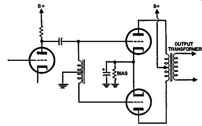
Fig. 404. Circuit using a center-tapped audio choke.
Split-load inverter
The first type of tube phase inverter to be introduced is called by various names. The most descriptive would seem to be "split load." However other names, such as concertina, fifty-fifty, cathodyne and the like, have also been used. The basic circuit is shown in Fig. 405. Half of the plate load is connected between the plate and B-plus while the other half is connected between cathode and ground. Since, at any instant, the same plate current flows through both these resistors, the voltages must both change accordingly. If the resistors are made identical, then both halves will be identical.
Obviously, however, the swing that can be derived from this stage will only be half, at the plate or cathode, of the swing that could be achieved using the tube with the same total resistance, all in the plate. In addition, the previous stage has to deliver a driving voltage slightly larger than the output swing obtained.
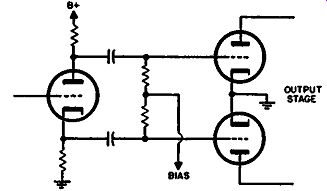
Fig. 405. Basic circuit of split-load inverter.
As an example, a 12AU7, using typical values, will give a gain of about 10 into the total plate load chosen. This means 5 at the plate and 5 at the cathode; so I-volt swing between grid and cathode will give 5 volts between cathode and ground and 5 between plate and ground. But the input swing needs to be the combined voltage of grid to cathode and cathode to ground-a total of 6.
So, with the 12AU7 as an example, the input voltage has to be 1.2 times the output voltage to each grid.
The most serious limitation of the split-load phase inverter is that its output is restricted because the load is split. It may even be necessary to employ a further stage of amplification between this phase splitter and the output tubes themselves. Additionally, a large input is needed; the tube does not provide any gain--instead it gives a slight loss.
As regards balance in frequency response, the circuit is excellent. This is contrary to what many authorities write so perhaps it will be well to investigate here just what this tube does.
The reason given for describing the tube as giving poor balance is that the source resistances at the plate and cathode are very different. From the viewpoint of the plate, the tube is operating with a large degree of current feedback due to the resistor in its cathode while, from the viewpoint of the cathode, the tube is operating halfway to being a cathode follower. So the resistance "seen" at the plate is several times the ac resistance of the tube, in parallel with the actual coupling resistor used, while the resistance "seen" at the cathode is much lower than this. Any reactance inserted in the plate circuit will have a different effect from the same reactance inserted at the cathode circuit.
One point has been overlooked however. We do not normally insert reactances in one of the output circuits that we do not put in the other. If one tube uses a 0.1-µf capacitor for coupling, the other one will invariably use the same value. Also the grid-to ground resistors (or grid-to-bias-point resistors) for the output tubes will invariably be identical too. Stray capacitance between the output tube grid and ground will usually be similar.
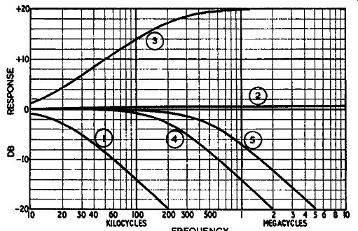
Fig. 406. Responses showing the effect of shunt capacitance from plate
and cathode of Fig. 405: Curves 1 and 2 show response at plate and cathode
respectively when capacitance is connected in plate only. Curves J and
4 show response at plate and cathode only. Curve 5 shows response when
equal capacitance is connected at both plate and cathode, both places
giving the same response.
If any of these components acted only in one circuit and not in the other then an unequal effect on frequency response would occur. But, because both happen simultaneously, balance is main tained. Because the plate and cathode circuit of the split-load inverter each contain an identical network of impedances at all frequencies the voltage across the two halves of the load is equally divided.
Consider the effect of capacitance across each section separately, not only on the output at that point, but on the other half too.
A capacitance at the plate causes a rolloff at the plate and a very slight boost at the cathode, due to the change in effective gain as a partial cathode follower. A capacitance at the cathode causes a much more remote rolloff at the cathode but a very considerable boost at the plate, due to the effective removal of cathode circuit degeneration by a bypass capacitor. This is illustrated in Fig. 406.
It is evident that the response at the plate is subject to much greater fluctuation than that at the cathode. But if the impedances in both circuits are equal, the response at both points will be flat.
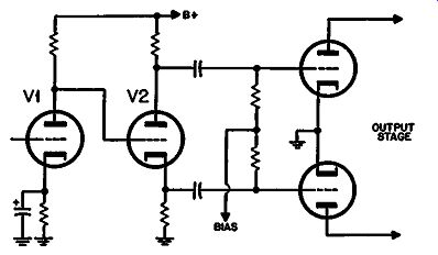
Fig. 407. Split-load inverter with a direct-coupled preceding stage.
This statement does not apply to distortion that occurs due to grid current flowing in the following stage. Obviously the cathode is better equipped to supply grid current than the plate, due to its lower effective source impedance. In this case the tube currents do not flow simultaneously, but at opposite peaks, hence the balancing effect noted with regard to frequency-response parameters does not apply to distortion cancellation.
Distortion in the split-load inverter itself, can be deduced from the distortion produced by this tube with the operating load, divided by the negative feedback factor between grid and cathode.
However, the fact that a large swing is required to drive the split- load inverter may mean that the previous stage needs to be operated under conditions that involve higher distortion than would be necessary with an inverter in which there is some gain.
Where the split-load phase inverter immediately precedes the output tubes, it does not provide convenient points for local-loop feedback from the output tube plates. However, if it is used ahead of a separate push-pull driver stage, then local-loop feedback can be used between the output and driver stages independently of the split-load inverter.
Sometimes the split-load phase inverter is seen directly coupled to the plate of the preceding stage. This is possible because its grid is a few volts negative of the de operating potential of its cathode. For some circuits this is not too low a plate voltage for the preceding stage (Fig. 407). In this circuit, however, the preceding stage must be considered as part of the phase-inverter circuit because the plate voltage of the preceding stage V1 directly controls the grid voltage of the phase inverter V2 and this must not only get the correct voltage swing to drive the output tube but must have the correct bias so that this swing is available without undue distortion. For this reason it is usual to control the voltage of the preceding stage by using a rather larger cathode bias resistor than usual with a correspondingly large value of plate resistor. This tends to swamp fluctuations in the tube parameters and make the tube a constant current device from the de viewpoint. The tube gain, if necessary, can be restored by bypassing the rather large cathode resistor by a suitable bypass capacitor.
Para phase
The next variety of phase inverter to receive consideration is that called paraphase. This uses an additional stage to provide phase reversal. Most of the remaining types are really variations of the original paraphase. In its simplest form the method consists of using one stage to amplify the signal for the grid of one output tube and then attenuating into a further stage that provides the signal for the opposite output grid. By arranging that the attenuation between the stages is equal to the gain of the second tube, both grids will receive equal voltages but in opposite phase due to the reversal effect in the tube (Fig. 408).
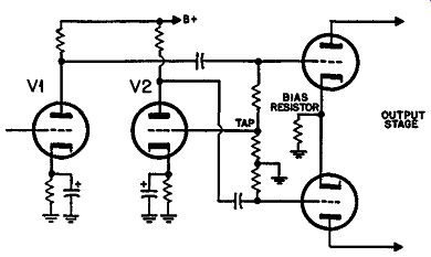
Fig. 408. Simple "paraphase" circuit.
The simple paraphase circuit has an advantage over the split load in that each output tube grid receives the swing from a whole plate load. This means that, using the same tube type, the avail able swing is about twice that of the split-load phase inverter for a given amount of distortion.
In addition, the second tube will provide some distortion cancellation. The first tube, of course, will provide its quota of second-harmonic distortion in the drive to the first output grid, due to the curvature of the tube characteristic. Assuming that the two tubes used in the paraphase circuit are identical, this curvature will be attenuated and then amplified by a tube in opposite phase. The identical tubes will produce equal components of second harmonic but in opposite phase. The second harmonic should cancel in the second paraphase tube so that the second output tube receives zero second harmonic in its drive. Ignoring for the moment the distortion effects of the output tubes themselves, when the signal is recombined in the plate circuit the resultant distortion will be approximately half that in the drive to the first tube grid (Fig. 409).
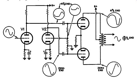
Fig. 409. Effect of a paraphase circuit on the distortion produced in
the tubes.
The big disadvantage of the simple paraphase circuit is that the balance is entirely dependent upon the tube parameters. If the gain of the second tube changes from the value used in deter mining the attenuation, then the drive for the output tubes will not be the same.
A further disadvantage occurs in the balance with regard to frequency response. Since there is an extra stage of coupling for the second output tube, this means that it must suffer additional phase advance and loss at the low frequencies and also additional phase delay and loss at the high frequencies. The drive for the two output tube grids is not identical over the whole frequency range nor in exactly opposite phase even though it may be so at a mid-band frequency where these reactances have no effect.
This simple paraphase circuit is of course quite inconvenient for the application of feedback because a local-loop feedback can-not conveniently be injected into either tube without upsetting the balance for the other.
As regards the stability criteria of the complete loop, the extra reactance for the second output tube both at the low and high ends means the circuit constitutes an additional liability in overall feedback design.
Output-coupled paraphase
An interesting variant of the simple paraphase circuit is one in which the output stage is virtually its own phase inverter (Fig. 410). Here the drive for the second output stage (V2) grid is obtained from a tap in the plate circuit of the other output tube (V1). This can be obtained, either from a suitable tap on the primary winding of the output transformer or by a resistance potentiometer across that half of the winding.
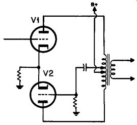
Fig. 410. Simple output-coupled paraphase inverter.
There is no particular advantage, performance-wise, to either method. The tap on the transformer saves the necessity for two additional resistors which may need hand-picking for close tolerance values.
Most of the disadvantages inherent in the paraphase circuit apply to this one. From the viewpoint of overall design it might be considered as a single-ended output stage because the push-pull action is derived within the stage itself. Because of this, the additional stage necessary with the normal paraphase arrangement is avoided, hence the additional parameters involved are to some extent not needed. In other words there may be one less stage in the overall loop.
On the other hand the stability of balance against tube parameters is seriously aggravated here because the gain of each tube is dependent upon its receiving the correct plate load, especially where the tubes are pentodes. Practical speaker loads do not provide the ideal load resistance for the tubes. If this load value is higher than nominal, this means that the drive provided for the second tube grid will be larger than that for the first. The second tube will provide a greater proportion of the total output power available than the first tube. The second tube will accordingly run into distortion before the first one and the output will be cut down considerably from the nominal push-pull normally avail able from the two tubes used. Of course, lightly loading any pair of tubes reduces the available output due to the fact that the optimum load is not used. But the effect just discussed is over and above the loss of power caused by normal mismatching and is due to the fact that the tubes are operating with unequal input swing and with unequal effective plate loading (Fig. 411).
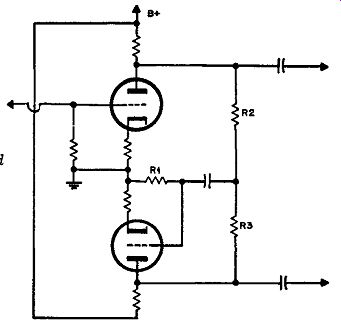
Fig. 411. How loading affects the individual tubes differently with
the circuit of Fig. 410.
Another disadvantage of this circuit is that the waveform fed to the second tube is the output from the first tube. Closely coupled with this is the output from itself, phase-reversed by the transformer. This will minimize distortion from the second tube but cannot do so from the first. Due to "load-switching"--during different portions of the cycle each tube supplies different portions of the total power ( even when correctly matched)-the first tube will introduce more than the usual amount of distortion anyway.
When these two effects combine, as they naturally do when the load value deviates from its theoretical value, this stage produces quite a comparatively high quota of distortion, even at relatively low levels.
Floating paraphase
Two more types of phase inverter can be regarded as modifications of the paraphase type. The first is called the floating paraphase, of which one variant is shown in Fig. 412.
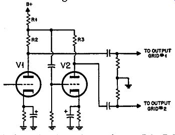
Fig. 412. Variation of the floating-paraphase inverter circuit.
Its design hinges on the choice of values for resistors R1, R2 and R3. The drive for the grid of V2, is taken from the junction of these three resistors. If R2 and R3 are equal and the signal voltages at the plates, for delivery to the output tube grids, are assumed equal and opposite in phase, then the current swing through R2 and R3 must also be equal and opposite in phase.
This means R1 has no current swing so the junction of the three resistors cannot swing at all. For this reason the grid of the second tube receives no drive. Hence the assumption that the output voltage of the second tube is equal to that of the first tube V1, is impossible.
The current swing of the first tube must be slightly larger than that of the second, so the voltage produced by the difference in current swing in R1 will give the correct grid drive voltage for the second tube.
To illustrate the advantage of this method of operation, let's put in some figures. Suppose that the current swing of the first tube is 10% greater than that of the second one-that is, the relative swings are in the ratio of 11 to 10. The current swing in resistor R1 will be 1/10th of the swing in the second tube or 1/11 th of that in the first tube. By making the resistors in opposite relationship-that is, R3 is 10% greater than R2, the signal swing at the plates of the tubes will be identical again.
Now assume that the transconductance of the second tube drops by 10%. This would mean that, instead of producing 10/1 lths of the current swing provided by the first tube, it would produce only 9/llths and therefore the grid swing existing at the junction of the three resistors would be twice the value it was be fore. This is impossible because then, even with the 10% reduced transconductance, the output would be 1.8 times its previous value from this tube--or a greater current swing than the first tube.
Of course the circuit readjusts itself by the "floating" effect so that the available grid swing rises by 10% to offset the drop in transconductance. This means that the current swing ratio, instead of being 11 to 10, will increase to 10 to 9 and correspondingly, since the resistors are designed for a ratio of 11 to 10, the output at the plates will differ by about 1 % for a 10% drop in the transconductance of the second tube. Thus, the floating paraphase considerably reduces the dependence of the circuit upon the operating parameters of the tubes.
Now we come to the disadvantages. Assuming that the tubes provide a working gain of 20 each, the current passing through R1 is only 1/10th of the current swing in the second tube or 1/11th of that in the first tube. To produce 1/20th of each plate voltage will mean that R1 must be half the value of R3. Since the R1 carries the combined plate currents of both tubes, there will be as much voltage drop across R1 as across R2 or R3.
This circuit results in a serious lowering of the effective B-plus available for the tubes. It is not quite as bad as the split-load arrangement, because the junction does not receive half of the output signal voltage-only about I/10th. So R2 and R3 do receive almost the entire output of the tubes, but only at the operating B+ voltage present at the junction of the three resistors. This way each output is slightly more than that obtained from the split-load arrangement, but not very much.
The exact relationship will depend on the tube type used for comparison. Take the 12AU7 with a supply of 300 volts: for the split load inverter, a load of 50,000 ohms and a bias of -10 volts gives an operating point of 180 volts, and a total swing from 50 volts to 260 volts gives 105 volts peak-to-peak at both plate and cathode; the paraphase will supply the full 210 volts at each plate; but the floating paraphase will lose half the operating drop in the common resistor, so we use an effective plate supply of 240 volts with a load resistor of 25,000 ohms; biasing to -7.5 volts, the available output swing per plate is from 60 to 210 volts, or 150 volts peak-to-peak.
There is an advantage over the split-load arrangement in that the tubes have an effective gain. The gain will actually be quite similar to the combined arrangement of two tubes, the second of which is a split-load inverter (Fig. 407). With this circuit the balance in frequency response is a little better than the standard paraphase circuit because there is effectively a degree of negative feedback operating over the second stage. This happens because the voltage applied to its grid is de rived from the current swing of the two tubes combined in R1, hence part of the voltage applied to the grid of this stage is due to the current in its plate circuit. This means that the additional coupling parameters, due to stray capacitance from the junction of R1, R2 and R3. for the high end and the coupling capacitor between this junction and the grid for the low end, have their effective frequency band extended by the apparent amount of negative feedback.
This extends the range of frequency over which the phase inversion maintains effective balance. It also improves the problem of stability criteria over a complete feedback loop compared to the simple paraphase circuit.
As the tubes use separate bias resistors it is feasible to arrange local-loop feedback from the plates of the output tubes to the cathodes of the floating-paraphase tubes.
This circuit produces distortion cancellation inferior to the direct-paraphase arrangement. Not too obvious, it can be deduced as follows: The voltage for the second tube grid is obtained by the difference between two currents that would contain almost equal second-harmonic percentages, assuming that the voltages at their grids are the same waveforms but antiphase. Although the fundamentals almost cancel in R1, the second-harmonic components would be additive. But feedback via the second tube grid tends to cancel this combined second-harmonic component of current. It cannot reduce the actual second-harmonic component of current swing in the first tube but will set up antiphase current in the second tube to neutralize it. Thus the signal for the output tube grids will contain approximately equal proportions of second harmonic but in opposite phase-the same as the fundamental.
This will not cancel in the output.
Another way to view this is that the second tube of the floating paraphase acts as a feedback current inverter for the plate current of the first tube, which has no feedback. Thus the harmonic generated by the first tube gets inverted along with the fundamental.
Another variation of the floating paraphase puts the critical resistors in the grid circuit of the output stage instead of the plate circuit of the paraphase couple (Fig. 413).
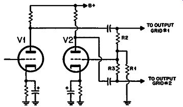
Fig. 413. Another variation of the
floating-paraphase circuit.
However this circuit does provide a larger swing because the full supply voltage is retained; here R1 has a difference signal in the grid circuit, which carries no de. There is in practice a very slight loss compared with the straight paraphase because the output tube grids must have not more than a maximum grid circuit resistance. As R1 is common to both circuits, this means that R1, R2 and R3 must be about one-third of the permissible value. For the straight paraphase the full value can be used in each grid. This will shunt the gain of the phase splitter slightly, depending on the tube type and the value of maximum resistance for the output tubes used.
It is possible to eliminate the capacitor between the junction point and the grid of the second tube if ground is the bias return point for the grids of both the second tube and the output tubes.
This does not mean that a low-frequency phase shift has been removed. There is still a phase advance in each of the coupling capacitors from the plates to the resistor triad. This means that the feed to the second output tube grid has virtually passed through one more capacitor in the chain than that to the first output tube grid. However, the presence of negative feedback has effectively increased the value of the additional capacitor.
This means that the difference in phase at the low-frequency end is reduced by the effective amount of feedback provided by floating paraphase action.
Another variation of the floating-paraphase circuit, shown in Fig. 414, is sometimes called the "seesaw" circuit. This overcomes one deficiency of the previous circuit. If the output tubes run into grid current, they will temporarily make the junction point of R1, R2 and R3 (Fig. 413) negative, due to the change of charge on the coupling capacitors. This may change the operating condition of the second phase-splitter tube and can even run it momentarily to cutoff in a serious case. Whether this effect is as serious as the change of bias on the output tubes which accompanies it and whether it causes crossover distortion due to over-biasing depends on individual circuit parameters. The change of circuit in Fig. 414 does not guarantee freedom from effects of this general nature.
Fig. 414. See-saw circuit is modified floating paraphase.
Long-tailed inverter
Another variant that achieves a similar objective to the floating paraphase is given the name long-tailed inverter, the circuit of which is shown in Fig. 415. Here the resistor, in which the currents of the two tubes are combined to provide a difference signal for driving the second grid, is in the cathode circuit of the two tubes. This means that the plate resistors return to B+.
However, there is the same reduction in available plate voltage for the same effective reduction in dependency on tube parameters as in the circuit of Fig. 412, because the same voltage drop will occur across R 1 whether it is in the plate or the cathode of the combined tube circuit. So the handling capacity is precisely similar whichever arrangement is used.
Where a big swing is needed, the output tubes usually use fixed bias, which means that a negative supply is available. By careful design, this can be used for the long-tail return so that the grids of the phase inverter can operate around ground potential. This saves the loss of B-plus and allows the full paraphase swing to be obtained. The circuit is shown in Fig. 416.
Stability of balance against tube parameters is similar because the derivation of the drive for the second tube grid is still the difference between the currents through the individual tubes. The choice of values is made on the same basis.
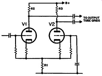
Fig. 415. "Long-tailed" inverter.
In this case, however, the grid of the second tube is at ac ground while its cathode fluctuates; in the floating paraphase, the cathode is at ac ground potential while the grid receives the drive voltage.
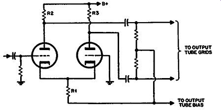
Fig. 416. Alternative of the long-tailed inverter.
An advantage of this arrangement is that the capacitor from the second grid to ground can be made much larger than is normal practice for coupling capacitors. Being at ground potential, it will not introduce additional stray capacitance, thereby affecting the high end. In the circuit of Fig. 416 the second grid is actually connected to ground. This means that its defect in producing an additional low-frequency phase shift can be practically eradicated.
The high-frequency phase-shift situation is also considerably improved in the long-tailed inverter because the impedance at the cathode junction of the two tubes is extremely low. Any stray capacitance at this drive point can virtually be ignored as the impedance is probably less than 1,000 ohms.
The distortion of the long-tailed inverter is much improved over the floating paraphase. Not only does this arrangement give about 6-db overall feedback, but second-harmonic components are fed back to both grids. The long-tailed inverter virtually provides an automatic division of the input grid voltage into two, the floating point at the cathode being halfway signal-wise between the second tube grid, which is virtually at ground, and the input voltage. Since this reduces comparative gain to half, it is equivalent to 6-db overall feedback.
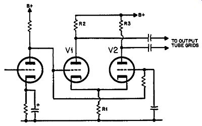
Fig. 417. Variation of long-tailed inverter improves the stability of
the amplifier and saves some components.
This circuit does not provide any convenient point for applying local feedback from the output stage because the cathode circuit is common to the two tubes.
The stability criteria are somewhat improved for the reasons already mentioned, in respect to the improved balance in frequency response. A further advantage in regard to overall stability criteria of a complete amplifier is obtained by direct coupling from the stage before the long-tailed inverter. This can be achieved with the circuit of Fig. 415 because the grid potential of the long-tailed inverter is above ground owing to the necessity for the "long-tail" resistance. This means that, by a design procedure similar to that used for the twin-stage split-load arrangement, a further coupling capacitor can be eliminated. Also, the bias for the second half of the long-tailed inverter can easily be obtained by using a large-value resistor between the two grids and applying just the capacitor to ground. This considerably simplifies the circuit (Fig. 417).
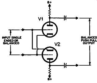
Fig. 418. Basic circuit of the cross-coupled inverter.
Cross-coupled inverter
The inversion part of this circuit consists of two tubes to which the signal is fed in opposite phase (Fig. 418). This circuit was originally designed to accept either single-ended or balanced in puts or ones that were neither. It will mix the input at each grid, giving equal out-of-phase components of each at the plates. To see the effect on a signal at one grid, consider the other one to be held at ground potential (i.e., as a single-ended input). Regarding the lower input terminal to be at ground potential, the upper tube acts "grounded cathode," with the signal applied to its grid, while the lower tube acts "grounded grid," with the signal applied to the cathode.
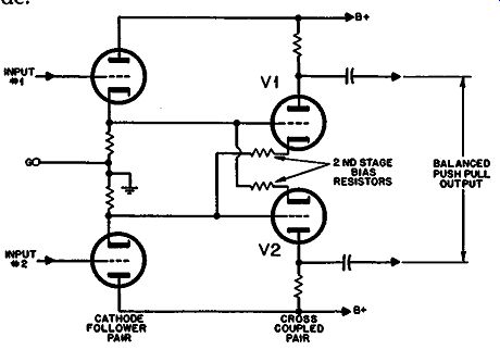
Fig. 419. Practical circuit for cross-coupled inverter includes cathode-follower
pair to drive it.
Because the load impedance of a cathode, in a grounded-grid circuit, is quite low and that of a grid quite high, this circuit must be fed from a source of low resistance to prevent undue loading and possible distortion. For this reason the cross-coupled inverter is inseparably connected with a push-pull cathode-follower arrangement (Fig. 419).
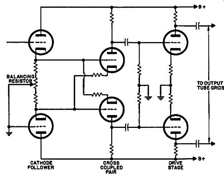
Fig. 420. This type of inverter works better at the front end, with
a driver stage following.
Basically, this was not developed as an audio circuit but as a suitable input for a vtvm or scope. It can conveniently be used as a balanced or single-ended input-or even for an input which is neither-and always gives a true push-pull deflection signal at the output. It obviates the necessity for changing the amplifier connection in some way to change over from single-ended to push pull types of input and is a great asset for this application.
It has been applied, by connecting one of the input grids to ground, as an input circuit for audio power amplifiers. It is possibly somewhat uneconomic for the reason that a single-ended audio amplifier does not require this adaptable feature. The input is either balanced or single-ended-usually the latter, and is not likely to change from one to the other at will. The circuit could be used later in the amplifier to provide a direct drive for the output tube grids except that the cathode follower needs to operate at fairly low level, so a subsequent stage of push-pull amplification is usually necessary between the phase inverter and output as shown in Fig. 420.
It is worth a closer look at the balancing method of Fig. 420. The cross-coupled pair phase-splits the signal delivered at either (or both) the first stage cathodes. This means that adjustment of the control can change the balance only by changing the relative gain in the upper and lower channels. It does this by changing the de component or operating voltages of the cross-coupled pair.
The circuit of Fig. 421 overcomes this objection by using an improved cathode-follower stage, with closely controlled de equality and making the balancing adjustment in the plate circuit of the phase inverter.
The circuit is inherently stable with normal tube-parameter variations but is susceptible to differences between halves of the 12AX7 or cross-coupled pair. The balancing control takes care of this.
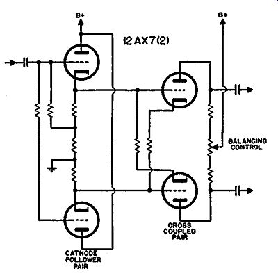
Fig. 421. lmproved cross-coupled inverter.
Balance over the frequency response is particularly good, be cause there are no capacitors in the inverter arrangement to produce low-frequency phase shift. The whole arrangement is direct coupled from the grid of the first input tube to the two phase-inverter plate outputs. From this stage on resistance-capacitance coupling will normally be used and both halves of the push-pull will be identical. This also applies to the parameters affecting high-frequency response.
An advantage of using push-pull amplification over several stages is that, where the grids are at high impedance (those of the second stage of this inverter are not, being connected to the cathode follower), it is possible to use neutralization to overcome the normal high-frequency rolloff parameter (Fig. 422). A capacitance, equal to the plate-to-grid capacitance of the intermediate stage, is connected from the plate to the opposite grid. This means that the normal Miller-effect rolloff is neutralized and the response is extended to an extremely high frequency, such that the parameters of this stage can almost be ignored. This facility is not normally available in audio amplifiers for compensation at the high-frequency-end and is rendered possible only by push-pull amplification.
Push-pull amplification throughout also makes it readily possible to apply local-loop feedback from the output stage plates to suitable cathodes of an intermediate stage.
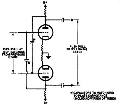
Fig. 422. How high-frequency neutralizing capacitors can be connected
when push-pull triode voltage amplifier stages are used.
Another feature of this cross-coupled input stage inversion is its suitability for overall loop feedback. This can readily be provided
to the grid of the alternate input tube, if desired (Fig. 423). This is not often an outstanding advantage because the values, when feeding back to the normal cathode point, are not particularly difficult to attain.
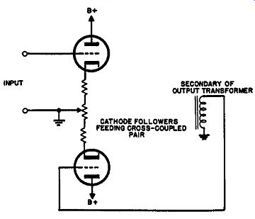
Fig. 423. Overall feedback connection for the cross-coupled inverter.
However, with all these advantages to the circuit, an amplifier designed around a push-pull inverter of this type at the front end makes a sort of deluxe basic unit as a toy for audio enthusiasts.
From a commercial design standpoint, the arrangement is hardly economic because it necessitates almost twice as many tubes in the power amplifier as well as the associated resistors that go with them.
Extra push-pull drive stages
Due to restrictions in the handling capacity of all the tube types of inverter, any of them may be followed by a push-pull stage of amplification feeding the output tubes themselves, especially where a complete or partial cathode-follower arrangement of output tubes is used.
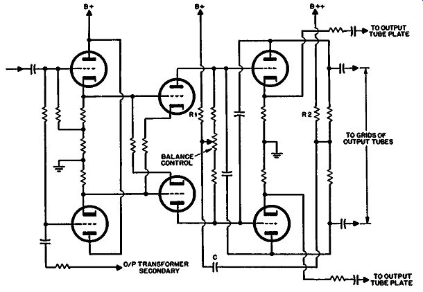
Fig. 424. Cross-coupled inverter showing how one low-frequency rolloff
parameter can be eliminated by direct coupling between inverter and driver
stages.
Sometimes the number of low-frequency parameters can be reduced to two, as shown in the typical cross-coupled arrangement of Fig. 424. The only coupling capacitors are the push-pull ones between the drive stage and output stage grid. These, as a single push-pull low-frequency loss, work in conjunction with the effective primary inductance of the output transformer-the only low-frequency-loss parameters. Similarly at the high-frequency end, the only loss points are at the grids of the output stage and the two elements in the output transformer, primary capacitance and leakage inductance. Capacitance effects at the plates of the drive stage are neutralized by the cross-coupled neutralizing capacitors.
Where there are two consecutive stages of push-pull amplification, it is possible to add a measure of self-balancing. To do this extra resistors R1 and R2 are connected, as shown in Fig. 424.
If there is any unbalance in the signal through the amplifier, part of the unbalance will appear across these resistors, but in opposite phase and at a difference in level because of the stage gain. Also any second harmonic generated by the half-channels will be added in these resistors, although the true push-pull signal will neutralize. By coupling the two together, the phase opposition reduces the magnitude of both out-of-balance components and second harmonic generation, in the manner of normal negative feedback action, using the second stage as a push-push-coupled arrangement while the wanted signal component is in push-pull.
The effective amount of feedback available for this purpose is not as big as may appear at first. The signal from the tie point of R2 is fed back through the capacitor to the grid circuit, where it is attenuated by the individual plate resistors in series and the plate resistance of the previous stage in shunt. From this viewpoint it is better to couple to the tie point of the previous-stage plate resistors rather than to set up a similar junction in the grid circuit (where R-C coupling is used-this cannot be shown in Fig. 424, which uses direct coupling at this point) because the grid resistors are usually larger than the plate resistors hence would provide less effective feedback of what is sometimes called "longitudinal feedback." The inner feedback loop, shown from each output tube plate to the cathodes of the driver stage, actually has three low-frequency parameters, due to the additional blocking capacitance necessary here. However the values can be adjusted to avoid peaking in this internal loop. The overall feedback loop-unusual as it may be-has only two parameters contained in it apart from any peaking that may be introduced by the inner loop.
From the viewpoint of feedback amplifier design, the two feed back loops (here regarding the push-pull inside one as a single loop) should really be designed complementary. The inner loop has only two high-frequency parameters, the grid-to-grid and plate to-plate capacitances of the output tubes. The latter includes the primary capacitance of the output transformer. Then the overall loop includes one extra reactance, the leakage inductance of the output transformer.
At the low-frequency end, care needs to be exercised more particularly on the inner loop because this uses three low-frequency reactances. Once this has been rendered adequately stable with a good rolloff margin, the outer loop does not present problems because the effective reactances here will only be two-provided the inner loop has been satisfactorily taken care of.
Positive feedback drive
Now we come to a particular type of drive stage in which positive feedback is used to help get the necessary swing from a relatively small tube at a low plate voltage. This kind of arrangement can be used with the Circlotron or unity-coupled arrangement or any type of amplifier where there is a high push-pull voltage at the plates of the output tubes and a comparable push-pull drive required at the grids.
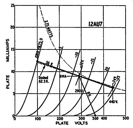
Fig. 425. Positive feedback increases the drive obtainable from the
12AU7.
Using the Circlotron circuit, let's pursue the possibility of using a 12AU7 with a plate supply voltage of 360. The appropriate characteristics are shown in Fig. 425, a suitable operating condition that will just about give the required swing using an 8,000 ohm resistor and a bias of 12 volts. This gives an operating condition of 290 volts on the plate at 9 ma of plate current. So the bias resistor will need to be about 130 ohms and the operating point close to the maximum dissipation of the 12AU7 as well as its maximum plate working conditions-2.75 watts and 300 volts, respectively.
When the output stage has its correct plate load, the effective positive feedback is 7.2. Using, for convenience, the round figure of 7, this means the effective plate load resistance, through the operating point, will be about 56,000 ohms. Drawing this load line and estimating the swing for an input from zero to -24 volts, we find that the plate swings from 290 to 100 and up to 440 volts.
A peak-to-peak swing of 330 volts is necessary, so this arrangement gives a working margin of 10 volts.
If the plate load resistance of the output stage should be larger than its nominal value, the swing required at the grid will be increased correspondingly. This means also that the positive feed back will be increased proportionately. However, from the load line in Fig. 425, increasing the slope does not proportionately increase the length of the load line at this point. Consequently the use of a load higher than the nominal value on the output tubes, will mean that this tube will no longer be capable of providing the necessary swing.
Table 1. COMPARATIVE QUALITIES OF PHASE INVERTERS
* Number given indicates number of rolloffs contributed by the phase-splitter part of the circuit only. In this column, ½ indicates a rolloff in one side of the phase inverter but not In the other.
Distortion figure given only indicates the contribution due to individual curvature of phase-splitter tubes, assuming identical types, where more than one is used.
O/P = output; V /A= voltage amplifier; L/F = low frequency; H/F = high frequency.
For this reason a better tube, such as the 12BH7, which can utilize a higher plate voltage, is an advantage. The pentode at the output can also use a higher supply voltage but there will be an overall gain, providing a better margin.
But, just to complete the picture, assuming the correct nominal load is used, let's continue the figuring for the 12AU7. The swing produced by each half is 190 volts in one direction and 150 in the other. Thus there is an off-center effect of 20 volts in a peak-to peak of 340 volts, representing about 6.2% second-harmonic distortion. However this 6.2% will be in opposite phase on the two halves of the push-pull driver stage and, other things being equal, will cancel at the plate circuit of the output stage.
However the fact that it will interact with the distortion of each output tube, which also will possess some nonlinearity of an opposite kind, will complicate matters somewhat and tend to produce higher-order-harmonic components of somewhat lower level.
This assumes that the positive feedback multiplies the actual plate load resistor by the factor of 7 as a linear multiplier. The nonlinearity of the output stage will mean that this factor of 7 is not constant so the load resistance applied to the 12AU7 will not be a constant resistor of 56,000 ohms. However, the fact that the load line is relatively horizontal will mean that the nonlinearity of its value will not add a proportionate nonlinearity to the output voltage.
The positive feedback will, however, multiply the residual distortion achieved by the output stage. In this particular example, the use of positive feedback between output and driver just off sets the negative feedback produced by the splitting of the output load. This means that we shall land back at a distortion figure of approximately 2% before any overall feedback is applied, as in the case of the tube with straight pentode operation.
While the position on the matter of distortion will be restored by this positive feedback to that without the negative feedback due to the cathode circuit, the same effect does not apply to the plate resistance presented at the output. Fig. 425 shows that changing the slope of the dynamic load line on the 12AU7 (such as occurs by removing the output load) will not materially affect the swing it delivers for a given grid voltage input. The plate resistance of the 12AU7 at the operating condition chosen is about 8,000 ohms and the load resistance is 56,000. Removing the output load, with a source resistance of 0.13 the load resistance will increase the output swing so the positive feedback factor changes from 7 to 7.8, which will raise the 12AU7 load line from 56,000 to 62,500. This will increase the swing delivered by the ratio ..., or about 1.2%, This change in drive will thus effectively increase the source resistance of 0.13 by 1.2% to about 0.132. So the effective source resistance of the output of a Circlotron or unity-coupled arrangement will still be less than 0.15 times the load resistance.
The distortion will be in the region of 2 to 2.5% so some over all feedback can be used for distortion reduction.
At this point the stability criteria of an arrangement such as this is quite simple to determine. The positive feedback utilizes--only the coupling between the plate and grid of the output stage.
The coupling from plate of the output to plate of the driver is directly through the plate load resistor. This being the case, there is only one rolloff parameter affecting both low- and high-frequency stability criteria. The presence of positive feedback will bring these rolloffs proportionately nearer to the passband while the negative feedback due to the cathode section of the load on the output tubes will correspondingly widen it. The net result will leave the working parameters approximately in the same position as with a pentode tube directly driven without these positive and negative feedback loops.
While the Circlotron amplifier (Fig. 426) has been used to discuss the merits of this kind of back coupling with a drive stage, the same principle can be calculated for other circuits.
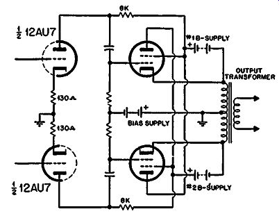
Fig. 426. Complete circuit of Circlotron output.
It should be mentioned that, as the tubes and operating conditions are not those of the amplifiers made by Electro-Voice (proprietary name, Circlotron), the figuring given in this guide does not represent the actual performance of Electro-Voice amplifiers.
Different figures have been used deliberately so as to provide a more definite comparison between the operation of the various circuit types considered. The Electro-Voice amplifiers use different tube types and operating conditions, optimized for the over all application.
Table 1 lists the comparative qualities of various types of phase inverters.