THE problems peculiar to input stages arise because the signals to be amplified are so very small. This is aggravated by the dynamic range to be handled. Suppose a microphone or pickup delivers 2 millivolts of signal at the grid of the input stage. The rated input is probably somewhere near the maximum signal that it delivers: if the system handles a dynamic range of 60 db (which means the loudest signal is 60 db higher in level than the quietest), then the quietest signal-which should still be heard above background noises-will be in the region of 2 microvolts.
This is a very small value and it is quite easy to pick up various components of spurious signals, which come under the general classification of noise. There are two main regions to be concerned with in the input stages. First, the input circuit itself, before any amplification occurs, and second, the way in which we amplify until the signal is big enough not to be bothered with noise problems.
In the academic sense noise is any unwanted signal. It can be classified into three groups. The first is random noise, which may be described as a random sequence of charge movements (due to the random behavior of electrons) which produces sound characterized by hiss. Actually, random noise is distributed throughout the entire spectrum but, because the ear is more sensitive to frequencies above 2,000 Hz, the sound we associate with this kind of noise is hiss. If the noise is passed through a filter that emphasizes the lower frequencies at a slope of 6 db per octave or more, then the hiss gives place to more of a roar. In fact, random noise can be colored by passing it through an electronic filter to give almost any effect we may choose. Sending it through a narrow tuned circuit of, say, 500 Hz gives a sound very similar to a person whistling that particular tone.
When the word "noise" is used without other qualification, more often than not random noise is the form intended. Some times it is used in its more academic sense to include all forms.
The second group of noise or spurious signals is hum or other forms of stray pickup. Cross-talk from an undesired program source would come under the same general grouping, but norm ally in audio work the problem is hum from various stray supply fields.
The third is microphony. This is most commonly associated with the input tube and causes it to emit a "pong" sound in the output when tapped with a pencil or the finger.
However, there are other forms of microphony such as that which occurs sometimes with an input cable as, for example, with the lavalier type mike worn on the chest of the speaker. The cable runs over the speaker's clothing and, if special attention is not given to obtaining a grade of cable free from this effect, any movement of the speaker is accompanied by a kind of rubbing noise picked up by the cable itself. 'While some of this noise may be transmitted mechanically or acoustically to the microphone as a transducer, some of it is picked up in the wire electrically.
Input circuit thermal noise
The first thing to appreciate about noise of the random variety is that there is a basic minimum due to thermal or temperature effect. This is a property of all resistance materials. It can be expressed as a noise voltage, which means the rms output voltage produced by any resistance is given by the expression
en= y4KTfR
where K is Boltzmann's constant (Joules per degree Kelvin), T the temperature in degrees Kelvin, f the bandwidth in Hz and R the value of the resistance in ohms.
For an everyday formula, since we will not be bothering with a wide range of temperatures, the following approximate formula can be taken, which avoids the repeated use of temperature and Boltzmann's constant,
en = yfR X 1.26 X 10^-10 volts
From this we can calculate and tabulate the effective noise voltage generated by different resistance values over various band- widths. Here is a second reason why random noise tends to sound more like hiss: most of the energy is concentrated in the higher frequencies. For example, there is as much noise energy between 5 and 10 kHz, which is one octave musically, as there is between 0 and 5 kHz-all the frequencies below this octave.
This basic thermal noise is a minimum in any circuit. Some times there will be a greater noise than this-current flowing through a resistor, for example, may produce additional agitation or fluctuation in the current path. For this reason it is important to exercise care in selection of resistors for input circuits. They should be of particular low-noise or high-stability construction.
The regular composition resistors are more noisy than the figures indicated in Table 1.
Table 1. R. M. S. NOISE VOLTAGES (IN MICROVOLTS) AT NORMAL TEMPERATURE (THERMAL COMPONENT ONLY)
It does not matter what form the resistance takes, the noise given by the thermal noise formula will still occur. It may be due to the resistance of a voice coil or the windings of a transformer or even the transformer core losses referred as a shunt resistance.
All these sources produce thermal noise.
A stepup ratio in a transformer increases the noise voltage by the same ratio that it transforms the signal voltage. This would naturally be expected, but the result is the same as if a higher resistance source were used. Suppose a 50-ohm voice coil is trans formed by means of a 40-to-1 stepup transformer and the band width is 10 kHz. The 50-ohm voice coil generates .092 p.v of noise.
A 40-to-1 stepup from this raises the level to 3.7 p.V. An 80,000 ohm resistor, which is the effective resistance presented on the secondary of a transformer giving 40-to-1 stepup from 50 ohms, also shows a noise voltage of 3.7 p.v. So the noise presented on the secondary is the same as if an 80,000-ohm voice coil had been used in place of the actual 50-ohm unit.
The only increase in noise that the transformer can produce is due to any resistance it may add of itself. For example, if the transformer is 80% efficient, measured by power-transfer efficiency (a typical value for a small input transformer), then 20% of the noise energy produced on its secondary side will be from the transformer and 80% from the actual input source. This means there will be a 25% increase in noise energy, or about 12% in crease in noise voltage, relative to the signal voltage, due to the use of the transformer.
So the essential features of the input circuit, from the view point of resistance noise, are:
1). Any necessary resistors, such as the feed resistor for a carbon or a capacitor microphone, should be of a low noise type.
2). The attenuation effect of resistors should be a minimum; the efficiency of a transformer should likewise be a maximum.
This means that gain control, where the input is at a low signal level, should be effected after some amplification has raised the signal to an adequate margin above the noise level. This does not apply to inputs where the signal level is well above noise level in the first place.
Hum
Hum can be picked up by one of two kinds of field inducing it: either a magnetic field causes electromagnetic induction in the input circuit or a static field causes electric induction. Technically, both forms produce a voltage but it is simpler to visualize the behavior by thinking of electromagnetic induction as producing a current and electric induction a voltage.
Electromagnetic induction is more readily noticed in low-impedance circuits. It requires a completed loop in which to induce a voltage. If the connecting lead for a 50-ohm microphone picks up a magnetic field from the supply, the field will induce a few microvolts (or millivolts, according to intensity and the size of the pickup loop in the input circuit). When this input circuit is stepped up by an input transformer, the voltage induced on the primary side will be multiplied by the ratio of the transformer (Fig. 501).
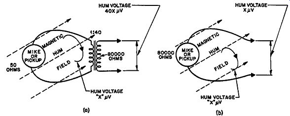
Fig. 501. Electromagnetic pickup of a magnetic hum field is more serious
in low-impedance circuits. The same voltage is induced in the same wiring
loop, whether the impedance is 50 ohms (A) or 80,000 ohms (B). But the
input transformer steps up the hum voltage as well as the signal, at
A.
In a high impedance circuit, say 80,000 ohms, the same magnetic field would still induce only the same voltage as in the 50-ohm circuit. So use of a 50-ohm circuit followed by a stepup transformer results in induction of 40 times the voltage as far as the amplifier is concerned.
Electric induction induces a charge and, if the impedance of the circuit is comparatively low, the charge will be conducted away almost as rapidly as it is induced. Consequently, electric induction is most effective in causing trouble in high-impedance circuits.

Fig. 502. Electric induction, normally only troublesome in high impedance
circuits, sometimes cause's trouble in low-impedance circuits.
There is, however, a particular way in which it can cause trouble in low-impedance circuits, too (Fig. 502). If the low-impedance circuit is not connected to ground, then the electric field will induce a like voltage in the entire circuit-both sides of the low impedance line. This will not be transferred to the secondary of the transformer by normal transformer action but, if there is some capacitance between the primary and the high or hot side of the secondary, electric transfer may occur from the low-impedance circuit to the high side of the high-impedance circuit, without true transformer action.
In this simple case the trouble can be cured very simply by grounding the low-impedance circuit. Technically, it should be grounded to a center point to obtain perfect neutralization of any pickup of this nature. But, in practice, grounding either side will be almost equally effective. If the electric induction is very in tense, it may be of advantage to ground the center point either by using a tapping on the transformer primary or by putting a potentiometer across the primary and adjusting for a null (Fig. 503).
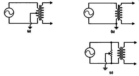
Fig. 503. Cures for the trouble of Fig. 502. The low-impedance winding
should be grounded. a-- ideal arrangement, connecting through a center
tap. b-where there is no center tap, connecting one side to ground is
often as good. c-an artificial center tap.
However, sometimes the low-impedance circuit has a ground.
Maybe there is a connection between the program source and the amplifier, and the former is already grounded. There may be an appreciable hum voltage between the ground of a program source and that at the amplifier. Where grounds are separated by physical distance this is almost a certainty. Under these circumstances the electric field will be set up between the primary and secondary of the input transformer and there will be a considerable electric pickup of l}um in the amplifier.
This requires special attention to the input circuit. One means of overcoming the difficulty is to use a line transformer to isolate the low-impedance winding from the input transformer itself.
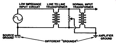
Fig. 504. Correcting for electric induction caused by unavoidable separate
grounds.
Then the intermediate circuit can be grounded back to the am-p1ifier ground (Fig. 504). In this case it is advisable to p1ace a potentiometer across the intermediate circuit and adjust for a null in the electric pickup transferred.
Choice of impedance
Where fairly long connections of, say, more than 200 feet, are used between a microphone and an amplifier, it may be desirable to use a line-impedance connection because a low impedance, such as 50 ohms, will be susceptible to e1ectromagnetic induction while a high impedance wil1 be susceptible]e to electric induction or high-frequency Joss. The middle impedance, in the region of 250 to 600 ohms, is an ideal compromise for such long-distance circuits.
For relatively short distances, up to 100 or 200 feet, the use of this special line impedance is hardly necessary. When using a low impedance, say not higher than 50 ohms, the circuit can be run either in concentric cab1e-that is, a single shielded wire-or in a fairly tightly twisted pair. This will obviate the loop effect that causes magnetic induction. Either of these are better than twin shielded wire where the twin is flat and not twisted. The shielding on a twin shielded has little effect on the magnetic field so the parallel pair still makes an overall loop effect.
For long-distance line-impedance connections, twin shielded should be used and the circuit should be balanced; that is, center tapped to ground, at one end preferably. The twin shielded should use a twisted arrangement inside the shielding.
High-impedance input connections should always be in single shielded, preferably in some kind of low-loss or low-capacitance per-foot type of cable. The shunt capacitance introduced by the connecting cable results in loss of high frequencies in a high impedance circuit. There is one exception to this-when a capacitor or piezo-electric type of transducer is connected.
In an input circuit that uses a transformer, this invariably will need shielding, particularly against magnetic hum fields. Any magnetic hum field that reaches the core of the transformer wi11 induce voltages in the transformer secondary, just as current in the primary will.
Two kinds of shielding are effective against a magnetic field.
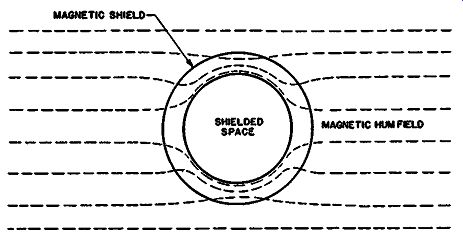
Fig. 505. A high-permeability magnetic shield protects the shielded
area.
The magnetic shield, which provides an alternative path around the transformer for the magnetic field to follow, is shown in Fig. 505. The essential feature is that the shield shall fit well to provide a uniform path so as not to introduce a further leakage field in- side the shield. The shield must be of high-permeability and high resistivity material so that fluctuations in the magnetic field are not delayed by the shielding material. For this reason the shield is most effective at low frequencies.
Some hum fields, particularly those due to full or partial saturation in a power transformer, contain components of 180 Hz and even higher frequencies as well as 60 Hz. While the magnetic shield may be quite effective against 60 Hz, it is not so effective against the higher-frequency components. So a well shielded input transformer must utilize another kind of shield to guard against the higher frequencies.
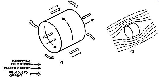
Fig. 506. Electromagnetic shield. a-principle of generating an opposing
field. b-resultant field pattern.
This is the electromagnetic shield (Fig. 506). The changing magnetic field induces currents in the conducting material of the shield. These currents in turn induce a field opposing the original field inside the area shielded. At the same time they augment the field outside the area shielded. But the effect depends upon the changing of the magnetic field rather than on conducting the magnetic field itself and for this reason is more effective at higher frequencies.
A combination of the two in an arrangement shown in cross section in Fig. 507 provides an effective shielding for an input transformer.

Fig. 507. Where large amounts of shielding are necessary, a … more effective
than one heavy shield.
Cable microphony
Before we leave the input circuit we must discuss the features that make for cable microphony. The principal cause is change in shield resistance. This means that return currents in the outer conductor or shield of the connecting cable can be modulated by · movements that fluctuate the resistance very slightly. This is why body movements of a speaker wearing a lavalier microphone can cause sound to be induced in the cable.
The only way to eliminate this is to use cable that is relatively insusceptible to this effect. The best type is one which uses a twisted rather than braided shield. The braided shield makes a large number of relatively high-resistance contacts between the crossing shield wires. It is also not 100% effective in providing electric shielding because any woven braiding inevitably has air spaces between the wires where they cross.
A twisted shield wrap can be arranged so that all the conductors lay closely side by side and produce a much more effective covering. It might be thought that this arrangement would be inductive but this is prevented by using a single straight conductor in side the shield which short-circuits its successive turns. This it does much more effectively than the braided variety and produces a quieter form of microphone cable.
Also quite effective is the conducting-cotton variety in which the shielding material is cotton made relatively conducting by special treatment. This is wound in a similar manner to the shield just described. This is even more flexible than the wound shield and provides quite effective protection against microphony, if it is well constructed so that the copper connecting wire provides good contact at all points with the conducting cotton.
Input stage noise
Passing from the input circuit, we come to the first stage of amplification. This will add its quota of noise to that already present from the input circuit. In the input stage we have a number of conflicting factors with respect to the choice of tube for producing the lowest resultant noise in the output. The straight triode tube has a noise due to thermal effects given by the equation
Rn= 2.5 gm
This expresses the noise in terms of an equivalent resistor connected from grid to cathode or grid to ground of the input circuit, gm being tube transconductance in amperes per volt.
As an example, a 12AX7 tube is quoted as giving a gm of 1.25 ma per volt (1,250 µmhos) with a bias of -1 volt and plate voltage of 100. This means its equivalent noise resistance will be .o~·; 25 = 2,000 ohms. Note that the gm at the operative condition actually used must be taken, as the value changes for different operating conditions.
If the value of the resistor comes out higher than the resistance of the input circuit, then the noise from the tube will be more than that from the input circuit. If the equivalent resistance produced by the tube is lower than that of the input circuit, then the tube noise will be below that of the input.
If the input impedance is stepped up to the region of 80,000 ohms, any audio tube would have a noise figure well below this so that the controlling feature will be the input source. However, sometimes it is desired to avoid the use of an input transformer, and the source resistance of the pickup, or whatever the input comes from, may be in the region of say 5,000 ohms. In this case the equivalent noise resistance of the input tube may not be very much lower than that of the input circuit itself, so the choice of tube can become important.
If a moving-coil pickup cartridge with a resistance in the region of 100 to 500 ohms is used without any transformer, then the tube will definitely be the limiting factor as to input noise.
Associated with choice of a low-noise tube is the question of gaining sufficient amplification to get the signal above noise that may be introduced in components before the next stage. For example, the plate-coupling resistor has to carry current and the passage of current causes current noise in the resistor. Even though a good brand of resistor for this purpose is chosen, the noise generated will be greater than the thermal noise for the same value resistor. This means that the first stage should have as much gain as possible to lift the signal level above the noise likely to be generated between the first and second stages.
Pentodes give better gain than triodes but suffer from a higher equivalent noise resistance. They have an additional form of noise which occurs because the electron stream inside the tube randomly fluctuates between screen and plate. This random fluctuation produces a noise additional to that normally associated with a tube.
The control grid does not cause a similar variety of noise for the reason that its potential is kept negative, hence electrons do not strike the control grid. All the electrons leaving the cathode of a triode tube, under normal operation, proceed to the plate under the influence of the control field from the grid.
But in a pentode, the screen or second grid operates in two ways.
Its voltage provides a field that controls the course of the elections and also, due to the fact that it is positive, attracts some of the electrons to hit it. Some of them will try to reach the screen and just miss, continuing their journey to the plate. This means that a pentode is an inherently more noisy tube than the triode.
This partition noise, as it is called, can be reduced by designing the tube in such a way that the screen grid is in a kind of shadow from the control grid and so receives a small proportion of the total cathode current. But there is a limit to the possible reduction in this manner and the pentode is still more noisy than a triode.
The next best thing, then, would appear to be a high-slope triode. This should yield a low equivalent noise resistance and at the same time magnify the signal sufficiently to be above possible noise generation in the plate circuit and the following stage.
Microphonic tubes The difficulty here is that a high-magnification triode tube also has a much greater tendency to microphonics. The measures adopted by the tube manufacturers in reducing microphony can be used but they will be less effective on a high-slope unit. Any vibration reaching the electrode structure will be much more effective in generating fluctuating signals than it would on a low slope tube.
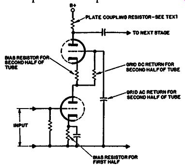
Fig. 508. Essential components of a cascode input circuit.
A useful compromise is the cascode circuit (Fig. 508). This virtually uses a twin triode as an amplifier and impedance multiplier to get a gain comparable to a pentode from the two tubes. It avoids the use of a plate-coupling resistor for the first tube, which feeds directly into the second tube.
The impedance presented by the cathode of the second tube as a plate load for the first depends upon the plate-coupling resistor used in the second. Assume a tube such as the 12AY7, which has an amplification factor of 40 and an average plate resistance of 25,000 ohms. Suppose we use a plate-coupling resistor of 100,000 ohms in the upper tube. The working gain of the upper tube will be 40 multiplied by 100/125, or 32. The grid-cathode swing will be 1/32 times the plate-cathode swing, for the same current swing. As the plate-cathode swing is related to the current swing by the coupling-resistor value, which we have chosen at the moment as 100,000 ohms, the effective resistance seen at the cathode will be 100,000 divided by 32, or about 3,000. This is the load, or coupling "resistor" as it were, for the lower tube.
With an amplification factor of 40 and a plate resistance of 25,000 ohms, the lower tube will now produce a gain of 40 times 3/28, or about 4.3. The overall gain of the double tube thus is 4.3 X 32, or 137.
This will give plenty of amplification to the input signal by the time it reaches the second plate so that noise in the plate coupling resistor is not likely to contribute appreciably. However, the noise of the second half tube may contribute an appreciable component because of the low gain achieved by the first, especially as the grid circuit components of the second half may generate a little noise-principally the capacitor coupling the grid to ground.
But increasing the plate-coupling resistor can raise the overall gain of the two stages to a much greater extent than it would with the simple triode stage, using a tube with the same plate resistance.
Assume that we increase the coupling resistor from 100,000 to 500,000 ohms. The gain of the second half of the tube then be comes 40 multiplied by 500/525, or about 38. This is not a very large increase, but the grid-cathode swing is now the plate-cathode swing divided by 38, which means the effective load resistance for the first tube is now 500,000 divided by 38, or approximately 13,000 ohms. This will improve the gain of the lower tube to 40 multiplied by 13/38, or approximately 14, in place of the previous value 4.3.
So increasing the plate-coupling resistor of the upper tube from 100,000 to 500,000 ohms increases the gain of the lower tube from 4.3 to 14 and of the upper tube from 32 to 38-an overall increase from 137 to 532. This means an approximately 10-db improvement in signal-noise ratio at the grid and cathode of the upper tube as well as in its plate circuit. Thus, where the limiting factor is the noise in the tube, a cascode seems to offer the best answer.
The best solution for microphonics in input tubes is to select a type deliberately designed to produce low microphonic effects.
If a tube is used in which particular attention has not been paid to this feature, although you may be lucky with one particular tube, you may find that the circuit will seriously deteriorate when the tube is changed and you may have considerable difficulty in obtaining a second satisfactory tube.
Tube hum
Tubes can also be responsible for injecting hum into the circuit.
The power supply can be responsible too. See to it that the B-plus supply to each tube is adequately filtered so that no ripple is in jected at this point. This can easily be checked by shunting across additional filtering to test whether this is where hum comes from.
There is a variety of other causes of hum originating in tubes.
One that should be obvious but sometimes gets overlooked is a satisfactory ground connection to the heaters or filaments. If an ac supply is used for this, a center-point ground is desirable al though modem tubes have been so well designed to minimize hum pickup from the heaters that sometimes little difference is noticed so long as the heaters are effectively grounded. The kind of hum caused by not grounding the heaters is produced by electric induction due to capacitance transfer from other windings in the power transformer.
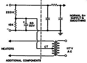
Fig. 509. Modification to a supply circuit to minimize some kinds of
heater hum trouble.
Another form of hum is caused by the heater acting as a cathode, as well as the true cathode. The cathode-heater insulation prevents the emission from the heater from joining with the normal cathode emission. But the heater usually has a small free space at the ends where it enters and leaves the cathode, and electrons emitted at this point may find their way erratically into the tube electron stream. Since the voltage on the ends of the heater fluctuates at the 60-cycle supply frequency, these stray electrons will be modulated and thus induce a hum in the circuit where the electrons land, probably the plate of the tube.
A way to minimize this is to provide a slightly positive potential on the heater, superimposed on the supply voltage. This should be about 25 volts and can readily be provided (Fig. 509) in the power supply. The heater bias point should be decoupled to ground by a large electrolytic to avoid electrical transfer. This avoids heater emission hum induction by insuring that the heater, instead of acting as an emitter, acts as a secondary plate or diode for some of the electrons emitted by the cathode. While electrons are busy transferring from the cathode to the heater, because the heater is at the more positive potential, there will be no trouble with stray electrons going from the heater to the plate.
There is one more possible cause of hum being induced in an input stage tube. This is a magnetic field that modulates the course of the electrons. If the hum field comes from outside the tube, the simplest cure is to provide the tube with a metal shield. This will usually minimize the effect down to where it cannot produce any noticeable hum injection.
Sometimes, as a precaution against the ac field from the heater, it is advisable to provide a de supply for the heater. A few years ago this was almost a vital precaution with high-gain amplifiers using very low input. But with modern tube developments, the advantage gained by de operation is almost negligible. Heater construction now allows for ac operation without appreciable hum field being radiated inside the tube. However some designers still prefer to use de operation as a final precaution against tubes which might be slightly defective in this regard, while functioning perfectly otherwise.
Distortion
This section has concerned itself with the low-level aspect of input stages, by far the most critical one. However dynamic ranges being what they are, sometimes the upper level can also be a consideration. Distortion must be taken care of in the input as well as the output stages of an amplifier.
One does not normally think of a low-level input stage as requiring feedback to reduce distortion because the amplitude of swing is so small that the tube curvature is negligible. Generally speaking, it is not advisable to use feedback over a low-level in put stage because it will increase the resultant noise.
Random noise or hiss is the only thing that feedback does not reduce in proportion to the reduction in gain. Any amplifier has a restricted frequency range, hence a phase delay, so it is im possible for the noise to be fed back exactly in antiphase with the generated signal. This means that complete cancellation of the noise is impossible with feedback. The noise generated in the feedback amplifier tends to be concentrated at the higher frequencies because cancellation of the lower-frequency components is more effective.
However, the fact that the input stage does not use feedback may mean that it will become the limiting factor for distortion because negative feedback can reduce the distortion of the later stages, which would otherwise be much greater. Early stages can produce quite appreciable distortion even with inputs of a few millivolts. In fact, measurements of distortion seem to show that tubes suffer from a sort of "hysteresis" effect like magnetic materials.
The hysteresis of a magnetic material limits minimum distortion to the region of 1% of the magnetizing current. Except at the lowest frequencies, the magnetizing current is a very small fraction of the transfer current. Actual distortion due to an input transformer is far below 0.1 %, except at the bottom end. This is a good enough reason why some try to do without an input transformer.
With tubes, the apparent hysteresis effect is always much lower than 1%-usually nearer the region of 0.1 %, But the fact that all tubes seem to have a minimum distortion figure when level is reduced suggests that it is well to select a tube type that has a good minimum distortion figure. This information is not generally published--or very often even known. The only way to find out is to make measurements with a good distortion-measuring set.
Several samples of each tube type should be tried to get an aver age and determine what "spread" can be expected.
This is also an argument for achieving as much gain in the first stage as possible so as to get out of this distortion-generation trouble (at higher levels distortion can be reduced more effectively by feedback) as well as getting away from background noise.
Intermediate stages
We also need to consider the intermediate stages between the first input and the phase splitter. Each of these needs to be de signed with adequate gain and at the same time with sufficient "headroom" or amplitude-handling margin to avoid running into distortion throughout the dynamic range that the stage has to accommodate.
In a "straight" amplifier where every stage handles a signal larger than the one before it, there is little likelihood of running into distortion before the stage ahead of the phase inverter. However, when a volume or gain control is used in the amplifier which inevitably has to be put somewhere--it is not impossible for some stage before the volume control to be operating at a higher level than the stage following it.
If the control is likely to be worked toward its "bottom end," this feature should receive special attention. If the input of the amplifier is expected to receive a wide range of input levels-from a few millivolts up to perhaps almost a volt--we have conflicting needs to meet. In the interest of achieving a low noise level for the low-level signals, the volume control would be put after the second stage (Fig. 510). While this would be an optimum position for low-level input, a high-level one will produce so much swing at the second stage as to cause distortion, although the volume control may be quite capable of controlling the overall gain so as to give a reasonable output level.
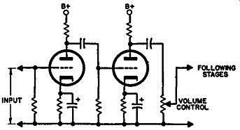
Fig. 510. For very-low-level inputs, the best place for a volume control
is after the second stage or later.
The only way in an amplifier of this type is to provide a ganged volume control. To get the best results, complimentary tapers should be used in the control so that, for low-level input, most of the controlling is done after the second stage or maybe even later in the amplifier, while for high-level inputs most of the controlling is done after the first stage to prevent overloading at any later stage. Fig. 511 shows such a circuit, with the desired tapers for the respective volume controls to achieve a logarithmic control in the combined arrangement.
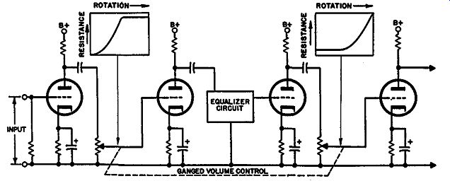
Fig. 511. A basic arrangement for a preamplifier required to accept
a very wide range of input signal.
While a logarithmic taper, such as used in the "active" position of each potentiometer, is quite customary, a control that is inactive for a portion of its rotation, as each of these are, is not usually a stock item and has to be made specially for such applications. If you are making only one preamp, it is better to design it with separate low- and high-level inputs.
Bootstrap pentode input
There is a particular type that once achieved considerable popularity-using a pentode in conjunction with the split-load type phase inverter (Fig. 512). It is well known that the pentode has a very high plate resistance.
A voltage-amplifying pentode may well have a plate resistance of several megohms with a transconductance between 1 and 1.5 ma per volt. This means that its amplification factor must be several thousand. But such amplification cannot be achieved in practice because of the necessity for using a reasonable value of plate-coupling resistor. It is not practical to use a coupling resistor of several megohms. Even if a high-voltage supply were used and the tube biased to operate successfully with such a high value resistor, the grid input capacitance of the following stage and stray capacitance would cause excessive high-frequency loss due to the fact that the source resistance at this point would be in the region of a megohm or higher.
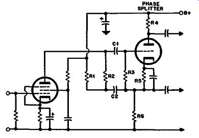
Fig. 512. Pentode bootstrap input stage.
The circuit of Fig. 512 makes use of this extremely high pentode gain by using what is actually a normal value of coupling resistor but increasing its effective value because it is virtually in the grid to-cathode circuit of the following stage. Resistor R2 serves as a plate coupler and is virtually in parallel with R3, the actual grid bias resistor, being coupled to it by C1 and C2.
Since the phase-inverter tube has a. 50% degeneration, due to R1 in parallel with R6 in its cathode, the effective value of all components connected between grid and cathode is multiplied by the gain of the tube as measured with grid to cathode for input and l(fid to ground as output. So if R2 is actually 220,000 ohms and R3 is 1 megohm, the combined effective resistance in parallel is about 180,000 ohms. If the phase inverter uses a medium-slope tube with a mu of 40 and a working gain with the resistors used of about 22, this will be a gain, with grid to cathode as input and cathode to ground as output, of 11, or a (1 + A[J) of 12. So the effect of the 180,000 ohms, from the viewpoint of the pentode plate, will be 12 times 180,000 or over 2 megohms.
With these values the pentode should give a gain in excess of 2,000. The circuit is completed by using R1 in parallel with R6 as the cathode load, since they are coupled together by C2 at the top end, and by R1 returning to B plus, which is decoupled to ground, at the bottom end. So, to get true balance in the phase inverter, the combined parallel resistance of R1 and R6 must be equal to R4 in the plate.
The high-frequency response is maintained because the effective grid-to-cathode capacitance of the tube is also divided by the same factor that the effective source resistance is multiplied by. So the high-frequency rolloff will be at the same point that would be produced if a 220,000-ohm resistor were used as plate coupling in the normal manner, with a I-megohm grid resistor for the following stage.
Provided this circuit is used with low-level input--which it would have to be with such phenomenal gain--the distortion is fairly low although operation of a pentode with such extremely high load resistance tends to produce distortion even at quite low levels.
The application of overall feedback in any quantity becomes somewhat of a problem with this circuit because of the extremely high impedances involved and a necessity for careful choice of coupling capacitors for C1 and C2. If these are made too large, they will result in excessive high-frequency rolloff due to their capacitance to ground. If they are not large enough, they result in partial removal of the multiplying effect produced by the feed back at the low-frequency end, hence result in the pentode stage losing gain down at these frequencies.
Capacitor C2 effectively provides a form of positive feedback, from the viewpoint of the pentode, although from the viewpoint of the phase splitter it is part of the negative feedback arrangement due to degeneration in the cathode.
The screen decoupling of the pentode adds a further complication with this method of operation. Under normal conditions removing decoupling of a pentode stage changes the effective gain of the stage, approximately from that as a pentode to a triode.
The effect of the decoupling capacitor is to introduce a step response at some low frequency, producing a phase shift similar to a rolloff but without the same degree of attenuation. It has a similar effect here except that the gain as a pentode is very much more than usual so the effect of deterioration in decoupling at the screen at low frequencies will reduce gain by a factor approaching to 100 to 1. This is almost the same as another low-frequency rolloff.
For a similar reason, if the decoupling circuit is at all inductive, it will produce deterioration of response at the high-frequency end due to the necessity for complete screen decoupling to achieve the high pentode gain realized.
Transistors
The use of transistors has provided another possible form of input stage and it is one that holds considerable promise of proving ultimately to be the best. When transistors were first introduced, they seemed to suffer from serious signal-to-noise problems but this was because they were not used under the best operating conditions. An advantage of the transistor circuit is that its input impedance can be made to suit the low input resistances normally used for the best microphones and pickups, without the need for a matching transformer. By careful choice of operating conditions, the distortion can be kept quite low and by working with a very low collector current the noise level can be reduced to a value that compares favorably with the best tube circuit. Also transistors are inherently free from hum and microphony troubles that are always present in some degree with tubes.