IMPEDANCE matching is necessary in audio circuits. There are two principal places for matching: at the input and output of an amplifier. In each, the purpose is to make an actual impedance look like the impedance required by the amplifier, as an optimum input or output impedance.
Input Circuits
In input circuits, matching arrangements change the actual in put impedance to a value that will give the best signal-to-noise ratio compatible with a suitable frequency response. As an example, a 50-ohm microphone working directly into an amplifier will not have a very good signal-to-noise ratio because the equiv alent noise resistance of the tube will be 1,000 ohms or more, about 13-db higher in noise level than that in the source itself.
A transformer to step up the signal to the grid of the first tube will improve this situation. It will also contribute some useful gain so that a smaller amount of gain is required in the amplifier.
This might solve some feedback problems. It is more difficult to get, say, 20-db feedback over an amplifier with higher gain than one with lower gain because the higher gain necessitates more stages and complicates the design. However, the use of too much stepup in the input transformer will deteriorate the frequency response--quite apart from that of the transformer itself.
Assuming that the transformer steps up the 50 ohms to 80,000 ohms, using a 40 to 1 stepup, then the microphone now looks like an 80,000-ohm resistor as far as the grid of the first stage is concerned. If the input capacitance should be as high as, say, 100µµ.f (which it might well be) including the secondary capacitance of the transformer, then the response will be 3 db down at 20 kHz because 100 µµf gives a reactance of 80,000 ohms at 20 kHz. If twice the stepup were used, (resulting in 320,000 ohms) the same secondary capacitance would cause the response to be 3db down at about 5 kHz.
Thus, the choice of stepup is a compromise between signal-to noise level and the frequency response required for a full range within close tolerance. Probably a 20-to-1 stepup with the 3-db point at 80 kHz will be considered an acceptable ratio.
The input transformer does not directly affect the low-frequency response unless the primary inductance is inadequate.
However, there is a way in which the amount of stepup does some times affect the low-frequency end. For a satisfactory high-frequency end with low leakage inductance and secondary capacitance, the winding has to be physically small. This means the transformer itself must be physically small. There is a limit to the fineness of wire with which the secondary winding can be wound, consequently there is a limit to the number of turns that can be used. The only way to increase step-up, when the limit of turns has been reached in the secondary is to reduce the number of turns on the primary, which of necessity also reduces the primary inductance.
Inductive sources
We have assumed the source impedance to be a pure resistance of 50 ohms. Many magnetic microphones and phono cartridges, however, possess quite an appreciable inductive component al though the nominal impedance may be given as the approximate resistance presented at a middle frequency, somewhere from 400 to 1,000 Hz.
Where the transducer (microphone or pickup) possesses appreciable inductance, it will be considerably greater than any leak age inductance that an input transformer will add. An input transformer designed for use with an inductive device does not need to have particularly low leakage inductance because the inductance of the source impedance will swamp it anyway. But this also means that a smaller capacitance can be tolerated on the secondary before the high-frequency-rolloff condition becomes severe and, therefore, that the effective stepup is correspondingly restricted.
In some instances it may be difficult to prevent the capacitance on the secondary of the transformer from resonating with the inductance of the source impedance. In this case the response will show a peak at the high-frequency end. To damp this peak with out risking deterioration of the low-frequency response apply resistance across the secondary of the input transformer (Fig. 601).
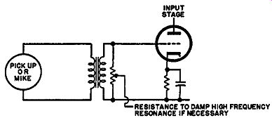
Fig. 601. Controlling high-frequency response through an input transformer
by using a loading resistance on its secondary.
Try different values until the optimally flat response is achieved.
If this results in a rolloff at a frequency lower than is considered satisfactory, then the only solution will be to use a transformer with less stepup.
Capacitive sources
Input matching also raises the question of suitable connections for capacitor and piezoelectric microphones and pickups. Here our thinking has to take into account the fact that the source impedance is no longer a resistance or a resistance combined with inductance but principally a capacitance (Fig. 602).
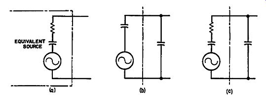
Fig. 602. Matching as applied to capacitor or piezoelectric transducers.
a--true equivalent source. b--an ideal matching arrangement, assuming
the source is entirely capacitive, giving response from zero to infinity.
c--the resistance in the actual source prevents the ideal of b from being
realized.
Working from a capacitive source into capacitive load will result in a flat frequency response from zero to infinity, in theory.
But there are always some resistance elements somewhere in the circuit to introduce losses and these will result in a rolloff some where in the frequency response.
The source usually looks like a capacitance with a little bit of resistance in series, due to the losses in the device and the dynamic loading. This results in a high-frequency rolloff. If the transducer is worked into a capacitance larger than itself, the high-frequency rolloff will be determined by the transducer capacitance and if into a capacitance smaller than itself, then the loading capacitance will determine the high-frequency rolloff point. Usually a resistance provides a grid circuit return for the input tube and this resistance (Fig. 603) results in a low-frequency rolloff.
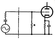
Fig. 603. Loading a capacitive source with a resistor R produces a low-frequency
rolloff, the frequency of which will be determined by relative values.
Optimum energy transfer from the source to the load occurs if the source and load capacitances are equal. This seldom hap pens but it is not feasible to use a transformer for matching here because the inductance and losses of the transformer result in impossible frequency response limitations before anything approaching ideal matching can be achieved. In practice, it is impossible to design a transformer that will achieve any improvement on the direct connection.
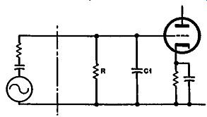
Fig. 604. In cases where the transducer gives plenty, if not too much
output, C1 is used to attenuate the output, so a lower value 'de grid-return
resistor R, can be used without undue low-frequency loss.
There is a particular application with the piezoelectric type of microphone or pickup that is sometimes useful. The output from these devices is relatively high compared to other transducers.
Consequently it may be too large in some instances for the input stage to which it will be connected. Also, to achieve a satisfactory low-frequency response a very large input resistor is required. But, by employing a large input capacitance (compared with the value of the source) a more suitable input resistance can be used without running into the low-frequency rolloff. Also the input will be attenuated into a region more suited for the amplifier (Fig. 604). To maintain the high-frequency response which, under these circumstances, would be limited by the relation between resistance and capacitance in the transducer itself, it may be necessary to add a component of resistance in series with the artificial input capacitance to maintain level response at the high end (Fig. 605).
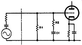
Fig. 605. If the arrangement of Fig. 60-1 results in high-frequency
loss, due to the equivalent resistance in the source, it can be offset
by a suitable value of resistance,
This would be a useful circuit for permitting a piezoelectric pickup, for example, to be connected to the input of a preamplifier intended for a magnetic or moving-coil type pickup. The only thing left here, however, is the fact that the crystal pickup is a constant-amplitude device while the magnetic or moving coil are velocity devices. There should be a 6-db-per-octave upward slope in the input circuit from the piezo pickup for the equalization provided in the amplifier for the magnetic or moving-coil cart ridge to be suitable for the crystal type. To achieve this all that is necessary is a considerably lower value of loading resistor on the input (in the circuit of Fig. 603) which produces a 6-db-per-octave bass loss from some relatively high frequency. This will amount to some 35 or 40 db attenuation at 1,000 cps. For this reason it will not be necessary to use the capacitive attenuation shown in Fig. 604.
With some capacitive transducers, such as the capacitor micro phone or the sound-cell crystal, the sensitivity is very poor and so it is necessary to make the best of the output available without introducing this attenuation effect. To achieve this a very high input resistor is required in the first grid. This will result in a relatively high background noise. A method of partially over coming this is to use some feedback over the input stage that will increase the effective input impedance, rather like a cathode follower.
The arrangement could be a cathode follower to act as an impedance changer or it could be part of the overall feedback arrangement (Figs. 606 and 607). In these circuits the actual grid to-cathode resistance can be much lower, utilizing the advantage of a lower input noise, but the effective value of resistance from the point of view of loading the transducer is increased by the de generation. This also decreases the capacitive loading presented by the tube input, which for these transducer types may well be equal to or greater than that of the source capacitance. The de generation, as well as increasing the effective load resistance, will also increase the noise to some extent. But degeneration does attempt to cancel some of the noise voltages generated although it is not completely successful. So the overall result is an improvement over using the actual resistance instead of the effective resistance produced by this degeneration.
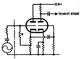
Fig. 606. Use of a complete cathode follower at the input to raise the
effective value of R for loading a capacitive source, without a corresponding
noise increase.
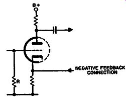
Fig. 607. An alternative way of helping raise the effective value of
resistor R is by negative feedback from a later stage, connected to the
cathode.
Output circuits
The usual reason for matching in output stages is the achieving of maximum output power for given operating conditions in each of the methods of tube connection. Whatever the reason for matching the optimum load resistance is invariably different from the plate resistance or effective source resistance of the stage.
For maximum efficiency as a power transfer device, the load 8+ resistance or impedance should be equal to the source resistance or impedance. This is based on a theoretical linear device with out any limitations. If tubes satisfy this condition, then the load resistance should always equal the source resistance. But unfortunately the value of source resistance, or plate resistance, of the tubes is only applicable over a certain range due to the curvature of the tubes and it is desirable to steer the load line away from this curvature to maintain linear operating conditions to the greatest possible extent.
Maximum power output
This is why triode operation, with curvature at the bottom of the line, requires a resistance higher than the working plate resistance so as to keep the load line more horizontal and away from the curvature. (Except, of course, when low loading is used, in which case the curvature of the two tubes in push-pull is used to cancel second-harmonic distortion and provide a bigger output.) In the case of pentodes, the curvature is toward the top or left hand end of the tube characteristics. A more vertical load line than the slope of the characteristics proves satisfactory to avoid the curvature at the left-hand end.
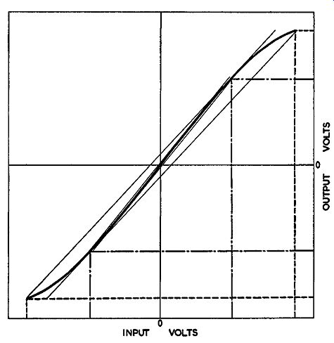
Fig. 608. A transfer characteristic with "one-way" curvature
results in lower distortion at lower levels. Input and output swing at
maximum level is indicated by dashed lines, at lower level by dot and
dash lines.
Minimum distortion
This is not the only condition to be considered for deciding correct matching in an output stage, however. Closely associated with the load value for maximum power is the value for lowest possible distortion. Distortion is usually considered on the basis of maximum output. However, distortion at maximum output is less noticeable than distortion at somewhat lower output. Consequently, amplifiers are sometimes designed to give the lowest possible distortion at relatively low levels, allowing the distortion to become a little higher at maximum output.
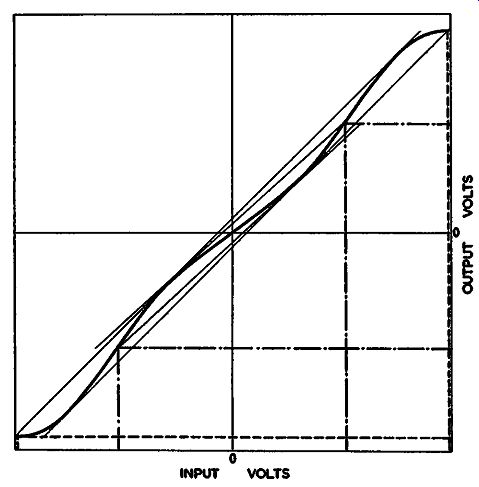
Fig. 609. A transfer characteristic with several reversals of curvature
may result in lower magnitude of distortion (but higher order) at maximum
level (dashed lines); but higher magnitude (lower order) at lower levels
(dot and dash lines).
This is another reason why the circuits which produce mainly low-order distortion are better than those that produce high order distortion. (Do not confuse order of distortion which indicates whether the harmonics caused are high or low, with amount of distortion, given as a percentage figure.) The circuits that produce lower-order distortion use tube characteristics with a simple curvature resulting in either second or third harmonic. Consequently the distortion reduces as the length of the load line is reduced, representing lower levels, and the order of distortion remains the same (Fig. 608). Also with this kind of curvature the slope of the load line, representing its impedance value, remains very close to the same angle for minimum distortion at different levels.
But the kind of curvature given by pentode operation, which produces recognizable quantities of fifth and also seventh harmonic, results from a transfer characteristic that has multiple curves (Fig. 609). The distortion at full amplitude contains components of fifth and seventh harmonic, due to the multiple curvature. But as the excursion is reduced, the curvature simplifies and so the order of distortion is restricted to the lower harmonics.
However, the magnitude of the distortion may actually increase under these conditions at lower levels, since the multiple curvature reduces the effective components of low order at high amplitude.
This cancellation does not occur at low amplitude and we may be left with a higher percentage of low-order harmonic distortion.
Readjustment of the loading condition may result in improved distortion at low levels although it will aggravate it at high levels.
This is another good reason for avoiding straight pentode operation.
A final feature of matching is the effect of feedback as a source or load modifier. For example, to give a constant output, the electrostatic transducer should have a constant voltage. This means that the source impedance should look like a capacitance or else some means should be undertaken to provide constant voltage across the variable reactance presented by a capacitance load.
For this reason the power amplifier feeding an electrostatic transducer must be designed on the basis of much larger power output-or perhaps we should say volt-amp output (because the load is almost entirely capacitive reactance) than would be necessary for the regular type of transducer.
Transistors
When a transistor is operated in grounded emitter connection, it behaves very similarly to a tube. It amplifies both voltage and current, and produces a phase inversion. Practically all the present circuits for application in audio use grounded emitter operation.
One reason for this may be that it avoids too many new concepts by enabling the transistor to be visualized as a "tube replacement." However an analysis of other methods of connection also seems to show definite performance advantages.
The transistor is basically a current-operated device, whereas the tube is voltage-operated. This is important because each kind of amplifying unit has its nonlinearity, or curvature. In a tube, the departure from linear amplification is related to voltages handled. In a transistor, it must be related to the currents.
This fact is reflected in a consideration of matching for transistor circuits. For tube circuits, we think of a voltage generator with a series resistance as our source of input. For transistor circuits it is more convenient to translate this into a current generator with a shunt conductance or susceptance. The important quantity delivered to the transistor is not the voltage fluctuation, but the current fluctuation.
This is complicated by the necessity of providing the correct bias for the transistor. The operating temperature of tubes is not a critical factor, and is principally determined by the heater dissipation. So long as electrons are emitted by the cathode in adequate quantities, the temperature has little effect. But in a transistor, change in ambient temperature alters the characteristics considerably. The circuit must be designed so that change in temperature does not interfere with operation.
There are two approaches to this problem: one is to compensate for the known temperature characteristics of the transistor, using diodes of similar material, or temperature-sensitive resistors. What would seem to be the better way uses a de feedback circuit that adjusts relative voltages in the base-emitter circuit to obtain the right operating range of collector current (and thus base current). This has the advantage that it will also care for deviation in individual transistors as well as temperature effects.
So, particularly in a transistor input circuit, the ac susceptance or impedance must be right to give the required frequency response and to minimize distortion, while the de conditions must maintain correct operation of the transistor. This subject becomes quite an involved one, and the number of ways of doing it promises to exceed the variations in tube circuits; so it cannot be treated in detail here, and is definitely beyond the scope of this guide.