DAMAGE to tubes and other components during or as a result of servicing tube troubles means lost time and increased service costs. A higher bill to the customer may be necessitated, making his emigration to a less expensive competitor a possibility.
It is obviously desirable that such damage be avoided. What to do in all cases to avoid such damage is, however, not quite so obvious, particularly to the inexperienced.
This section will discuss common, as well as not-so-common, sources of damage to tubes and other components. Enough in formation will be presented to enable the reader to minimize costly service errors.
Tube mountings
There are a number of considerations with regard to the positioning of tubes that the service technician should know. Technicians sometimes operate receivers--particularly intermittent ones--for long periods of time. In other instances, they may add one or more tubes to the set to improve its performance. In either case, tubes may unwittingly be mounted in the wrong position for long periods of time and damage may result.
The conventional and correct position for a tube is a vertical one with the base of the tube down. In cases where vertical mounting is not used and the tube is directly heated, the filament should be in a vertical plane. A case in point is the mounting of 5U4-G and 5U4-GB rectifier tubes. When such a rectifier is mounted horizontally, its plates should assume the position shown in Fig. 201. The filaments are correctly positioned in this case, minimizing the possibility of filament sag. Sag of this kind can result in the development of a filament-to-plate short, which may damage the power transformer and filter capacitors as well as the rectifier tube.
Different tube manufacturers do not orient the plates of the 5U4-GB (with respect to the base pins) in an identical manner.
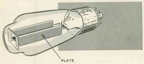
Fig. 201. When a 5U4-G is horizontally positioned, the long sides of the
plates should be vertical.
It becomes necessary, therefore, when the technician is replacing a 5U4-GB that is horizontally mounted, to obtain a tube with a structure identical to the one in the set, one whose plate and base-pin orientation correspond to that of Fig. 201. Otherwise, damage to components may occur. It is desirable to avoid horizontal positioning of the 5U4-GB when servicing a set for any considerable length of time if the positioning of the plates with respect to the pins differs from the one illustrated in Fig. 201.
In the case of indirectly heated tubes with a high transconductance, the major or long axis of the elliptically shaped control grid should be kept vertical to avoid filament-to-cathode shorts as well as microphonics.
High-current tubes, such as rectifiers, video amplifiers, audio power amplifiers and horizontal output tubes, are generally mounted vertically. Other types of mounting tend to reduce the flow of air around the tube envelope and may cause the tube's heat dissipation ratings to be exceeded, possibly damaging it. If ventilation is adequate, horizontal mounting is satisfactory but the filament pins should be in a vertical plane.
Preventing damage to low-voltage rectifier
Small current-limiting resistors (Fig. 202) are used in series with selenium rectifiers in TV sets as well as in radio receivers.
Similar but larger-value resistors are used in series with the plate of a half-wave rectifier tube in an ac-dc radio. Technicians some times jump such a resistor with wire when they find one burned out and do not have an identical unit on hand; the fact that the receiver works perfectly well without the resistor convinces them that the unit is not necessary.
A resistor of this kind serves a protective function and should always be replaced. Selenium, as well as tube rectifiers, can safely pass a certain value of peak plate current; if this current is exceeded: the rectifier may be permanently damaged.
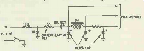
Fig. 202. Representative selenium rectifier power supply, Showing one way
in which a current-limiting resistor is inserted into the circuit.
At the beginning of the conductive portion of each cycle, when the filter capacitors begin to charge, the impedance in series with the rectifier is extremely small; the current passed by the rectifier at this time can be excessive, particularly when the line voltage is high. With a current-limiting resistor present, the peak current is reduced to a safe value.
In line with promoting longer rectifier life, avoid turning receivers on just after the set has been turned off; customers should be cautioned to the same effect. In such circumstances, a (tube) rectifier cathode is hot and ready to deliver a maximum amount of electrons; the filter capacitor has been permitted to become partly discharged, reducing the impedance in series with the iectifier. The peak current flowing under such circumstances may exceed safe limits and damage the rectifier.
Technicians not infrequently replace the rectifier tube in a TV or radio set with a different type either because the original one is in scarce supply or because they want to boost the supply voltage by using a tube capable of providing a higher dc output voltage. In many instances this is an unsafe practice. The increase in voltage, while it may substantially improve set performance, can cause the design safety margins of the receiver to be exceeded; the higher voltage produced may damage various components designed for lower-power supply potentials.
When a filament type rectifier is substituted for a cathode type, the dc voltages at the input and output of the filter choke will rise to maximum much more quickly. Since the cathode type output tubes present will require maximum current an appreciable time later, there will be a short interval just after the set has been turned on when the rectifier is operating at full output with very little or no load. The excessive voltage applied to filter, bypass and coupling capacitors in such a case can damage some of them.
When a filter capacitor has just been installed in a set, it is wise to use an old, weak (but still operative) rectifier tube to test set operation. The reason for this precaution lies in the fact that capacitors that have been on the shelf for some time will have a larger-than-normal (momentary) leakage for a short time after they are placed in use; this excessive leakage may damage the rectifier.
Use of an input filter capacitor larger than the one called for in the set's design may injure the rectifier due to the higher surge currents that are permitted to flow. Adding a small amount of resistance in series with the plate circuit of the rectifier will remove this danger. A bad rectifier tube (i.e., one with no emission) should never be replaced before the filter capacitors are tested for a short.
Plate and screen dissipation ratings
When electrons strike the plate or screen of a tube, heat is generated and power is dissipated. Every vacuum tube can tolerate a certain amount of heat; when this limit is exceeded, the tube's performance is impaired and its life shortened.
Heat is produced by the heating of the cathode as well as the plate and screen; most of the heat in a tube, however, is normally due to the flow of plate current. All of the heat must be carried away or dissipated to prevent the tube from being damaged.
Radiation, primarily through the tube envelope, as well as convection (transfer of heat by air currents) permit such dissipation to take place.
Excessive heat is generated in a tube, impairing its performance and life, if ventilation is improper. An adequate supply of air must flow past the receiver's tubes, particularly its rectifier and power output tubes. If the set owner keeps the receiver flush against the wall or covers its ventilation openings (Fig. 203) in other ways, the requisite amount of cooling is not likely to occur.
To minimize callbacks the technician should advise the set owner of the need for ventilation. Improper ventilation is particularly likely when high-current tubes are mounted horizontally in a receiver.
Holes are sometimes punched in the bottom of table-model receivers. If the set is placed on some form of soft, decorative cloth, enough of the holes can become blocked to interfere with ventilation.
The presence of a shield around a tube will raise its tempera ture very markedly. In more than one case, manufacturers have recommended that shields called for in the design of a set be discarded to prevent an injurious temperature rise.
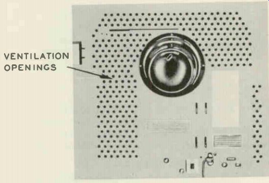
Fig. 203. Ventilation openings in the back of a TV set. Keeping the receiver
some distance away from the wall will prevent obstruction of the openings.
Undue heating of a tube enclosed by a shield may cause the tube to break. In such cases, make sure that no decrease in bias or increase in plate or screen potentials is responsible for the undue heating; then try removing the shield. If set performance suffers with the shield off, ventilation holes punched in the shield may reduce the heating sufficiently to permit the shield to be retained. Shields of this kind are commercially available.
In some instances when tubes with shields burn out too frequently and the shields can neither be removed nor adequately ventilated, the plate voltage of the tube involved may be temporarily lowered by adding a capacitor-bypassed resistor (R1 and C1 in Fig. 204) in series with the plate load. This technique has some points in its favor in areas where the line voltage is high; it will probably not work satisfactorily where the line voltage is low and is certainly not recommended in fringe areas.
The value of the resistor should be large enough to reduce the plate voltage appreciably, but not so large that the reduction adversely affects set performance. This technique has been successfully used in the case of premature 6AF4-A failures in converters in uhf-vhf television receivers.
Excessive screen dissipation will occur in a power output tube if the load is removed. Thus, an open audio output transformer primary will result in the diverting of the normal plate current flow to the screen, causing the screen to overheat and glow brightly. The tube will be damaged if power is not shut off promptly. Never operate a power output tube without a load.
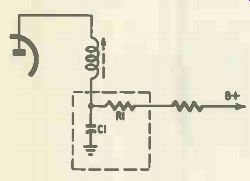
Fig. 204. How a resistor and decoupling capacitor are connected to reduce
plate voltage and excessive tube heating.
Avoiding damage to horizontal output tube
A number of conditions may cause premature failure of the horizontal output tube and should be avoided. The most frequent cause of damage to the tube lies, perhaps, in removal of its drive or input signal. Such a condition may result from the failure of the sweep oscillator due to a tube or component fault; from removal of the oscillator tube for test purposes by an inexperienced technician or any defect, in short, that eliminates or greatly reduces the signal input to the horizontal amplifier. The amplifier's (grid-leak) bias is reduced in such circumstances, permitting its plate and screen currents to rise. Furthermore, the dissipation of power is confined primarily to the tube in this case; very little power is dissipated in the load. The tell-tale sign of the trouble will be the excessive heating of the power amplifier plate; this will glow cherry-red in the absence of all drive. In some instances, where the absence of grid drive permits excessive current to flow in the horizontal output tube, the solder on the plate cap will melt, fusing the cap and plate clip together.
When an adequate size cathode resistance (about 100 or 200 ohms) is used in a horizontal output tube, the latter may be operated at three times its rated power for a period of as much as 5 minutes with little risk of its being damaged. Absence of grid drive is not as serious in tubes protected in this way as it is in the case of a tube with no cathode bias.
When a horizontal amplifier with no cathode bias must be operated for a short time to permit voltage readings to be made, insert a resistor of 100 or 200 ohms between its cathode and ground. The resistor's rating should be about 5 watts. Leads and components adjacent to the resistor should be dressed away from it to prevent the heat dissipated in the resistor from affecting them.
When a horizontal amplifier tube requires replacement every few months, instead of once a year, a number of points merit investigation. Is the horizontal drive control setting too low? To check for (as well as remedy) the condition, turn the drive control up far enough to bring overdrive bars (white vertical lines) into the picture, then reduce the drive setting to the point where they just disappear. (Decreasing the capacitance of the horizontal drive capacitor increases the drive.) Is the horizontal linearity control setting improper? In some sets, such a condition may not noticeably affect linearity and yet can cause tube damage. To check this (when likelier sources of the trouble have been eliminated), vary the linearity setting from one extreme to the other. If two points can be found where satis factory linearity can be obtained, leave the adjustment at the point where the slug protrudes farthest from the coil. Adjusting the horizontal linearity control for minimum cathode current of the horizontal output tube is often the simplest and best technique. Insert a dc millimeter in series with the cathode of the tube and turn the control for a minimum reading on the meter.
(A horizontal linearity control is generally found in older sets.) Higher-than-normal line voltages may be responsible for pre mature horizontal output tube failures. Excessive width and/or horizontal nonlinearity are associated symptoms in such a case (Fig. 205). A line-voltage check will verify whether this voltage is above normal.
A defective horizontal output transformer can cause the output tube's rating to be exceeded, damaging the tube. The output transformer should be checked to verify whether this is the case.
A flyback tester is recommended for such a check.
If a 6SN7-GTB tube is being used as a horizontal sweep oscillator, the possibility of the tube's being intermittent must be considered. If the set owner reports that the set failed to produce a raster at certain times, particularly when it was turned on just after being turned off, an erratic 6SN7-GTB may be the source of frequent horizontal amplifier tube failures. Replace the 6SN7 GTB with a 6SN7-GT, which oscillates more reliably. The 6SN7 GT is an older and discontinued type but is readily available.
When excessive failure of the horizontal output tube (or some other tube, for that matter) occurs in a series-filament setup, arcing between heater and cathode of the damper may be applying excessive voltage pulses to the filament strings.
When two horizontal output tubes are in parallel, care must be used in substituting or replacing one tube. If a single tube is replaced and the set is turned on just after being turned off one ...
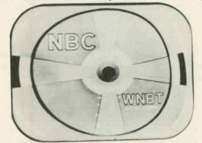
Fig. 205. Effect of horizontal nonlinearity
on test pattern. Note greater width of horizontal wedge at left, compared
to the corresponding wedge at the right.
... of the parallel tubes will be hot while the other is cold, causing an uneven distribution of current between the two. One or both of the tubes may be damaged in such a case.
It is wise to avoid operating a set with the yoke disconnected.
In some receivers, removal of the yoke removes too much of the horizontal amplifier's load; the resultant excessive screen current may damage the tube (as well as its screen voltage-dropping resistor). Cautions on high-voltage rectifiers Premature failure of the high-voltage rectifier tube may be attributed to three common causes: (1) short life due to arc-over between filament and plate; (2) failures due to arcing caused by improper lead dress; (3) premature burnouts caused by excessive filament voltage.
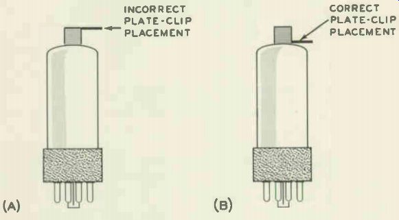
Fig. 206. In receivers where the top of the high-voltage cage is close to
the plate clip of the 1B3-GT rectifier, improper placement of the plate clip
may be the cause of corona or arcing.
The miniature 1X2 (used in older sets) is perhaps more prone to internal arc-over than other commonly used high-voltage rectifier tubes. This is so because it has a relatively small peak inverse voltage rating-approximately 15,000. During the portion of the cycle when the plate is negative with respect to the filament, the plate may start thinking it was really meant to be a cathode. If the voltage difference present between plate and filament at this time exceeds the peak inverse voltage rating of the tube, plate and filament reverse roles and a breakdown of the tube results (since current flows during both halves of the cycle, instead of only one half, causing the current capabilities of the tube to be exceeded). Replacement of the 1X2 with a 1X2-A or 1X2-B which have peak inverse voltage ratings of 18,000 and 22,000 volts, respectively, offers a solution to the problem.
Improper dress of high-voltage rectifier filament leads may cause arcs between filament wiring and chassis or filament and some other wiring, causing excessive current to flow through the tube and thus reducing its life. Avoid disturbing the existing lead dress when making tube checks or replacements, to prevent the introduction of such arcing. Be particularly careful when replacing a subminiature type high-voltage tube which necessitates a soldering and unsoldering operation. In the case of frequent high-voltage rectifier burnouts, consult the manufacturer's service notes for data regarding proper lead dress as well as other information that may prove helpful in tracking down the source of trouble.
In general, filament leads of the high-voltage rectifier should be dressed away from the horizontal output transformer proper as well as adjacent wiring and ground points. If necessary, use coil dope to keep the leads in place. Keep all high-voltage rectifier leads away from hot tubes and resistors to prevent deterioration of the leads; such deterioration may lead to arcing and premature failure of the rectifier.
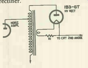
Fig. 207. Portion of high-voltage rectifier circuit, showing location of
the filament-dropping resistor (R1).
In cases where the top of the high-voltage cage is very close to the plate cap of the rectifier tube, it is possible to introduce arcing and corona by improper placement of the high-voltage anode clip (Fig. 206). In such "low-bridge" cases, make sure the placement of the clip puts the maximum distance between the grounded cage top and the wire leading to the clip.
When frequent rectifier burnouts occur, check the set for evidence of arcing after the rectifier has been replaced. Replacement of the filament leads, as well as any protective tubing used over them, is recommended when arcing between these leads and other wiring or ground has taken place.
Excessive filament voltage of the high-voltage rectifier is rather difficult to detect since it cannot be measured directly. The voltage across the filament is usually 1.25, but the voltage between either filament pin and chassis is measured in kilovolts. Check the value of the resistor in series with the filament (see R1 in Fig. 207) when frequent rectifier burnout is the complaint. If the resistor has decreased as much as 1 ohm in value (compared to the value specified in the set schematic) replace it with a unit of the correct resistance.
When the Iine voltage is high in the set owner's location and frequent rectifier burnouts occur, the series-filament resistor can be increased in value to reduce the excessive filament voltage that is probably present. If the filament voltage is reduced too much, of course, the high voltage will be lowered to a level where good set performance is not obtained.
If no filament resistor is present, try inserting a 1.2-ohm 1/2 -watt resistor in series with the high-voltage rectifier filament. Connect one side of the resistor to the filament socket contact point, the other end to an unused socket contact. Keep the resistor pigtails ...
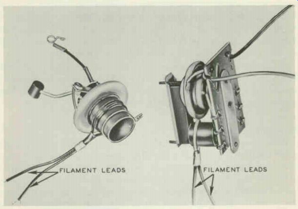
Fig. 208. Photos of fly back units, showing number and position of filament
windings. One or two turns, may be used, depending on the filament voltage
requirements and the construction of the flyback transformer.
... short and avoid sharp points on both the wire and the soldered connections to prevent corona. The resistor should be dressed close to the socket.
A shift in the coupling of the high-voltage rectifier filament winding on the flyback transformer may be the source of frequent tube burnouts (Fig. 208). If a similar flyback is present in another receiver, a comparison can be made to verify whether such a shift has occurred. If it has, the filament winding may be moved a short distance-perhaps 3/16 inch or thereabouts-away from the high-voltage winding on the transformer. If set performance remains satisfactory, the winding may be left in this position.
Insufficient as well as excessive filament voltage may reduce the life of the high-voltage rectifier. When premature rectifier burnouts are associated with symptoms that indicate the presence of reduced high voltage and no other. trouble can be found, the series filament resistor should (if present) be reduced to perhaps half its value. (Shunt the resistor with one of equal value.) This kind of trouble occurs particularly in low-line-voltage locations.
Caution must be observed in the choice of a 1B3-GT as a replacement. All 1B3-GT's, with the exception of some early make G-E tubes, have a "floating" or unconnected No. 5 pin. In the G-E tubes referred to, pins 5 and 7 are internally connected.
Since the filament voltage-dropping resistor often used in high voltage rectifier circuits may be connected between pins 5 and 7 on the socket, use of one of these early-make G-E tubes may short the filament resistor and increase the filament voltage applied to the rectifier, thus reducing the latter's life.
To avoid such developments, check for continuity between pins 5 and 7 if a possibly early-make G-E tube is to be used as a replacement. If continuity is read, clip pin 5 off at the base before using the tube as a replacement.
Protecting C-R tubes
Before replacing a defective picture tube, make sure that the conditions which damaged the first tube are not present; they may injure the replacement as well. Be particularly careful to check the dc voltage between cathode and filament of the picture tube. Presence of an excessive voltage between these two elements can produce arcing between them. The heat produced by the arcing may either cause the heater to burn out or to short to the cathode. The manufacturer's service data will indicate the correct heater-to-cathode (or heater-to-ground, and cathode-to-ground) voltage. Arcing is most likely to occur where a tube with an abnormally low heater-to-cathode breakdown potential is used.
(When a set schematic is unavailable, data regarding a C-R tube's maximum permissible heater-to-cathode voltage may be found in a tube manual.) When the tube filaments are connected into a series-filament hookup and the heater is found open, the schematic of the set should be studied with care and efforts made to determine whether a short in any tube, or some other component defect, could have resulted in the blowing of the C-R tube's filament.
A mechanical source of danger to the picture tube in some sets is the back panel of the receiver. If care is not used in the removal of this panel, it may fall on the neck of the tube, damaging or breaking it.
Tube damage due to grid emission . When a vacuum tube is evacuated during manufacture, a small amount of cathode-emitting material is sometimes unintentionally splashed onto the grid. The grid can, in consequence, emit electrons (like a cathode) if it should become hot enough during operation. Since the spacing between grid and cathode in a number of tubes is very small, excessive heater voltage or cathode current can cause enough heat to be generated and transferred from cathode to grid to cause grid emission. A positive voltage is produced between grid and ground as a result of such emission, lowering the bias. The reduced bias tends to cause increased cathode current and greater heating of the grid, promoting a greater degree of grid emission. This cumulative effect may quickly destroy the tube in some cases. In other instances, considerable damage to other tubes and components may occur due to the large current generated. The tube affected could lose all its emission; a rectifier tube through which a large current flows, due to the positive biasing of the grid-emitting tube, may suffer a loss in emission; plate and screen resistors may burn out, etc.
The larger the grid-to-ground resistance present in the tube affected, the more severe the grid-emission effect will be.
In a power output tube, the relatively large amount of heat generated during normal operation is particularly likely to pro mote grid emission. The heavy current produced when grid emission occurs tends to cause liberation of gases from over heated elements. The consequent bombardment of the cathode by the positive ions of gas may destroy the cathode.
Since grid emission is promoted by the presence of an excessive grid-to-ground resistance (such excessive resistance increases the positive voltage produced between grid and ground and thus steps up the rate at which the bias progressively becomes more positive), it is wise to check the grid resistance of any tube which seems to have suffered a premature failure of emission. When the normal value of a grid resistor is in excess of 100,000 ohms, such a check is particularly suitable. Replace any resistors which are substantially above their correct value.
Excessive heating of a tube may also be the cause of grid emission. Make sure that proper ventilation is not impeded by the flush positioning of a receiver against a wall, obstruction of vent holes, etc. To determine whether grid emission is present in a tube, check its grid-to-ground voltage. If this voltage is positive or insufficiently negative with the tube in its socket and zero or adequately negative with the tube out, grid emission is probably present. Another way to check is to disconnect the coupling to the tube (leaving the tube in the circuit). If an originally positive or insufficiently negative grid-to-ground voltage is still present, grid emission in the tube is probably responsible. Grid emission...
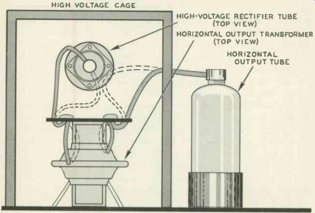
Fig. 209. Proper and improper lead dress in the high-voltage cage. Dotted
lines indicate incorrect positioning of leads; high-voltage wires are too
close to each other.
... generally takes some time to develop. A final voltage test for it should therefore be delayed until the tube has been permitted to heat for an hour or more.
Premature tube failure due to leaky coupling capacitor A positive grid-to-ground voltage produced by a leaky coupling capacitor not infrequently burns out the tube whose bias has been reduced. A test for this kind of trouble should be made when recurring burnouts (of tube cathodes) are a problem.
Miscellaneous sources of arc-caused damage to tube and components Some sources of damage to tubes and components due to arcing have already been discussed. Such arcing may be unintentionally introduced by the disturbance or improper placement of lead dress after a tube replacement in the high-voltage section (Fig. 209). If the lead to the horizontal amplifier plate cap is incorrectly oriented and lies too close to a wall of the high-voltage cage, a severe undetected corona may cause the output tube to fail within several weeks. The presence of a shiny little circle on the section of the cage opposite the cap will indicate that corona has been (or still is) taking place. Improper dress of the high-voltage rectifier's filament leads may result in arcing that ruins the flyback transformer. Sometimes arcing between the high-voltage rectifier plate cap and the damper tube will occur if the two are in too close proximity, causing destruction of the damper tube. In cases where the damper is a 6W4-GT, substitution of a 6W4-GT with a shorter-sized envelope may minimize the possibility of such arcing.
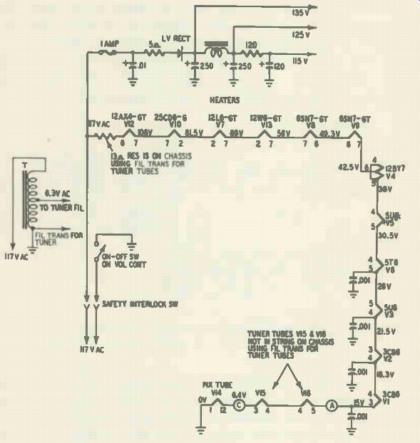
Fig. 210. Series-filament circuit employing only a single string of tubes.
Series-filament circuits
There are a number of facts about series-filament circuits (Figs. 210, 211) that the technician should know to minimize the possibility of damage in servicing tubes connected in this way.
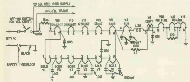
Fig. 211. Series-filament circuit in which two strings of tubes are in parallel.
The two parallel strings are in series with a third group of filaments A primary
caution: never remove a tube from a series-filament string while the receiver
is in operation. In the first place, the filaments of other tubes in series
with the absentee will often be open-circuited with respect to their source
of voltage, rendering the receiver inoperative or improperly operative, thus
making whatever test was intended valueless. More important, excessive filament
voltage may (in some types of filament circuit) be imposed on one or more
tubes, possibly damaging them. The possibility of failure of tubes for other
reasons is increased as well. If a resistor (R) is in shunt with the tube
that has been re moved (Fig. 212), the resistor will overheat since an excessive
voltage will now be present across it; in a few seconds, it may be permanently
damaged.
For similar reasons, switching on a series-filament set from which one or more tubes are absent may prove very detrimental to one or more tubes and should be avoided. Set owners should be cautioned not to leave a set of this type on when it has developed trouble, to avoid increasing the extent of the damage present.
When a tube is replaced in a series-filament receiver, a check of the schematic or the set itself is advisable to determine whether a resistor is present across the tube filament. If there is, the resistor should be checked for an open circuit. If the tube is replaced without a test being made (and an open resistor is present across the filament) the tube filament will probably burn out.
It is recommended that no defective tube be replaced before the schematic is studied and consideration given to the possibility that a defect in some other tube could have blown the first one out. Here are some of the ways in which a defect in one tube can cause damage to others: A heater-to-cathode short in one tube can, by bypassing ac voltage from several others, increase the filament voltages on the remaining tubes in the string, injuring one or more of them.
Failure of the filament in a tube which is in a series with the damper will cause the damper to become inoperative. The con sequent removal of plate voltage from the horizontal output tube in many receivers will increase the screen current in this tube, tending to damage it, unless its filament voltage has been removed by the first-mentioned defect.
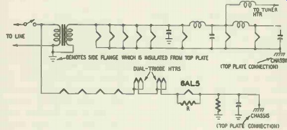
Fig. 212. Series-filament circuit in which a shunt resistor R is used across
one of the tube filaments (6AL5).
The horizontal output tube may also be damaged if a tube filament open-circuits in the series string in which the horizontal oscillator filament is positioned. Drive (input signal) to the horizontal output tube is removed in such a case, and its plate dissipation may thus become excessive, damaging the tube. (It is assumed that the horizontal output tube is in a string separate from that of the horizontal oscillator and remains operative.) The technician should become familiar with the characteristic glow of filaments used in series-filament circuits. That is, he should become familiar with the normal color of correctly lit filaments in various glass-envelope tubes. This knowledge will enable him to spot more readily excessive or inadequate filament lighting, when such a condition develops.
One cause of excessive or inadequate filament voltage is a change in the value of a filament voltage-dropping resistor. The resistors used in TV sets are generally special temperature sensitive units with a very low "hot" resistance and a high "cold" one. The function of such a resistor is to eliminate or minimize the filament surge voltages that occur when the receiver is first turned on. Such surges are damaging to the tube filaments.
For maximum accuracy, a temperature-sensitive resistor should be tested indirectly by measuring the voltage drop across it or the filament voltages of the tubes in series with it. When a unit of this type is found defective, obtain an identical replacement.
The life of tubes in series-filament circuits is inevitably less than that of tubes whose filaments are connected in straight parallel arrangements, due to the greater stresses imposed on the series-filament tubes. Some tubes are designed with a 450- or 600-milliampere heater having a controlled warmup time. Such tubes require exact replacements.
Cautions on use of tube testers
When a tube is being tested in an emission type tester, the possibility of its being damaged by improper use of the tester must not be overlooked. In an emission test made in this type of tube checker, no grid control is present and nearly all of the electrons emitted from the cathode of the tube under test flow to the plate. This imposes a very heavy load on the cathode, comparable to the loading on a rectifier tube when a shorted filter is present. To avoid damage to the tube being checked, make the emission test as brief as possible-limit it to the time needed for the meter needle to reach the end of its swing. Leaving the emission button depressed for a longer time exposes the tube cathode (or filament cathode) to swift destruction, particularly when a battery-portable type tube is being tested.
Miniature tubes in which the spacing between elements is extremely close (the 6AK5, for instance) should not be subjected to a short test in a tube tester. During such a test, voltages are applied to the elements being checked; the resultant electrostatic attraction set up between the narrowly spaced elements tends to cause them to short-circuit. Use an ohmmeter to test for a short in such tubes or else try tube substitution.