TUBE trouble can cause the raster to be missing, intermittent or slow in developing. Possible symptoms may be grouped as follows: (1) raster and sound both absent; (2) raster absent, sound normal; (3) raster absent, hum in sound; (4) intermittent raster; (5) excessive warmup time.
Localizing defective tube when raster and sound are absent
When both raster and sound are absent and the receiver's tubes light, the likeliest source of trouble is the low-voltage rectifier. Replace this tube (after first checking for a shorted filter) and note results. The same procedure is used when all glass tubes except the low-voltage rectifier are seen to light.
When a selenium rectifier is present, voltage, resistance and substitution tests will reveal whether a defect in this unit is killing raster and sound.
A shorted rectifier can kill both raster and sound by eliminating or greatly reducing B-supply voltages. This possibility can be checked by measuring the B-supply voltage. A fast check of the B voltage may be made, without removing the chassis from its cabinet, with the aid of a socket test adapter (Fig. 301). This unit makes under-chassis socket contacts available above the chassis.
If an adapter of this type is not at hand, withdraw one of the receiver tubes and measure the voltage between its plate or screen socket contact to ground. Make sure before trying this test that (1) the receiver does not have a series-filament hookup and (2) removing the tube is not likely to cause overloading of other tubes or components. A good tube to remove for this test is a video if amplifier since its drain is relatively low and its removal is not, in most cases, likely to cause damage. In any case, make the voltage measurement as quickly as possible, then replace the tube.
When determining into which socket contact to insert the "hot" voltmeter lead, keep in mind that the reckoning is counterclock wise from the top of the socket.
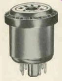
Fig. 301. Test adapter for making above-chassis voltage checks. Adapters
for seven- and nine-pin miniature tubes are commercially available.
An alternate way to make a B-voltage check is to remove the video if tube, connect the exposed end of an insulated piece of wire to its plate or screen pin, then reinsert the tube into it socket. A top-chassis check of the plate or screen voltage can be made by measuring between the exposed open end of the wire and chassis (or B minus). Be careful not to short the exposed end of the wire to chassis.
If it is found that the B voltage is very low or absent, a top chassis resistance measurement may be taken from the rectifier filament. (It is assumed that a home service call is being made and that the technician wants to remedy any tube fault right there.) If a short reading is obtained, remove the various tubes in the set one at a time, leaving the ohmmeter connected between the rectifier filament and ground. When removal of one particular tube eliminates the short, that tube is defective.
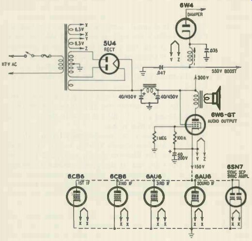
Fig. 302. Part of stacked-tube circuitry.
If the B voltage is low, no short readings are obtained, ac plate voltages on the rectifier are ok (as determined by a top-chassis voltage check) and replacement of the rectifier tube does not cure the trouble, try withdrawing tubes one at a time while monitoring the plate or screen voltage at the socket of a video if tube. (This test is not, of course, to be made on a series-filament receiver.) The tubes should be lifted out of their sockets and kept only a short distance away to facilitate quick reinsertion. Don't leave any tube--particularly the horizontal oscillator--out of its socket for more than an instant to prevent damage to tubes or components. When withdrawal of any tube returns the B voltage to normal, that tube is probably shorted and a new one should be tried in its place.
Sometimes two tubes rather than one are shorted. Double trouble of this kind will generally require bench tests to locate.
In the case of a stacked tube circuit, such as the one shown in Fig. 302, a cathode-to-heater short in the damper will eliminate both raster and sound. Such a short reduces the B boost voltage to the level of the 150-volt supply, causing the damper cathode and plate to be at the same potential. By thus eliminating conduction in this tube, the damper is effectively open-circuited. The plate of the 6W6-GT audio output tube, normally fed from the B boost voltage, receives a supply voltage of only 150 as a result of the cathode-to-heater short in the damper. This brings the plate and cathode voltages of the 6W6-GT to the same level and thus stops conduction in this tube as well.
Try a new damper tube in a receiver of this type when both raster and sound are absent. In other receivers, of course, a new damper is normally substituted only if the raster alone is absent.
In a series-filament receiver, the open-circuiting of any tube filament that happens to be in series with both a horizontal circuit and sound tube will kill both raster and sound.
Raster absent, sound normal When sound is normal but the raster is missing, the following procedures may be used to localize any tube trouble present.
Note whether any horizontal sweep circuit tube, the high-voltage rectifier or the cathode-ray tube is unlit. (In the case of the high-voltage rectifier, it may not always be possible to determine by inspection if the filament is lit or not since the filament's voltage is only 1.25 or thereabouts and its lighting is barely visible in the best of circumstances.) Replace any unlit tube and note results.
In the case of a series-parallel filament setup when one or more tubes are seen to be unlit, determine (by inspection of the set schematic) in what string an unlit tube is present, then resistance check the tube filaments in that string.
If the picture tube is unlit, the trouble may lie in either the tube filament or the filament supply voltage source. To localize the trouble further test the filament supply voltage at the socket of the tube with the tube out. If the proper filament voltage is present, a defect in the picture tube filament is indicated. Some times loose filament connections in the base prongs are the source of the trouble; resoldering them is a good way to test for, as well as correct, such a fault.
When filament voltage is absent, a short in some tube other than the cathode-ray tube may be responsible (Fig. 303). In certain TV sets, the filament of the picture tube is in parallel with that of the damper. A short in either tube may eliminate filament voltage in both. Try a new damper, in sets of this kind, when the picture-tube filament does not light. In the case of series-filament receivers, trouble in any tube filament in series with that of the picture tube can eliminate its filament lighting; check for the presence of such a defect when receivers of this kind are being worked on.
When the receiver's tube filaments are seen to light normally, check the high voltage present at the C-R tube anode with a high voltage probe and voltmeter or-if no fancier and safer test can be made-by holding the anode connector close to the receptacle on the tube and noting whether a spark is obtained. (Sparking the connector io chassis is not recommended even though many technicians resort to this procedure. It is possible to blow the high-voltage fuse-if one is present-or damage components in the high-voltage circuits when a fuse is absent.) Some experience is necessary to determine whether the strength of the spark indicates an adequate amount of high voltage.
If a normal spark is obtained at the anode and no raster is present, the ion magnet may be improperly set or defective, the tube's bias may be excessive or the tube may be defective.
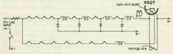
Fig. 303. Filament circuit of a typical TV chassis. A filament-cathode short
in the 6.SQ7 can shunt the filament current to ground before it passes through
the picture tube, causing the cathode-ray tube to remain unlit.
The first check that seems logical is a test of the ion magnet.
When readjustment of this unit (preferably in a darkened room) is ineffective in producing a raster, a dc voltage check between the picture-tube control grid and cathode is the next logical procedure. (Make sure to keep the brightness setting low after the ion-magnet adjustment has been checked since the magnet may not have been returned to its proper setting. Damage to the tube can result if the brightness setting is high and the ion-magnet setting is incorrect.) If the grid-to-cathode voltage cannot be reduced to zero or to a few volts negative by manipulation of the brightness control, but remains excessively negative at all times, a defective tube may be the cause of the trouble in some cases. In a receiver in which direct coupling between the video amplifier and picture tube is used (Fig. 304), a defective video amplifier may cause an excessive picture-tube bias to be developed, blanking out the raster. Try replacing the video amplifier to check on this source of trouble.
A strong negative bias may indicate overloading due to excessive signal input. Try switching to an unused channel to check on this possibility. If the raster reappears, overloading of this kind is definitely indicated. A defective agc tube (or circuit) may be the cause of the symptoms. Substitution of a new agc tube will determine whether the original one is defective.
If the picture-tube bias is normal, the ion magnet has been absolved of blame and the high voltage applied to the tube seems OK, loss of emission is generally indicated. Use of a C-R tube checker will quickly determine whether the tube is defective in emission. When a C-R-tube tester is not available, the tube will have to be tested by the more laborious process of substitution of a known good tube or the use of a universal picture tube. (See the last page of Section 7.) A corroded or poor contact in the picture-tube anode connection may be responsible for the loss of the raster. To check on this possibility, run a length of high-voltage wire from the anode receptacle to the old anode connector. Attach the end of the wire (or new connector) firmly to the old connector. If a wire is used, it will have to be held in position to keep it from falling out of the receptacle. If the raster is restored by this setup, the old anode connector should be repaired or replaced.
If no satisfactory spark was obtained at the anode connection of the picture tube, the metallic edge of an insulated screwdriver should be brought near the plate clip of the high-voltage rectifier.
If an arc is seen to jump across to the screwdriver blade, normal operation of all tubes up to, but not including, the high-voltage rectifier, is indicated and substitution of a new rectifier called for.
If no spark or a very weak spark is noted, in this test, remove the plate clip to the rectifier and see whether bringing the screwdriver near the disconnected clip will now cause an arc to be drawn (make sure the clip is not permitted to touch ground). If an arc is drawn, a shorted high-voltage rectifier tube may be present.
If no or little high voltage is present at the picture-tube anode and little or no spark is noted at the plate clip of the high-voltage rectifier, test for a purple (ac) spark at the plate cap of the horizontal amplifier. Presence of such a spark here and its absence at the plate of the high-voltage rectifier indicate a circuit defect between the two points. If little or no spark or only a blue dc spark is noted at the plate cap of the horizontal amplifier, check the horizontal oscillator and amplifier tubes by substitution.
It is preferable to replace the horizontal oscillator and amplifier tubes at the same time rather than in succession. This is so because a bad horizontal oscillator tube may have caused the horizontal output tube to become defective as well. If a new oscillator is substituted and the output tube is dead, the service technician may temporarily arrive at the false conclusion that the oscillator is not defective since its replacement did not restore receiver operation to normal.
Next, the damper tube, as well as any other tubes present in the horizontal circuits, may be successively checked by substitution, and results noted. A defective afc tube may, in some in stances, make the horizontal oscillator tube inoperative and kill the high voltage; a substitution test of this tube is therefore suggested, along with the other tube substitutions, when a no-raster condition is being serviced.
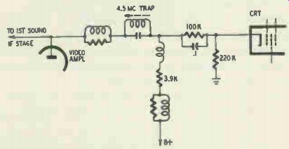
Fig. 304. Direct coupling between video amplifier and cathode-ray tube. Loss
of emission in the video amplifier will increase the cathode voltage of the
tube, possibly increasing its bias to cutoff in some cases.
If an insulated plate cap is present on the horizontal output tube, the spark test previously described cannot readily be made.
In such a case, listen for the characteristic high-pitched sound generated by the horizontal sweep signal. This whistling sound may be more readily detected if its pitch is changed by varying the horizontal hold control. Presence of this characteristic sound indicates that all tubes and components as far as the plate winding of the horizontal amplifier are operating; it also eliminates the possibility of a short in the high-voltage rectifier tube.
The presence of visible arcing will eliminate the need for the sequence of tests just described. Such arcing can, by eliminating the high voltage, cause the raster to disappear.
Raster absent, hum in sound
In some receivers using a filament circuit setup such as the one shown in Fig. 303, a cathode-to-heater short in the first audio tube will eliminate filament voltage from the picture tube and kill the raster. The short will also eliminate the sound signal, leaving only a hum audible. If, in sets of this type, raster and desired sound are missing, hum is audible and the picture tube is unlit, try another first audio tube.
Intermittent raster
An intermittently disappearing raster, with sound normal, is often produced by dirt on the picture tube prongs, a loose connection at one of its pins or a defective socket contact.
Oxidized contacts in the picture-tube socket are often the cause of intermittent filament lighting. To test for such trouble, remove the tube, insert ac voltmeter test leads into the filament socket contacts from above the socket, then tap the socket from various angles. Make sure the tapping does not interrupt the contact of the test leads with the socket. If the filament-voltage reading varies or becomes intermittent, a socket replacement is called for. Repair of a socket is often ineffectual and is not recommended.
Loose connections in the filament prongs of a high-voltage rectifier tube may be the cause of an intermittent raster. Resoldering these pins will test for, as well as eliminate, this possible source of trouble. Such a resoldering job is especially recommended when the soldering at the prong end looks poor.
Disappearance of the raster after the receiver has been on an hour or so may be due to an air leak in a high-voltage rectifier tube. The glass in such tubes can deteriorate, partly because the high peak inverse voltage that develops between cathode and plate subjects the glass to bombardment by high-velocity electrons. If a tube envelope has suffered such disintegration, air can leak into the tube, killing the high voltage. The amount of air leakage is very small and may be effective only when the tube has reached full operating temperature. To test for such a defect when the complaint is a raster that disappears after an hour or so of set operation, replace the high-voltage rectifier tube and note results.
Excessive warmup time
TV receiver warmup time, or the time it takes for satisfactory picture and sound to be received, is generally 30 seconds or less.
In some cases, it takes considerably longer for raster and picture to develop. Possible sources of such trouble may be:
1. Reduced emission in the low-voltage rectifier. This is especially likely if the sound is slow in reaching its maximum volume.
2. Slow-heating horizontal output tube. 6BQ6-GT (6BQ6-GTB/ 6CU6) type tubes in particular are likely to have heaters that take an undue length of time to become fully warmed.
3. Defective damper tube. Sometimes slow-heating damper and horizontal output tubes are jointly responsible for the symptoms present. To detect such double trouble, time the warmup interval before and after replacing one tube. If the time has decreased but is still excessive when one of these tubes has been replaced, try replacing the other. Other pairs of tubes may (among the ones listed) also act as double sources of delayed warmup and should be checked along similar lines.
4. Poor connection between the internal plate lead and plate cap of the horizontal output tube. Reheating the cap with a soldering iron will test for, as well as correct, this kind of trouble. A successful repair of this type will save the cost of a tube replacement.
5. Defect in the C-R tube. In such instances, not only will the raster take a long time to appear-the picture contrast may not become maximum for some time as well. The picture in a set having slow heaters usually has a silvery, three-dimensional appearance.
Fig. 305. Photo of test pattern indicates insufficient width.
Size, linearity and brightness troubles
Size, linearity and brightness troubles probably make up the most common group of TV defects. They may be arranged, on the basis of symptoms, into these categories: (1) insufficient width; (2) vertical deflection absent; (3) insufficient height; (4) vertical shrinking or gradual decrease in height; (5) vertical nonlinearity; (6) horizontal nonlinearity; (7) insufficient brightness; (8) excessive brightness.
Insufficient width due to tube troubles
Insufficient width (Fig. 305) may be due to a weak damper, horizontal output tube or low-voltage rectifier. When the rectifier is weak, other symptoms will generally (but not always) be manifest, such as reduced height, lessened contrast, etc. Reduced width may also be produced by lowered emission in a horizontal oscillator tube. A reduction in high voltage will generally be associated with the reduction in width produced by defects in horizontal circuit and low-voltage rectifier tubes; such a loss in high voltage may, however, be too small to produce noticeable symptoms be cause of the reserves of brightness available.
In series-filament receivers, any defect that tends to reduce the filament voltage of a horizontal circuit tube may reduce the width.
Cathode-to-heater leakage in a tube or a defective ballast tube (when one is used in the set) are examples of defects that may reduce width by decreasing filament voltage on one or more tubes.
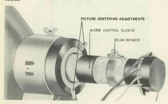
Fig. 306. Sleeve made of brass or aluminum can be used as a width control.
Certain makes of tube, particularly types used as horizontal amplifiers, may not perform as well as others. If the efficiency of the circuit is somewhat below normal and the line voltage avail able is also below normal, replacement of an old tube with an inferior-make new one may not result in satisfactory width. Try several makes of tube under such circumstances.
Where reduced line voltage is responsible for insufficient width, it may be possible to replace the low-voltage rectifier present with a more efficient one; for instance, a 5V4-G may be used to replace a 5Y3-GT. The service technician must make sure, however, that the increased supply voltages will not damage various components.
Before making such a substitution, it is best to check with the set manufacturer or his local distributor's service department.
A rather peculiar and hard-to-find source of insufficient width may develop in receivers where the B boost voltage is used to feed the vertical as well as the horizontal amplifier. The trouble refer red to is a defective vertical amplifier tube. The defect (grid emission or excessive gas) produces an excessive flow of plate current in the vertical amplifier and thus imposes a very high drain on the B boost line. The boost voltage is lowered in consequence, reducing width but not necessarily height. Enough reserve height is present in most sets to make a relatively slight reduction in vertical amplifier output unnoticeable; the same reduction in efficiency may, however, have a marked effect on width.
Fig. 307. Photo shows insufficient height.
In some receivers a brass or aluminum sleeve is used on the picture-tube neck for adjusting width (Fig. 306). Improper setting of this sleeve may be responsible for a slight loss in width.
Vertical deflection absent
When a horizontal line alone is seen on the picture tube, the usual cause of the trouble is a faulty vertical oscillator or amplifier tube. (It is assumed vertical height and linearity adjustments are correct.)
Insufficient height
When insufficient height is the complaint (Fig. 307) either the vertical oscillator or vertical amplifier tube may be responsible.
If height and vertical linearity adjustments do not restore the height to normal, replace these tubes. If replacement one at a time does not eliminate symptoms, try replacing both tubes simultaneously, since both may be defective. The vertical amplifier is more likely to be the source of insufficient height than the vertical oscillator and should be replaced first. An intermittent collapse or reduction of vertical size will sometimes occur in sets using a double-triode tube as a joint vertical oscillator and amplifier.
Vertical shrinking
A creeping or gradual loss of vertical size sometimes occurs in television receivers. The size loss may total approximately 1/2 to 1 1/2 inches and the time taken for maximum shrinkage to occur may be 1 to 3 hours. The source of such trouble often lies in a weak vertical oscillator or amplifier, a weak low-voltage rectifier or a weak horizontal output or damper tube (in cases where the vertical amplifier is fed from the B boost line). When a decrease in line voltage is responsible for the shrinking, use of a more efficient vertical output tube may eliminate the symptoms.
Increasing height by tube substitution
Where an "extra ounce" of height is needed or when adequate height without foldover cannot be obtained, it may be possible to achieve a quick remedy by a judicious tube substitution when a home service call is being made and the customer is not willing to stand the expense of a shop repair.
A 6K6-GT may be replaced by a 6W6-GT, 6V6-GT or 6Y6-G, a 6BL7-GT by a 6SN7-GTB, and a 12BH7-A by a 12AU7. Since the new tube will often draw a larger filament current, such substitutions are not feasible when (1) the tube to be replaced lies in a series-filament circuit or (2) the power transformer will not take the increased filament drain.
To test the power transformer's capabilities, operate the set for 5 minutes or more first with the old tube in the circuit and then with the new one, feeling the transformer in each case. If the transformer runs much warmer with the new tube don't make the substitution. Another way to check on the feasibility of the substitution is to ask the set manufacturer or one of his distributors about the transformer's ability to handle the increased current.
When both height and width are inadequate (Fig. 308) and height and width adjustments do not restore raster size to normal, try a new low-voltage rectifier. Such a substitution is particularly indicated if there is an accompanying reduction in sound volume or insufficient contrast or if the focus control achieves or approaches proper focus only at one end of its range.
A defective damper or horizontal or vertical output tube may reduce both height and width in receivers where the vertical amplifier is fed from the B boost line.
Vertical nonlinearity
Before troubleshooting sources of vertical nonlinearity, the technician must sometimes make sure that it is actually present.
When a test pattern is not being transmitted (which is most of the time) and some uncertainty exists whether vertical nonlinearity is present, a fast check may be made as follows: Move the vertical hold control to a setting at which the picture moves slowly downward. Now observe the width or thickness of the vertical blanking bar (Fig. 309). This is the thick, black horizontal bar that normally appears at the bottom of the picture, where it is largely out of sight under ordinary conditions. Note whether the thickness of the bar changes as it moves down the face of the tube. If it does, vertical linearity is imperfect.
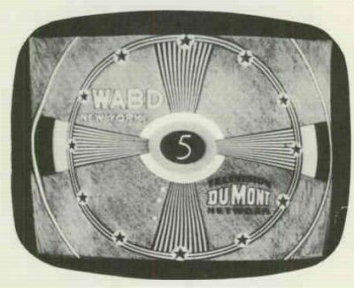
Fig. 308. The test pattern is pulled in. The photo shows inadequate width
and height.
Vertical linearity is obviously improper when a horizontal bar appears at the top or bottom of the raster and picture. This bar is a horizontal strip that appears brighter than the rest of the raster when the latter is inspected with the contrast setting reduced to zero. The condition is often characterized as vertical foldover. While this label is not really accurate, its use is wide spread. The likeliest tube sources of the trouble are the vertical oscillator and amplifier. A weak low-voltage rectifier may also be the cause of vertical nonlinearity.
When the line voltage rises above or drops below its normal level, vertical foldover may appear in some cases. Replacement of the vertical output tube is suggested to clear up such a condition. The efficiency of the vertical output tube is often critical in the presence of line-voltage changes. Since considerable variation is present in the tubes made by different manufacturers, several makes of tube may have to be tried before a satisfactory one--i.e., one that will provide adequate height without foldover in the ...
Fig. 309. The vertical blanking bar can be examined by adjustment of the
vertical-hold control.
... presence of above- or below-normal line voltage-is found. Vertical foldover may sometimes be traced to reduced emission in the horizontal output or damper tube in receivers where the vertical amplifier is fed from the B boost line.
Horizontal nonlinearity
When the picture is not properly proportioned in the horizontal direction, horizontal nonlinearity is indicated. One or more vertical white lines are often associated with such nonlinearity. Width and/or brightness may be below normal.
Possible tube sources of such trouble include the horizontal amplifier, damper, horizontal oscillator and discharge tubes. These should be tested by substitution (after horizontal drive, width and linearity adjustments have been tried). Other symptoms of horizontal nonlinearity include horizontal stretching of picture elements and/or excessive brightness at the left side of the picture, possibly caused by a defective horizontal output, damper or low-voltage rectifier and wrinkles at the left side of the picture (frequently caused by a defective damper). Poor horizontal nonlinearity may, in some instances, be due to an improper setting of the ion magnet. Check this by readjustment of the magnet when likelier sources of the trouble have been eliminated.
Insufficient brightness
The most common cause of insufficient brightness (assuming that the horizontal drive setting is correct) is, perhaps, a reduction in emission of the high-voltage rectifier. Replace the tube to test for this source of trouble. Such a replacement is particularly war ranted if the picture size increases greatly while its brightness goes down when the brightness setting is advanced. This condition--blooming--may also be noted when the contrast setting is increased. The damper and horizontal output tubes (as well as the high-voltage rectifier) are possible sources of such trouble.
In some cases, a gassy vertical output tube which is fed from the B boost line will cause reduced brightness by causing the B boost voltage to be lowered (due to the heavy drain imposed on the line by the gassy tube). A loss of emission in any tube in the horizontal sweep circuits may be the cause of insufficient brightness. So can a low-voltage rectifier whose emission has dropped.
Improper setting of the ion magnet may be responsible for reduced brightness. Or the magnet may be defective. Sometimes the magnet's effectiveness is reduced by the presence of metal filings on it; such filings effectively short-circuit the magnetic field. Remove the metal particles with a magnetized screwdriver to correct this kind of trouble.
In some sets using a picture-tube accessory known as a magnetic shield ring, brilliance will be reduced if this ring moves too close to the ion magnet (and thus shunts it). A shield of this kind should be approximately 3/4 inch away from the ion magnet.
A relatively slight loss in brightness may be due to a dirty picture-tube face. Inspection will reveal this source of trouble. Clean the surface with a soft, damp cloth (use a soapy cloth if consider able dirt is present), then dry it. The safety glass may also be cleaned at this time.
Arcing or corona in the high-voltage section may be the cause of poor brightness. Such arcing will almost always be audible even if it isn't visible; listen for it in a silent room.
Unsuspected arcing at the picture-tube anode connection may lead to an incorrect condemnation of the tube as the cause of low brightness. Remove the rubber at the anode connector to deter mine if arcing exists. If arcing is neither visible nor audible, any remaining suspicions regarding its presence may be checked by connecting a piece of high-voltage wire between the anode receptacle and the connector and noting whether the symptoms now disappear.
An accumulation of dirt around the anode receptacle may be causing corona here, reducing the high voltage and the bright ness. If such corona is noted, wash the area around the receptacle gently but thoroughly with scouring powder, then dry it; this should eliminate the corona.
Corrosion in the plate clip of a horizontal amplifier tube may be the cause of reduced brightness. Check for such a defect by inspecting the clip; remedy it by removing the corrosion layer.
When no other source of insufficient brightness can be found--that is, when the high voltage at the anode connector seems normal, the tube's bias and other element voltages are normal and the ion magnet has been eliminated as a possible source of the trouble, the tube itself is probably faulty. A defective C-R tube is particularly indicated when a blue haze is seen in it.
Don't try a new picture tube without first inspecting the prongs of the old one and resoldering any that look in the least suspicious.
Even if they don't look suspicious, it is worth while to resolder those going to tube elements; then recheck the brilliance. The cost of a new picture tube may, be saved by such a procedure.
In some G-E sets using half of a double triode for vertical blanking, low picture brilliance accompanied by retrace lines in the picture at normal brightness settings can be due to a defect in this tube section.
Excessive brightness
When the raster brightness is excessive and the brightness control is unable to reduce it to zero, check the picture tube's cathode voltage. If this reading can be made to reach 60 to 100 volts positive with respect to the control grid (with the picture tube disconnected), then the tube is defective.