IN every television receiver, without exception, picture and sound travel through identical paths in the front end, and in most receivers through a larger number of circuits. Since the sound takeoff is generally somewhere between the output of the video detector and the input to the picture tube, it isn't surprising that sound and picture troubles are often found together.
A knowledge of TV circuitry helps pinpoint troubles. Thus, if both sound and picture are defective or missing, the difficulty lies in a circuit handling both sound and picture. On the other hand, if sound is defective or missing but the picture is good, then trouble exists in a circuit that handles audio alone. Similarly, if the sound is good but the picture is defective, then the service technician should look at circuits handling video alone. This isn't a strict rule since there can be, and there are, exceptions. (Obviously, a defective low-voltage rectifier tube will kill both picture and sound.)
Many TV troubles can be placed in one of these categories, narrowing the search:
1) picture good, sound missing or defective.
2) sound good, picture missing or defective.
3) picture and sound missing, or defective.
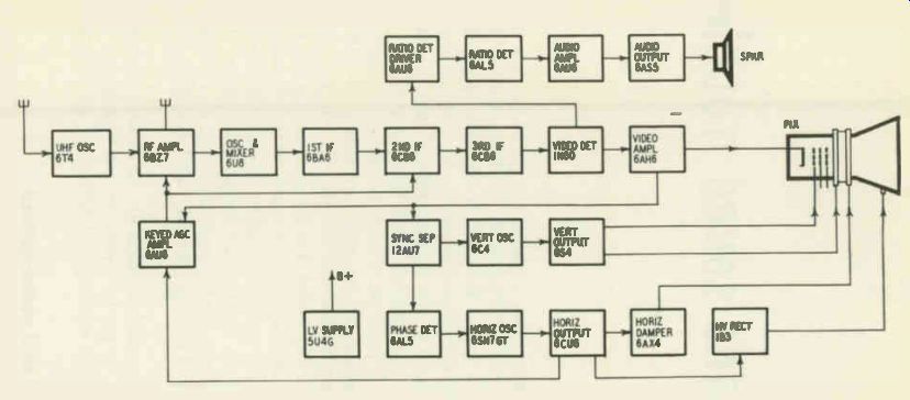
Fig. 401. Block diagram of a typical intercarrier receiver. A brief study
of a receiver's block diagram (when the latter is available) is a valuable
preliminary step to the localization of tube troubles in the receiver.
Pix absent, sound and raster normal
When the picture is absent but sound and raster are normal, the source of trouble usually lies in a stage through which the picture--but not the sound signal-passes (Fig. 401). An important exception to this generalization is this: a defective video detector crystal may kill the picture signal but might permit the sound to get through.
When the picture is missing but sound and raster are normal in an intercarrier receiver, a defective video amplifier is likely if the sound is taken off at the video detector or the first of two video amplifiers. A cathode-to-grid short in the picture tube may also be the cause of the trouble. A defective agc tube may affect the picture much more than the sound, eliminating the first but permitting the second to remain.
Pix and sound absent, raster normal
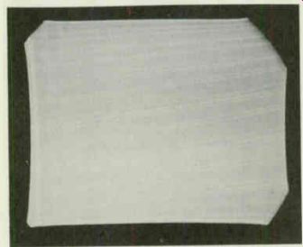
Fig. 402. How raster will look when sync pulses are not reaching the vertical
oscillator. The vertical retrace lines will drift up and down, indicating
that the vertical oscillator is free running or uncontrolled.
When pix and sound are absent at all channel settings but the raster is normal, inspect the raster carefully with the contrast setting advanced. If a noise pattern (speckles, noise dots, etc.) is evident on the screen, trouble in the front end is indicated. Try replacing the front-end tubes one at a time (it is assumed that the possibility of antenna trouble has been eliminated by an in door antenna substitution or some other test). Replace the rf oscillator first if a rushing sound is heard in the speaker--i.e., if the receiver's sensitivity to background noise is high.
If no noise pattern is seen on the screen, examine the vertical retrace lines on the raster. If these diagonal white lines jump up and down and will not remain stationary (Fig. 402), trouble in some stage preceding the sync takeoff point is indicated. Sync pulses are evidently not reaching the vertical oscillator and the retrace lines are unsynchronized.
If, on the other hand, the retrace lines are steady (Fig. 403), vertical sync pulses are generally getting through to the vertical oscillator. (Retrace lines can be steady due to residual hum.) The video signal must, in consequence, be reaching the sync takeoff point and trouble after this point is indicated. When a two-stage video amplifier is present in which the sync pulses are picked off
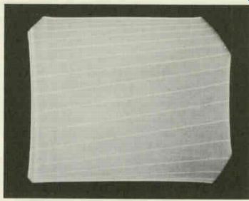
Fig. 403. What the raster will look like when sync pulses reach the vertical
oscillator. The vertical re trace lines will be steady, provided the vertical
hold control has been properly adjusted.
at the plate of the first video amplifier, trouble in the second video amplifier is indicated.
When both picture and sound are absent, it is advisable to inspect the set schematic to determine which stages are common to both picture and sound. In standard intercarrier receivers, pix and sound signals generally ride together as far as the video amplifier, sometimes only as far as the video detector. In at least one case the author knows of, however, the intercarrier sound signal is taken off in a video if stage. So it pays to take nothing for granted and to inspect the schematic.
In older receivers using split-carrier systems, the sound signal is taken off at the mixer or in one of the video if stages (Fig. 404). Substitute tubes (and crystals, if present) in stages common to pix and sound signals to localize the trouble to the unit at fault.
Sometimes a defective sound tube will kill pix as well as sound.
The author has run into more than one split-carrier set where a dead first sound if tube resulted in the detuning of the mixer and caused both pix and sound to disappear.
In sets with stacked tubes a defective audio output tube may be the cause of no pix and sound (Fig. 405) if the video if and other tubes derive their plate voltage primarily through this tube.
In some instances, the raster may be affected by such a defect be cause the supply voltages to the sweep tubes may be changed.
Fig. 404. Block diagram of the older type split-carrier receiver. The sound signal is taken off at the converter.
In some receivers, bias voltage for the agc amplifier is derived from the audio output tube. A defect in this tube may conceivably increase the agc bias and kill pix and sound.
A defective agc tube may cause an excessive bias to be applied to front-end and if stages, killing pix and sound. Replace the tube or tubes present in the agc line to check.
In a circuit such as that shown in Fig. 406, a defective video amplifier may cause an excessive agc bias to be developed, eliminating picture and sound. Since the video amplifier is not common to the sound and video signals in this split-carrier set, the technician would not ordinarily look in the video amplifier for a fault affecting both sound and pix.
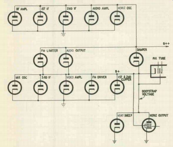
Fig. 405. Block diagram showing a tube-stacking arrangement. Failure of the
audio output tube can decrease the B-plus voltages on the video signal carrying
tubes with which the audio output tube is in series. Picture as well as sound
can be lost.
A loss of emission in the low-voltage rectifier can, in the presence of low line voltage, cause the rf oscillator to stop operating, killing pix and sound without affecting the raster too noticeably.
Intermittent pix and sound
Intermittently disappearing picture and sound are frequently caused by an intermittent tube or loose tube-socket contacts. Gently tap and wiggle the various tubes carrying pix and sound to locate the possible source of such troubles.
Pix and sound reception absent on some channels
When picture and sound are not received on some channels, try changing the oscillator tube. In some receivers, the oscillator circuit design does not provide much margin for aging of components or changes in line voltage. A relatively slight loss in emission in the oscillator tube may consequently cause reception on some channels to disappear. It may be necessary to try several oscillator tubes as substitutes before one is found that will restore satisfactory reception on all channels.
Substitution of the rf amplifier is also suggested when reception on some channels--particularly the high-frequency ones--is not obtained. Replace the first video if amplifier tube as well since a defect in this tube can affect the tuning of the mixer.
Receiver inoperative on uhf
When uhf reception is absent, tune in a station if one is operating in the area. Satisfactory reception of one or more vhf channels points to trouble in the uhf tuner. Substitute tubes and/or crystals in this section to localize the faulty unit.
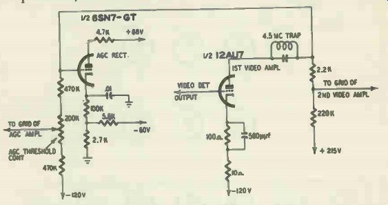
Fig. 406. Video amplifier and associated circuits. Excessive agc bias can
result from a video amplifier defect.
When only one uhf channel is normally received in the area, the possibility of station trouble should not be overlooked. Check uhf reception on another receiver or telephone the station to rule out this possibility.
When no uhf stations are operating in the area and reception on uhf is absent, turn the contrast control to maximum and inspect the raster (it is assumed a normal raster is present). If no snow (noise .signal) is evident, look for trouble in the video if detector or amplifier stages of the receiver. When snow is present, but in small amounts, look for trouble in uhf tuner. (Comparison with the snow present in a normal set that is tuned to an unassigned channel will help the service technician decide what amounts of snow should be expected in the receiver under test.) When the amount of snow noted is normal, trouble in either the vhf or uhf tuner is possible.
When a uhf oscillator tube is replaced, check reception on all uhf channels. Some tubes may perform satisfactorily over only a part of the tuning range.
General troubleshooting
Trouble affecting picture and sound generally calls for tube substitutions in stages common to both signals. When some other stage is the source of the symptoms, the technician may be considerably delayed in his troubleshooting unless he knows what to look for.
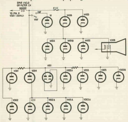
Fig. 407. Block diagram showing tube stacking. V204 is the sound output tube.
Its heavy current will be reduced when it loses emission, causing the plate
voltages on V101, V102A, V203, V305 and V303B to rise. The tubes are shown
as diodes for the sake of simplicity
In receivers using keyed agc circuits, a defective horizontal circuit tube-particularly the horizontal amplifier or damper-can cause the development of an improper agc bias and affect sound, pix and sync. A gassy damper tube, for example, may cause an improperly shaped ac voltage to be fed from the width coil to the plate of the keyed agc tube, causing a varying or otherwise improper agc voltage to be produced, with possible distortion in both picture and sound. The moral is, don't overlook a substitution of horizontal circuit tubes, when symptoms of this kind are encountered in receivers using keyed agc.
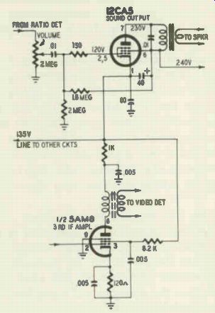
Fig. 408. The audio output and the third if amplifier tubes are in series
and act as a voltage divider. A defect in the sound tube can cause loss of
picture and sound.
Pix missing; sound is strong
When the picture is missing and sound volume is above normal (some experience will generally be needed to determine that a receiver's sound volume is above normal), a defect in an agc tube may be present. In a circuit such as the one shown in Fig. 407, a loss in agc bias will cause an excessive signal input to the video amplifier. The video amplifier may be driven into cutoff, thus killing the picture. The sound signal, on the other hand, will be amplified more than usual because of the loss of agc bias at the rf amplifier and first video if stage in this split-carrier set.
Another example of circuitry in which a defective sound tube may affect both picture and sound is shown in Fig. 408. B-plus voltage to the tuner, video amplifier and agc circuits, as well as the sync separator and clipper, are affected when a fault develops in the audio output tube.
Insufficient signal-contrast inadequate
When insufficient contrast is accompanied by snow in the picture (Fig. 409), try substituting new front-end tubes. If no snow is present, substitute tubes--or crystal--in video signal stages.
Sound may or may not be significantly lowered by a reduction in efficiency of a tube in a stage common to both pix and sound.
Agc tube trouble may be the cause of insufficient contrast-try a new agc tube to check. Agc trouble is particularly likely when a gradual reduction in contrast takes place.
A loss of emission in the low-voltage rectifier may be the cause of reduced receiver sensitivity. In some receivers, separate rectifiers may be used for different levels of B voltage-find and check them all.
6CB6 tubes tend to develop high-resistance leakage between grid and filament (the leakage is generally evident on an ohm meter check, even if the tube is cold). Such leakage in a tube connecting into the agc line will affect the agc bias and reduce the sensitivity of the receiver. Since more than one 6CB6 tube may have developed this trouble, make a resistance check between tube elements before a test replacement of such a tube. In this way, when replacement of a defective tube does not clear up symptoms, it will not be falsely deduced that the original tube was good.
Resetting of the ion magnet may improve contrast when a receiver which has been adjusted for operation in. a strong signal area is used in a location where the signal strength is considerably weaker. The magnet should be set for maximum brightness as usual in a readjustment operation of this kind.
In weak-signal areas, the sensitivity of a receiver may be boosted and contrast improved by various tube substitutions.
When 6AG5's are used in front-end or video if stages, replace them with 6BC5's to increase gain. No wiring changes are necessary in such substitutions (or in the ones listed in the paragraphs that follow).
1 The 6CB6 requires a larger filament current-300 ma-compared to 150 ma for the 6BH6.
Modifying receiver sensitivity
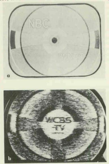
Fig. 409. (a). Weak picture with snow present. (b) Effect of advancing the
contrast control setting with a snowy picture.
A 6CB6 may be substituted for a 6BH6 in the front end to improve sensitivity.' Some 6CB6's are hotter than others--i.e., have a higher transconductance. By testing a substantial number of new 6CB6's from time to time, a stock of peppy tubes can be accumulated and laid aside for use in sets which need the extra push such a tube can supply. Identify these tubes in some way- say, by putting a spot of paint on the base-to avoid mixing them with ordinary 6CB6's in the course of replacement tests.
Some makes of 6CB6-as well as other tubes used in video if and front-end stages-are markedly inferior in performance to competitive brands when used in these stages. To obtain maximum sensitivity from a set, substitute a number of different-make rf and video if tubes and note results. When one brand has been found best, try a number of tubes of that particular make to find the very best. Keep in mind that video if gain can be reduced at least one-half (6 db) by the use of inferior new tubes.
Reduced sensitivity in the presence of weak signals may be due to undesirable characteristics of a 6AL5 used as a video detector.
Some 6AL5's have excessive perveance--that is, they pass a greater current with the same level of applied input signal than other tubes. As a result, the tuned circuit in the detector input is loaded down, its response broadened and its output decreased. To get the best tube for the job, it is sometimes necessary to make tube substitutions while watching the response curve on a scope. Use the tube which gives the highest level of correct response curve. Generally, though, a tube with high perveance is desirable. It will load the coil, but it will also produce more voltage across the diode load resistor.
Changing the low-voltage rectifier present to one capable of producing a higher dc output will also increase receiver sensitivity. A 5Y3-GT, for example, may be replaced by a 5V4-G, fol lowing which the receiver is realigned. Such a change is not recommended unless the technician is definitely sure that components--particularly the input filter capacitor--will not be damaged by the increased voltages resulting from the substitution.
If the rectifier type is not changed, a new rectifier of the same kind may be tried to see whether the signal level cannot be boosted. Such a substitution is particularly recommended when the B voltage is noticeably below normal.
Eliminating snow
The presence of snow in the received picture indicates a poor signal-to-noise ratio. The commonest cause of snow, as far as tubes are concerned, is a defective rf amplifier. The receiver's signal-to-noise ratio is primarily established in the rf stage; a poor rf amplifier, by causing insufficient amplification of the signal, will bring it closer to the tube noise level, thus preventing the effective masking of noise which occurs under normal conditions.
Snow in the picture is inevitable when the incoming signal is too weak to override the rf amplifier's noise level. Snow is, therefore, a characteristic fringe area problem.
Excessive agc bias may be a cause of snow. If the agc setting has been checked, try new agc and video if tubes. A defect in a video if tube may cause excessive agc bias to be applied to the rf amplifier, introducing snow. Sometimes an improperly seated rf amplifier may be the cause. Make sure that this tube is properly inserted and making good contact with the socket.
Noise introduced by various tubes in the receiver's video signal stages may be helping to push the signal-to-noise ratio down. To check on this, make the following test:
1) Place a jumper across the antenna terminals to eliminate the incoming signal. As a further precaution against entrance of a station signal, tune to an unused channel. 2) Turn the contrast control to maximum to amplify tube-caused noise as much as possible. 3) Connect a vtvm across the video detector load resistor.
The voltmeter reading will be solely a noise-caused one. If the voltage measured exceeds 0.6, approximately, the tube noise present is excessive. Tube substitutions should be tried to remedy the condition. Tubes that should be substituted are those in the video detector, front-end and video if amplifier stages.
Corona or arcing in the high-voltage supply may be responsible for an excessive noise reading. It is therefore advisable to disconnect the high-voltage anode connector on the cathode-ray tube and recheck the noise voltage at the video detector (in the test just cited) before making any tube substitutions. Sometimes corona will get worse when the picture tube is disconnected. The high voltage will increase because of the removal of the load.
Weak uhf reception
Low sensitivity on uhf channels is often due to loss of emission in the uhf oscillator tube. If replacement of this tube (as well as other uhf front-end tubes) does not eliminate the symptoms, inspect the contacts of the crystals in this section. Loose or dirty contacts are often causes of poor sensitivity. A thin sealing film at the terminals of a crystal may be impairing its electrical contact, reducing the circuit gain. Clean dirty contacts and tighten loose ones to remedy such troubles.
Crystal replacement should be tried when the possibility of tube and contact trouble has been eliminated. It is generally safest to use an identical replacement for the original crystal. Where a 1N72 is present, however, and snow is seen in the uhf picture, substitution of an 1N82 is likely to improve reception appreciably.
Overloading
Overloading occurs in a stage when the bias of a tube is insufficient or its signal input is excessive. A variety of symptoms may be produced when overloading occurs: dark picture due to excessive contrast, blacking out of the picture, loss of the raster (due to the input signal biasing the picture tube beyond cutoff), sync buzz, as well as loss of horizontal and/or vertical synchronization.
A loss of agc bias is a frequent cause of overloading. A good clue to the trouble is provided by the excessively high detector output that is developed under such conditions. A parallel clue is the low or missing agc voltage that will be read between grid and ground of the agc-controlled tubes. Under normal circumstances, the two sets of voltages are similar in amplitude.
When the set is upended on the bench, the clues cited may be readily investigated; on home service calls, however, the tube substitutions referred to in the paragraphs following (without the voltage tests) will generally prove simpler and faster.
The presence of excessive picture contrast (Fig. 410) is frequently due to agc trouble (loss of agc bias). The existence of such trouble is especially likely when a strong signal produces too much contrast or a blackout ( a black-and-white raster) whereas insufficient contrast, possibly associated with snow, is evident when weak signals are being received.
Fig. 410. Photo of test pattern showing excessive picture contrast. Note
smearing.
If the contrast control requires constant resetting, trouble in the agc clamp circuit may be indicated. Try replacing the diode clamp tube.
A shorted agc tube will sometimes overload the low-voltage rectifier, causing the latter's plates to become visibly red-hot. This symptom, in conjunction with those of overload, will provide a clue to the trouble present.
A gradual increase in contrast, which causes the picture to darken as though the contrast control was slowly being turned to maximum, is often due to a defective agc tube or a gassy video amplifier.
A gassy video if or rf tube or one with cathode-to-heater leakage can cause a reduction or loss of agc voltage. In the case of cathode to-heater leakage, a hum pattern may or may not be visible in the picture. 6CB6 tubes are particularly able to introduce overload due to their tendency to develop high-resistance leakage between grid and filament.
Overloading can be produced by a defective video detector crystal. When the defect causes the crystal's signal output to be reduced, a smaller signal is fed to the agc circuit, causing the receiver gain to go up. When the incoming signal is strong, the excessive gain is likely to result in overloading. A video detector tube whose emission has dropped can be the cause of the same condition for similar reasons.
Fig. 411. Test-pattern photo illustrating white compression due to overloading
in the if amplifier. Note washed out appearance of the picture, poor rendition
of whites.
No snow is present, however. The condition is most likely to be noted on strong signals.
A weak rectifier tube may introduce overloading in receivers using a keyed agc circuit. The plate supply voltage for the horizontal output tube is reduced when the rectifier's emission drops.
The amplitude of the flyback pulse applied to the keyed agc tube is correspondingly lowered, reducing the agc voltage put out by the tube. Agc-controlled stages can be overloaded even though the overall receiver gain may go down due to the decreased B supply voltages.
Clues pointing to the stage in which the faulty tube is located may sometimes be obtained by analysis of the symptoms present.
If washout is observed (a condition in which blacks become gray when the contrast setting is advanced beyond a certain point), the overload is occurring in a stage after the sync takeoff point.
When overload is noted regardless of the setting of contrast and brightness controls in receivers in which a negative voltage supply is used to provide bias voltages, the rectifier in the supply is probably gassy.
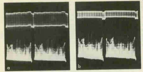
Fig. 412. (a) Normal video detector output waveform. (b) Video detector waveform
when black compression is present. Signals in the gray-black region are compressed,
causing grays to fall into the black region. Sync pulses are also compressed
and reduced in amplitude.
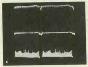
Fig. 412. (c) Video detector output waveform when white compression is present.
Note smaller range of variation at bottom of waveform where the white signals
are, compared to the normal variation in this region shown in Fig. 412-a.
Overload symptoms in which sync buzz is included often point to a defective video amplifier although other tubes may also be responsible.
Overload characterized by white compression (loss of grays in the picture, causing the pix to look flat and washed out) is often due to a faulty rf amplifier (Fig. 411). Defects in either the rf amplifier, agc or video if tubes can be the cause of the trouble.
The presence of white or black compression can be verified by making a scale waveform check at the output of the video detector (Fig. 412).
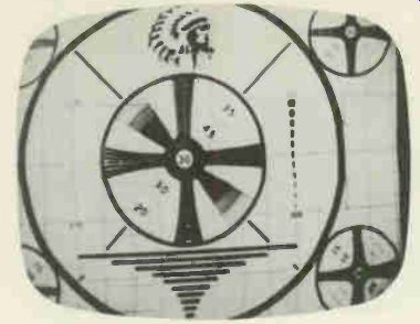
Fig. 413. Test pattern illustrating black compression.
Grays are rendered as black, causing the picture to look dark and excessively contrasty.
Sync and black compression (Fig. 413) frequently indicates overload in the video if stages due to insufficient agc bias. Such compression may readily be detected by advancing the brightness control and adjusting the vertical hold control until the picture hovers with the horizontal blanking bar positioned somewhere around the middle of the tube. If the sync pulse hammer is not much darker than the blanking bar proper, sync and black compression is indicated (Fig. 414). The picture will be dark and excessively contrasty when this kind of trouble is present; sync will tend to be lost if the condition is severe.
When the signals being received are excessive (a problem in high-signal areas), overloading is a normal result. One of the ways in which the condition can be remedied is the proper selection and substitution of video if tubes. Tubes with lower than average gain should be found and used. Proper selection of tubes-sometimes merely the interchanging in their sockets of the video if tubes present-may greatly reduce overload symptoms by increasing the signal-handling ability of the receiver.
It is particularly important that the first if tube have a trans conductance that is average rather than above average. Use of tubes with transconductance that are well below average is not recommended. A weak if tube in an uncontrolled stage can result in low detector output. This means a lowered agc voltage and can produce an overloaded first if stage.
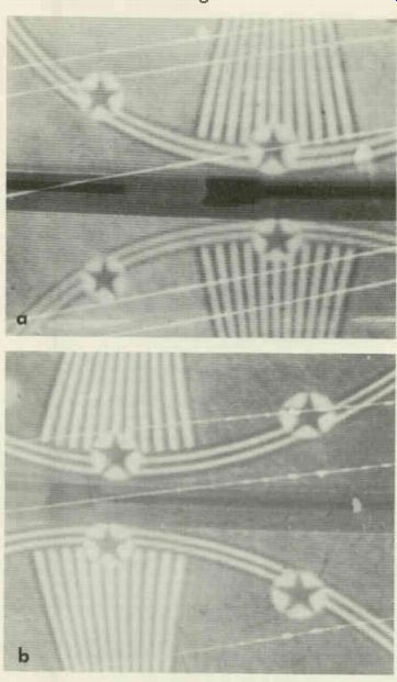
Fig. 414. The photo at the top shows the normal appearance of vertical blanking
bar. Note that the sync hammer is black, while the blanking bar proper is
gray. The lower photo illustrates the effect of sync compression on the sync
pulse and blanking bar. The reduction in sync pulse amplitude causes the height
of the sync pulse to fall closer to the blanking signal level. As a result
the shading of both becomes similar.
When overload occurs only at intervals and it has been definitely ascertained that the agc voltage is reduced or lost at such times, check for a dc voltage drop across the grid-return resistors of the video if and rf amplifier tubes to localize the trouble further.
Normally this voltage should be zero; if it isn't, grid current is probably flowing in the tube with which the resistor is associated, possibly because of the development of gas in the tube. Open the coupling to the grid resistor from the preceding stage; if the voltage drop across it remains, a gassy tube is definitely indicated.
Negative picture The technician not infrequently encounters a set in which negative pictures are received-one in which normally black areas are white and normally white areas are black (Fig. 415). Overloading is frequently the cause of such phase reversals, particularly when vertical and/or horizontal synchronization is continuously or intermittently affected. An excessive signal in the video if tube grid circuit can produce a negative picture.
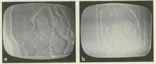
Fig. 415. (a) Negative picture caused by overloading. An inoperative agc
tube can cause such overloading by removing the bias from agc-controlled stages.
Erratic horizontal and vertical synchronization are often associated with
the negative picture. (b) Another example of a negative picture caused by
agc trouble. In this case, synchronization has not been impaired. The symptoms
illustrated were seen when a medium-strength signal was coming in. With a
weak signal and the contrast control setting advanced, the picture may look
normal in some cases.
Fig. 415. (c) Negative picture caused by low emission in a 5U4-G rectifier.
The 5U4-G in question provided high B plus for the horizontal amplifier tube.
Reduction of the rectifier tube's output resulted in the feeding of a smaller
pulse from the horizontal amplifier to the plate of the keyed agc tube, decreasing
the agc voltage and causing overloading of the agc-controlled stages.
A defective video amplifier can be the cause of a negative picture. Leakage of video signal past the inoperative amplifier takes place in such a case. The phase of the signal at the picture-tube input is opposite to what it should be since one stage of phase in version has been omitted. A negative picture results.
A defective crystal used as a video detector may be the source of a negative picture. So can a normal crystal that has been improperly connected and as a result is producing an output signal of the wrong polarity.
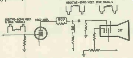
Fig. 416. The sync pulses should be negative-going on a scope waveform test
when the video amplifier output signal goes to the grid of the cathode-ray
tube. It is assumed that the scope does not invert the signal. When the video
amplifier feeds to the cathode of the picture tube, the sync pulses should
be positive-going.
Trouble in a picture tube itself can produce a negative picture.
Before making a laborious substitution to test for such a source of trouble, simply check the scope waveform at the point where the video signal is fed to the tube. If the signal is applied to the grid, the polarity of the sync pulses should be negative; they should be positive if the video is fed to the cathode (Fig. 416). If the. signal polarity is correct but a negative picture is obtained anyway, trouble in the C-R tube is indicated and another tube should be substituted. (It is assumed that voltage and resistance tests between picture-tube elements and ground have eliminated the possibility of circuit trouble.) Loss of emission in a low-voltage rectifier, in the type of circuit shown in Fig. 417, may result in negative picture. Knowing what to look for in such instances can save the technician considerable troubleshooting time.
Poor definition-improper focus
A blurring of the entire picture is generally produced by improper focus. The vertical and horizontal wedges in the test pat tern will not be sharply defined when this condition is present (Fig. 418) and neither will the scanning lines of the raster. (Reduce the contrast setting to zero, eliminating the picture, to examine these lines.) When adjustment of the focus control and/or focus magnet proves ineffective in clearing up the condition, one of the following troubles may be present:
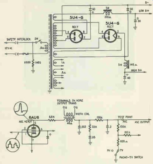
Fig. 417. Typical power supply and agc picture circuits. The 5U4-G at the
right (upper drawing) provides high B plus for the horizontal output tube
which feeds pulses to the plate of the keyed agc tube (lower drawing). A defect
in this rectifier tube can affect age operation without producing visible
symptoms of malfunctioning in other circuits.
Loss of emission in a low-voltage rectifier. The focus control may approach (but not reach) proper focus at one end of its range, when such a trouble exists.
A defective high-current tube-such as a video or power amplifier-may be reducing the current flow through the focus coil (when one is present) to a point where proper compensation by focus-control resetting is not possible.
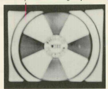
Fig. 418. Effect of improper focus on the test pattern.

Fig. 419. Focus tube and associated circuit used with picture tubes employing
high-voltage electro static focus.
In some receivers, the power amplifier tube is in series with the focus coil. A weak or gassy tube in this stage will severely affect the focus. Try replacing the tube before going on to circuit tests.
In electrostatically focused sets using a separate tube (usually a 1 1/2) to provide the focus voltage needed, reduced emission or some other defect in this tube may make it impossible to achieve proper picture focusing (Fig. 419). The same is true of magnetically focused sets that use a separate focus control tube. (Fig. 420). Improper focus may be due to a gassy cathode-ray tube. A test with a tube tester or substitution of a new picture tube will verify whether the trouble lies here.
Poor focus can be due to magnetization of the picture-tube gun. If substitution of an identical tube restores proper focus, a defect of this type is possibly present. Try demagnetizing the picture tube (as described in the section on C-R tubes) before permanently replacing it with a new one.
Reduced emission in the horizontal output tube may have an effect on focusing since the magnetic fields of the yoke and focus coils interact to some extent. The loss in emission may impair focus even when it has no apparent effect on picture width or brightness. The defocusing can also be due to a drop in high voltage. Substitute a new horizontal output tube to test for as well as remedy this kind of defect.
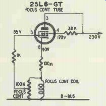
Fig. 420. Focus control tube and associated circuit used in some receivers.
In those electrostatically focused sets in which an adjustable focus voltage is provided, rotating the cathode-ray tube 180° will remedy some cases of poor focus.
Improper setting of ion, centering or other magnets present on the neck of the C-R tube may be responsible for impaired focus and should be investigated when no likelier sources of trouble can be found.
A condition similar to a slight impairment of focus may be noted (Fig. 421) when the size of the scanning spot has increased for some reason. Possible causes for such an increase include: improper positioning of the ion magnet; gassy C-R tube; loss of emission in a tube in the horizontal or high-voltage section (leading to a reduction in the high voltage) and, of course, an improper focus-control setting.
To check the spot size, observe the white scanning lines in the picture or test pattern. In Fig. 421-a illustrating a normal condition, the scanning lines are narrow and the black horizontal spaces between them are clearly visible. In Fig. 421-b illustrating the effect of an enlarged spot, the increase in the width of the scanning lines has caused the dark in-between spaces to become narrower, poorly defined and almost invisible.
Fig. 421. (a) Appearance of section of test pattern when scanning-spot size
is correct. Appearance of same portion of test pattern (b) when scanning-spot
size is larger than normal. Note that the dark spaces between scanning lines
are no longer clearly visible.
Resolution troubles
Resolution is a measure of picture definition. Good resolution requires the uniform amplification of all the frequencies in the receiver's video bandpass. When high video frequencies are not adequately amplified, picture detail will not be reproduced satisfactorily. The loss of resolution in such a case can be most readily detected by inspecting a test pattern. The test pattern's vertical wedges will not be clearly defined all the way to the center of the pattern as they should be ideally. If no test pattern is being trans mitted, check the reproduction of small light areas in the picture.
When resolution is poor, the fine-tuning control is correctly set and no slight ghost effect (due to a mismatch in the antenna system) is evident, try replacing the video detector or video amplifier tube. (When a crystal is used as the video detector, replace it only when likelier sources of trouble have been eliminated.) A bad video if amplifier, or even a defective picture tube, may also be the cause of poor resolution.
Picture smear
Fig. 422. Effect of smearing on the test pattern. Symptoms vary somewhat
from case to case.
When response is impaired at low frequencies, smearing may be introduced into the picture. Smearing most noticeably affects large objects (Fig. 422). White or black edges in the picture, instead of being sharply defined, are smeared generally in the direction of the right side of the screen. Trailing shades ranging from black to white may be seen after large black objects; these shadings go from white to black after large white objects. The picture as a whole will look fuzzy. Smearing is usually due to poor reproduction of low video frequencies.
If the fine-tuning control is found to be correctly set and the presence of smearing on several channels has ruled out the possibility of station trouble, try replacing the video amplifier tube first, then the video detector. A defective video detector crystal may load down the tuned circuit with which it is in series, causing smear via misalignment.
When a loss in fine detail is associated with the smear, check the setting of the ion magnet. In many sets, a slight mis-setting of the ion magnet can impair focus and produce a condition resembling smear. Defects in the video if amplifier and C-R tubes may also be the cause of picture smear.
A source of picture smearing likely to be overlooked is the too close coupling of a horizontal yoke lead to the picture-tube cathode or grid lead. Improper lead dress of this kind can cause horizontal sweep signals to be developed between grid and cathode of the tube, causing grid current to flow in the C-R tube on steep signal peaks. Smearing may result due to the changed picture tube bias. Redress the leads to test for as well as correct the trouble.
Miscellaneous picture troubles-engraved effect
When the picture resembles an engraving and the settings of the fine-tuning and contrast controls are correct, substitute new tubes for the video amplifier and video detector to check whether a defect in these tubes is responsible for the symptoms.
Ghosts due to bad tubes It is not too well known that a defective tube may cause ghosts or multiple images (Fig. 423) to be seen in the picture. The condition may be explained as follows: Rf signals get into the receiver via pickup in the antenna system, which is desired, and also by direct pickup in the rf input circuits, which is undesired. Under normal circumstances, the signals picked up at the rf input are much weaker than the desired ones entering by way of the antenna system and the gain of the receiver is not great enough to make them visible.
When a defective rf amplifier tube is present, however, the direct-pickup signal may be as strong, or possibly even stronger, than the one coming in from the antenna. Furthermore, the gain of the receiver goes up considerably because the reduction in signal produced by the rf amplifier defect lowers the agc voltage. Both the direct-pickup and antenna signals may thus become visible.
Since the tuner pickup is not directional, signals from the same station that come in via different paths and have been delayed in varying amounts by reflection from different surfaces may be simultaneously accepted, and as a result, multiple images will be seen.
Clues pointing to the possible existence of such trouble are: If the ghosts present shift in position or the quality of the picture changes when people move around in the vicinity of the receiver, abnormally strong direct pickup via the tuner is indicated.
(This statement applies to receivers that are connected to an out door antenna.) If the picture's ghost content remains unchanged with the antenna disconnected from the receiver input, the same condition is indicated.
Fig. 423. Ghosts in test pattern.
Replace the rf amplifier to determine if a fault in this tube is producing the symptoms. The agc tube may next be replaced if rf amplifier substitution causes no change in symptoms. (A defective agc tube may increase the sensitivity of the receiver to a point where direct-signal pickup becomes evident on the screen.) Sound troubles-hum in sound; pix and raster normal A distinction should be made between 60-cycle hum and buzz, which sound somewhat similar. Such a differentiation will pro mote a faster localization of the source of trouble. Hum is a smoother, less harsh sound than sync or vertical sweep-signal buzz and may be readily identified because of this characteristic.
Improper setting of the fine-tuning control will cause hum to be heard in many receivers. Check for this condition before going on to other tests.
When hum is heard with the volume control setting at zero, try replacing the tubes in the audio amplifier section and note results.
When reduction of the volume control setting to zero eliminates hum, cathode-to-heater leakage in a sound if or sound detector tube may be present. Such leakage in a sound if tube will generally result in hum being heard only when a station is coming in, a characteristic that should aid in the rapid identification of the source of trouble.
In certain receivers a hum may appear in the sound that varies with the setting of the brightness or contrast controls. Stray coup ling between video circuits and the sound if amplifiers is probably the cause. Replacement of the sound if tubes or the use of tube shields over them should clear up the trouble.
A source of hum that may be overlooked is cathode-to-heater leakage in a tuning-indicator tube.
Buzz in sound
Buzz in intercarrier sets falls into one of two basic categories: I) sync buzz and 2) pickup of the vertical sweep signal by an audio circuit. To determine which kind is present, remove the vertical oscillator. If the buzz stops, condition 2 exists. In many cases, presence of the condition may be verified simply by rotating the vertical hold control. If the buzz changes in pitch, it is due to vertical sweep-signal pickup. Such pickup is generally caused by improper dress of a vertical circuit lead--i.e., too close positioning of the lead to an audio tube.
When the buzz present is not eliminated by the removal of the vertical oscillator tube, an overloaded video if or amplifier tube may be present. Overloading in a video if tube can cause buzz for the following reason: The portion of the video if signal most likely to cause overloading is the part that is modulated by the sync pulse. This is so be cause the sync-pulse level of the signal is the peak or maximum level. When the if signal is so large or the bias of the video if tube so low that overloading takes place, the tube affected is driven to cutoff at the sync-pulse rate, 60 and 15,750 cycles per second. Interruption of the sound signal at these rates occurs in consequence.
The picture is not affected because the interruptions occur during blanking time. The sound is, however, very seriously affected by the 60 -Hz interruption (the 15,750-cycle interruption is not like ly to be audible); the holes that are regularly punched in it are heard as a buzz.
When the video amplifier is overdriven, the 4.5 -MHz sound signal present in this stage is interrupted at sync-pulse rates, causing the same symptoms. This applies only to sets where the sound is taken off at the video amplifier.
An overloaded video if amplifier is, perhaps, most often due to a video if tube which is either gassy or has cathode-to-heater or grid-to-filament leakage. Replace the tubes in this section to test for such a source of trouble. A preliminary measurement of agc and other bias voltages, where this may be readily done, will verify whether insufficient bias is present and warrants the tube-replacement tests just referred to.
A gassy or otherwise defective video amplifier may be responsible for introducing buzz. A defective germanium crystal used as a video detector may also be the source of buzz (poor contrast and sync instability may or may not be associated with it). Substitution is the best way to check a crystal.
An unexpected source of buzz may be linked to a defective picture tube. When the C-R tube is weak, the set owner may advance the contrast control to a higher setting in an effort to get a more satisfactory picture. When the setting of the control is such that the video amplifier bias is close to cutoff on signal peaks, a change in scene that pushes the signal peaks beyond cutoff will produce sync buzz.
Still another cause of buzz is improper lead dress. If the cathode or grid lead of the picture tube is positioned too close to a first audio tube, sync pulses present on this lead may be coupled to the audio tube, producing buzz in the sound. Avoid changing the dress of picture-tube leads during tube substitutions to prevent introduction of such trouble.
In some instances, pickup of the kind just described may take place because of a missing shield on a first audio tube. Add a shield when this condition is suspected and note results. If a shield is al ready present, make sure it is properly grounded.
Proper shielding of a first audio tube is particularly essential when a picture tube with no outer Aquadag coating is used in the set. A coating of this type acts as a shield; in its absence, radiation of buzz-creating signal becomes much greater. (A more complete description of Aquadag is given in Section 7.) A chalky substance may,. form on the outer Aquadag of some picture tubes and prevent proper contact of the Aquadag to the spring that grounds it to chassis. Buzz may result since the shielding is no longer adequate. Wash off the chalky material with a damp cloth and dry the area affected very thoroughly. Gently touching up the area at which the spring makes contact with a soft, rather blunt lead pencil will complete the repair.
The procedure just described should not be used on all makes of picture tube unless the service technician is sure that the Aqua dag is not water-soluble. In many cases it is and can be washed away when water is applied.
In all sets, buzz may be introduced when the grounding spring that contacts the Aquadag is bent, missing or does not touch the tube.
Buzz that is not affected by the volume control may be due to corona. Reduced picture brightness or other symptoms of corona are likely to be associated with the buzz in this case.
A defective sound if amplifier or detector tube may be responsible for buzz. Replace the tubes in these sections as a test. Buzz is also caused by a misaligned sound detector transformer.
In some receivers operating in strong-signal areas, use of certain 6AG5 type tubes in agc-controlled first video if stages can intro duce buzz. Some of these tubes have a grid cutoff characteristic which is exceptionally sharp; a tendency to premature cutoff in the presence of large agc voltages produced by strong signals there fore exists. A tube of this type need not be discarded; it can be used in some video if stage where fixed bias is applied and over loading is therefore less likely.
Other sound troubles--sound absent, pix normal
When a normal picture is received but sound is missing and no background noise is audible, look for a defective tube in the sound section. Click tests can be used to locate the defective section.
These tests consist of removing the audio tubes one at a time, starting with the power amplifier and proceeding backward. Listen for a clicking sound as each tube is removed. The clicks should become slightly louder the farther away you go from the last tube since more stages of amplification are being added. When a stage is reached where withdrawal of the tube produces no click or too faint a click, the tube in question should be replaced and results noted. (This test should not be tried in sets with series-string filaments.) If sound is missing and a background hiss is audible (in a split carrier set), the rf oscillator may be to blame. Slight retouching of the oscillator tuning adjustment will often restore circuit operation to normal; try a new oscillator tube if it won't.
Weak and/or distorted sound
When the sound is weak and/or distorted but the picture is normal, substitute tubes in the sound section to locate the defective one (it is assumed that the adjustment of the fine-tuning control is correct). In receivers using stacked-tube circuits, a weak video if or sync tube may be responsible for poor sound. The picture will, however, generally be impaired as well in such instances.
In series-filament receivers using power amplifiers with high voltage filaments, a creeping distortion in the sound that appears after the set has warmed up and grows progressively worse is usually due to a defective audio power amplifier tube.
In some cases of weak sound, the trouble is caused by excessive current drain in the low-voltage power supply produced by a gassy or grid-emitting tube. (The drop in B voltage may not be large enough to affect the picture noticeably.) Remove the tubes one at a time and note whether the B plus (which should be monitored with a dc voltmeter) jumps up very appreciably at any time.
The B voltage will, of course, increase markedly when a high current tube (such as the video amplifier or audio power amplifier) is withdrawn. The increase in voltage when a low-current tube is removed should, however, be very slight. If an excessive B-voltage increase is noted when any tube is withdrawn, substitute another tube and note results.
In one case known to the author, a gassy picture tube loaded down the power supply heavily enough to weaken the sound greatly but left the picture relatively unaffected.
Noisy sound
When the sound is noisy, a sound if limiter or detector tube may be defective. Replace these in turn and note results. When the sound is weak as well as noisy, a weak sound if tube is the likeliest possibility.
Noise drowns out desired sound
A motorboating sound which occurs when the receiver is first turned on is generally caused by a defective oscillator-mixer tube.
Low emission in one or both sections of the tube can cause the trouble. The motorboating sound rises in pitch as the receiver keeps warming up and finally disappears.
Another mixer-oscillator defect may cause a high-pitched whine to become audible when the receiver begins to operate. The picture may break up during this interval. After a short time, the symptoms disappear. Large variations in interelectrode capacitance in the oscillator are generally responsible for the condition.
Sound and picture do not track
When best sound does not appear at the setting where the picture tuning is correct, one of several tube troubles may be present.
The rf oscillator or amplifier tube may be defective. Or oscillation in the video if stages, promoted by a tube defect in this section, may be producing the symptoms. Trouble in the rf oscillator is particularly likely if drift is creating the symptoms.
Where an afc circuit is used to control the rf oscillator, an in effective fine-tuning control points to trouble in the afc discriminator. (The output of the discriminator is used to control the frequency of the rf oscillator.)